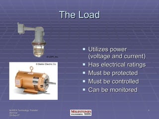
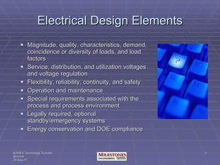
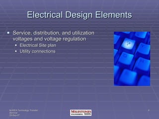
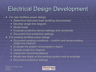
The document discusses key elements that a project engineer needs to know when designing an electrical system, including the load, power source, protection, monitoring and control. It outlines factors to consider such as load ratings and locations, voltage regulations, protective device settings, and system documentation. Design development involves determining the total load, developing single line diagrams, evaluating the existing system, and implementing recommendations while ensuring safety codes and standards are followed.
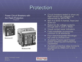
Dear All,
Here i glad to introduced with a basics of Design Electrical which is helpfull to understand the concept of electrical.
I hope you like these concept & prefered the same.
Thanks& Regards,
Pankaj V. Chavan
( 95615 73214 )
Dear All,
Here i glad to introduced with a basics of Design Electrical which is helpfull to understand the concept of electrical.
I hope you like these concept & prefered the same.
Thanks& Regards,
Pankaj V. Chavan
( 95615 73214 )
This presentation is from my talk Delivered to Young Engineers to have a brief overview of :
1. Substation And Its Types
2. Substation Equipment
3. Substation Grounding
4. Design Consideration
5. Bus Switching Scheme
6. Basic Insulation Level and Its importance
7. Fault level and its importance
8. Other Equipment
9. Substation IEC 61850 Protocol Basic
It will be helpful for Engineering students to have an overview from a Practical point of view. Widely publicize it for benefit of others.
This Presentation is about l.v switch gear design, presented during the graduation project final discussion 15/7/2018.
It presented a good summary of switch gear components and types and practicing on AL.HAMOOL W.T.P M.D.B design using SIEMENS SIVACON S8
A brief about 33kv Substation........
like and share.................
want some help in your ppt or in any project visit..
https://www.fiverr.com/dawachya
In-Country Training
On
Operation, Maintenance, Protection & Control of 33/11 kV Substation
Project Name: Design, Supply, Installation, Testing & Commissioning of 33/11 kV sub-stations with source end feeder bays.
Contract No: BREB/UREDS/W-01A-001/02/2016-2017
BREB/UREDS/W-01A-002/03/2016-2017
BREB/UREDS/W-01A-004/04/2016-2017
The solar energy is converted to electrical energy by photo-voltaic cells. This energy is stored in batteries during day time for utilizing the same during night time. A charge controller, or charge regulator is basically a voltage and/or current regulator to keep batteries from overcharging. It regulates the voltage and current coming from the solar panels going to the battery.
ATENÇÃO LIDERANÇAS<<<
Link liberado para pré cadastro:
FAÇA JÁ SEU CADASTRO E SEJA PIONEIRO NESSE NEGÓCIO ESPETACULAR!!!!!!!
http://clubedelideres.net/?afiliado=fotografia
VEJAM AS VANTAGENS DE FAZER PARTE DO CDL
CLUBE DE LIDERES: Você obterá por só R$ 25,00.
• Sistema de Gerenciamento de Rede com direito de revenda e 100% de lucro!
• Ganhos rápidos de ciclos na matriz 2x2 (mesmo só com derramamentos)
• Residual mensal na matriz global 2x10 – meta da primeira fase R$ 6.963,00
• Premiações na matriz 2x7 conforme for atingindo os níveis sendo eles:
1º nível: página de captura
2º nível: auto responder
3º nível: site personalizado
4º nível: adesão na primeira empresa de mmn
5º nível: adesão na segunda empresa de mmn
6º nível: adesão na terceira empresa de mmn
7º nível: adesão na quarta empresa de mmn
• E muito mais novidades chegando por ai!
assista ao vídeo https://www.youtube.com/watch?v=ShXwyFNikVE
Seja um vencedor!
FAÇA JÁ SEU CADASTRO E ATIVE SUA CONTA
http://clubedelideres.net/?afiliado=fotografia
jrfotografia.desner@outlook.com
VAMOS QUE VAMOS PARA O SUCESSO!!!
EV Charging Infrastructure: Littelfuse Solutions to Enhance Safety, Efficienc...Littelfuse
Discover the wide range of Littelfuse EV charging infrastructure solutions in our automotive electronics portfolio, including silicon carbide (SiC) devices.
Littelfuse Solutions: Industrial Motor Drives and Soft StartersLittelfuse
Learn how Littelfuse products provide protection and power control for variable frequency drives and soft starters to improve motor life and energy efficiency.
Learn how fuses work, how Littelfuse fuses can help industrial facilities comply with NEC 240.2 and NEC 240.4, and how to select the right fuse for your application.
Littelfuse offers component solutions for wireless chargers, power adapters, charging cables, charging pads, and transmitters for consumer, medical, and industrial applications.
12. Nominal System Voltages Substation 13.2kV; 69kV; 115kV Plant Distribution 4160V; 480V; 208V Control 120V Signal 24V
13.
14. Working Clearances under 600V 2005 NEC Article 110.26 Spaces About Electrical Equipment (C) Entrance to Working Space. (2) Large Equipment. For equipment rated 1,200A or more, an entrance measuring not less than 24 in. wide and 61/2 ft high, is required at each end of the working space. Where the entrance to the working space has a door, the door must open out and be equipped with panic hardware or other devices that open under simple pressure. This material was extracted from Mike Holt Training Materials copyright 2007 by permission. Visit www.NECCode.com or call 1.888.NEC.Code (632-2633) for more information. NEC ® 2002
Design elements Load types and characteristics [Mike C and 2H] Power sources – utility and private [Mike C and 2H] Discussion on protective devices and safety aspects [HRZ] Devices for monitoring and control and system discussion [Mike P] Pulling it together SLD power connection diagram P&ID control and monitoring diagram
Load: If it needs electricity to operate: rotate, revolve, move, heat or illuminate, it’s a load. Is a switch a load? Motors [process and building] Lights control cabinets contain a system of loads: PLCs, indicating lights, relays Characteristics and ratings: Single phase, three phase, frequency, [unit of power is KW or KVA] Voltage, amperage Enclosure types for different operational and environmental factors: Safety: Protective devices for transient voltages, voltage surges, overcurrent, overvoltage, and ground fault Enclosures for energized parts, raceways, insulators Control: On, off, and somewhere in between [vary voltage or current to control rotation or intensity] Monitor: Power: Always metered by the utility but instrumentation is used for individual monitoring of equipment or systems to determine efficiency Run time: to schedule maintenance Temperature: to determine potential problems
These elements are considered in all designs, though all may not be applicable. Without exception, project engineers need to know about the LOAD, the SOURCE, and the CONTROL, to ensure SAFETY, COMPLIANCE and provide for proper MAINTENANCE The LOAD can be building or 1,000; but each load receives the same thought process and evaluation to follow recommended practices, standards and codes. It’s all about protection of life and property.
After all the loads are tabulated [hp converted to kva], the service or the power source size is determined. 2. Source 2.a. What is the source? 2.a.1. Utility transfomer 2.a.2. Distribution transformer 2.a.3. Generator 2.a.4. UPS or battery 2.b. What are the source ratings? 2.b.1. KVA- transformer 2.b.2. Volts (primary & secondary on transformer) 2.b.3. Kw (generator) 2.b.4. Phases 2.c. How is the source protected? 2.c.1. Circuit breaker 2.c.2. Fuse 2.d. Where is source protection located? 2.d.1. Panelboard 2.d.2. Enclosure 2.e. Where is the source located? 2.e.1. Pole 2.e.2. Padmounted 2.e.3. Room (elevation, number)
The newsroom at WBRZ-TV, the ABC television affiliate, in Baton Rouge, LA, is another flywheel application. The news operation is active 24 hours every day of the year. Television and radio stations are required by law to continue broadcasting if power is lost in the power grid.
IEEE Standard for Industrial and Commercial Power Systems Low: 120/240 to 600V – used to supply utilization equipment Medium: 2400 to 69kV – supply distribution transformers or large motors [13.8kV and lower] High: 115 to 230kV – transmission voltage between substations IEEE Power Engineering Society High = above 1000V NEC High = over 600V
Article 110 requires specific clearances around equipment based on voltage levels, and changes have occurred from the 2002 NEC. Ea
Article 110 requires specific clearances around equipment based on voltage levels, and changes have occurred from the 2002 NEC. The requirement that equipment rated 1,200A or more had to be over 6 ft wide before an entrance was required at each end of the working space was removed. The argument for the change was that the size of the arc blast is directly related to the ampere rating of the equipment, and not the physical width of the equipment.
Based on the information provided and discussions that ensue, the early design decisions are made. Article 110 requires specific clearances around equipment based on voltage levels.
What are the options to protect the load? 3.a. How is the load protected? 3.a.1. Circuit breaker 3.a.2. Fuse 3.b. Where is protection located? Environment? 3.b.1. Panel 3.b.2. MCC These devices are assembled and connected to conductive metal called bus bars. the energized parts are protected inside panels which will have NEMA enclosure ratings, which Mike Currie will address later.
E-rated fuses: Bolt-In • EBI055 - E-rated medium voltage, current-limiting fuses for transformer and feeder protection. CL-14 • ECL055 - E-rated medium voltage, current-limiting fuses for transformer and feeder protection. • ECL155 - E-rated medium voltage, current-limiting fuses for transformer and feeder protection. for potential & small power transformers • JCD - Indicating and non-indicating E-rated medium voltage, current-limiting fuses for potential & small power transformers. • JCE - Indicating and non-indicating E-rated medium voltage, current-limiting fuses for potential & small power transformers. • JCI - Indicating and non-indicating E-rated medium voltage, current-limiting fuses for potential & small power transformers. • JCQ - Indicating and non-indicating E-rated medium voltage, current-limiting fuses for potential & small power transformers. • JCT - Indicating and non-indicating E-rated medium voltage, current-limiting fuses for potential & small power transformers. • JCW - Indicating and non-indicating E-rated medium voltage, current-limiting fuses for potential & small power transformers. for transformer & feeder protection • JCU - Indoor/enclosure E-rated medium voltage, current-limiting fuses for potential & small power transformers with blown fuse indication. • JCX - Indoor/enclosure E-rated medium voltage, current-limiting fuses for potential & small power transformers with blown fuse indication. • JCY - Indoor/enclosure E-rated medium voltage, current-limiting fuses for potential & small power transformers with blown fuse indication. • JCZ - Indoor/enclosure E-rated medium voltage, current-limiting fuses for potential & small power transformers with blown fuse indication. • JDZ - Indoor/enclosure E-rated medium voltage, current-limiting fuses for potential & small power transformers with blown fuse indication. for transformers and feeders • MV055 - E-rated medium, voltage current-limiting fuses: for transformer and feeder protection. • MV155 - E-rated medium, voltage current-limiting fuses: for transformer and feeder protection. Fast-acting fuses Non-time delay • HVA - Medium voltage, non-time delay, fast-acting fuses. • HVB - Medium voltage, non-time delay, fast-acting fuses. • HVJ - Medium voltage, non-time delay, fast-acting fuses. • HVL - Medium voltage, non-time delay, fast-acting fuses. • HVR - Medium voltage, non-time delay, fast-acting fuses. • HVT - Medium voltage, non-time delay, fast-acting fuses. • HVU - Medium voltage, non-time delay, fast-acting fuses. • HVX - Medium voltage, non-time delay, fast-acting fuses. R-rated fuses for motor circuit protection • JCG - Indoor/enclosure R-rated medium voltage, current-limiting fuses for motor circuit protection. • JCH - Indoor/enclosure R-rated medium voltage, current-limiting fuses for motor circuit protection. • JCK - Indoor/enclosure R-rated medium voltage, current-limiting fuses for motor circuit protection. • JCK-A - Indoor/enclosure R-rated medium voltage, current-limiting fuses for motor circuit protection. • JCK-B - Indoor/enclosure R-rated medium voltage, current-limiting fuses for motor circuit protection. • JCL-A - Indoor/enclosure R-rated medium voltage, current-limiting fuses for motor circuit protection. • JCL-B - Indoor/enclosure R-rated medium voltage, current-limiting fuses for motor circuit protection. • JCR-A - Indoor/enclosure R-rated medium voltage, current-limiting fuses for motor circuit protection. • JCR-B - Indoor/enclosure R-rated medium voltage, current-limiting fuses for motor circuit protection. Type H & N (High Surge) • EEI-NEMA - Medium voltage fuses: Type H (high surge) Type K (Fast) • EEI-NEMA - EEI-NEMA Type K (fast-acting) Type T (Slow) • EEI-NEMA - EEI-NEMA Type T (slow-acting).
What are the options to control the load? What parameters should be monitored? Individual component devices are useful but only if they work in concert. Field devices must report to a command center where decisions are made and action taken. Someone watches a gauge or gauges and turns a knob or flips a switch based on the information displayed or the decision to open a value, turn on a pump, or raise a temperature is determined a multitude of feedback set points that are processed in nanoseconds. SCADA systems can monitor and control plant and process equipment to save clients time and money Verify system performance for regulatory compliance, energy cost savings, Anticipate schedule maintenance times – reduce unanticipated down times Equipment Temperature switches Ammeters, Voltmeters, KWh meters Phase monitors Under/overvoltage monitors Process Level transmitters/ switches Pressure switches Motorized valves
Individual component devices are useful but only if they work in concert. Field devices must report to a command center where decisions are made and action taken. Someone watches a guage or gauges and turns a knob or flips a switch based on the information displayed or the decision to open a value, turn on a pump, or raise a temperature is determined a multitude of feedback set points that are processed in nanoseconds. SCADA systems can monitor and control plant and process equipment to save clients time and money Verify system performance for regulatory compliance, energy cost savings, Anticipate schedule maintenance times – reduce unanticipated down times Monitoring devices: Equipment Temperature switches Ammeters, Voltmeters, KWh meters Phase monitors Under/overvoltage monitors Process Level transmitters/ switches Pressure switches Motorized valves
All these devices are tied together to form our operational systems. we represent these systems in power diagrams and P&IDs process and instrumentation diagrams, which will be discussed in greater detail later in the presentation.
Early discussion of the design is beneficial To minimize change orders during construction Planning for future growth Safe, long term operation
Load lists provided by the PM are used to develop single line diagrams and P&ID’s