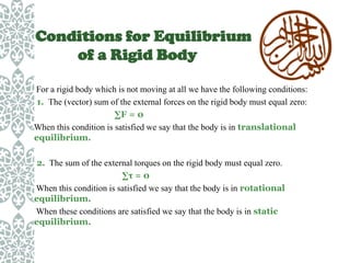
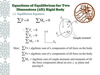
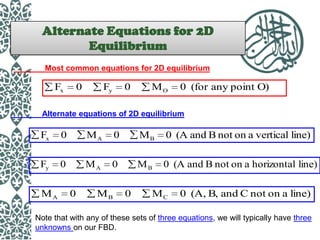
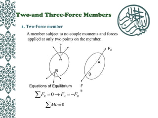
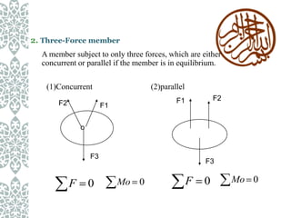
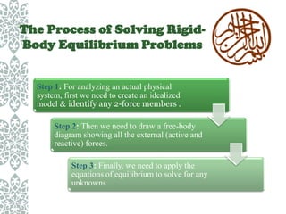
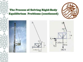
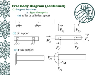
CE – 416
Pre-stress Concrete Design Sessional
Presented by
Fariya Rahman Moho

Student No. : 10.01.03.014
Course Teachers
Munshi Galib Muktadir
Ms Sabreena Nasrin

Department of Civil Engineering
Ahsanullah University of Science & Technology
Equilibrium & Equation
of Equilibrium : 2D
The Concept Of
Equilibrium
1. The concept of equilibrium is introduced to describe a body
which is stationary or which is moving with a constant
velocity.
2. A body under such a state is acted upon by balanced forces
and balanced couples only.
3. There is no unbalanced force or unbalanced couple acting
on it.
Particles and Rigid
Bodies
Particles : A particle is a body whose size does not have any
effect on the results of mechanical analyses on it and,
therefore, its dimensions can be neglected.
Rigid body : A body is formed by a group of particles. The
size of a body affects the results of any mechanical analysis on
it. A body is said to be rigid when the relative positions of its
particles are always fixed and do not change when the body is
acted upon by any load (whether a force or a couple).
Conditions for Equilibrium
of a Rigid Body
For a rigid body which is not moving at all we have the following conditions:
1. The (vector) sum of the external forces on the rigid body must equal zero:
∑F = 0
When this condition is satisfied we say that the body is in translational
equilibrium.
2. The sum of the external torques on the rigid body must equal zero.
∑τ = 0
When this condition is satisfied we say that the body is in rotational
equilibrium.
When these conditions are satisfied we say that the body is in static
equilibrium.
Equations of Equilibrium for Two
Dimensions (2D) Rigid Body
(1) Equilibrium Equation


F 0


M0
Fx

0

Fy

0

0

M0
Here:


F1

0


F3

y


M2


F2


M1
Couple moment

x

Fx

algebraic sum of x components of all force on the body.

Fy

algebraic sum of y components of all force on the body.

M0

algebraic sum of couple moments and moments of all
the force components about an axis ⊥ xy plane and
passing 0.
Alternate Equations for 2D
Equilibrium
Most common equations for 2D equilibrium

Fx

0

Fy

0

MO

0 (for any point O)

Alternate equations of 2D equilibrium

Fx

0

MA

0

MB

0 (A and B not on a vertical line)

Fy

0

MA

0

MB

0 (A and B not on a horizontal line)

MA

0

MB

0

MC

0 (A, B, and C not on a line)

Note that with any of these sets of three equations, we will typically have three
unknowns on our FBD.
Two-and Three-Force Members
1. Two-Force member
A member subject to no couple moments and forces
applied at only two points on the member.
FA
A

A

B

B

Equations of Equilibrium

F
B

FR

0

FA

Mo 0

FB
2. Three-Force member
A member subject to only three forces, which are either
concurrent or parallel if the member is in equilibrium.
(1)Concurrent
F2

(2)parallel
F2

F1

F1
o

F3

F

0

F3

Mo 0

F

0

Mo 0
The Process of Solving RigidBody Equilibrium Problems

Step 1: For analyzing an actual physical
system, first we need to create an idealized
model & identify any 2-force members .
Step 2: Then we need to draw a free-body
diagram showing all the external (active and
reactive) forces.
Step 3: Finally, we need to apply the
equations of equilibrium to solve for any
unknowns
The Process of Solving Rigid-Body
Equilibrium Problems (continued)
Free Body Diagram (FBD)
(1) F.B.D.
• What ? - A sketch of the outlined shape of the body represents it as
being isolated or “free” from its surrounding , i.e ., a free body”.
It is a drawing that shows all external forces acting on the particle.
• Why ? - It helps to write the equations of equilibrium used to solve
for the unknowns . (usually forces or angles).
Free Body Diagram (continued)
(2) Support Reactions :
A . Type of support :

(a) roller or cylinder support

FAy

(b) pin support

FBy
Fx

Fx

Fy

(c) Fixed support

Fy

FAx
M

FAy
Free Body Diagram
(continued)

B . General rules for support reaction:

If a support prevents the translation of a body in a
given direction, then a force is developed on the body in
that direction . Likewise, if rotation is prevented, a couple
moment is exerted on the body.
Free Body Diagram
(continued)
(3) External and Internal forces

A. Internal force
Not represented on the F.B.D. became their net effect
on the body is zero.
B. External force
Must be shown on the F.B.D.
(a) “Applied” loadings
(b) Reaction forces
(c) Body weights
(4) Weight and the center of gravity
Procedure for Drawing a
Free-Body Diagram

1. Draw an
outlined shape.
Imagine the body
to be isolated or
cut “free” from its
constraints and
draw its outlined
shape.

2.Show all the
external forces and
couple moments.
These typically
include:
a) applied loads, b)
support reactions,
and, c) the weight
of the body.

3.Label loads and
dimensions: All
known forces and
couple moments
should be labeled
with their
magnitudes and
directions. For the
unknown forces
and couple
moments, use
letters like Ax, Ay,
MA, etc.. Indicate
any necessary
dimensions.
Procedure for Drawing a
Free-Body Diagram
(continued)
Example
Given: The 4kN load at point B of
the beam is supported by
pins at A and C .

Find: The support reactions at A
and C.

Plan:

1. Put the x and y axes in the horizontal and vertical
directions, respectively.

2. Determine if there are any two-force members.
3. Draw a complete FBD of the beam.
4. Apply the Equation of Equilibrium to solve for the unknowns.
Example (continued)
FBD of the beam:
AY
1.5
m

1.5
m

AX
A

45

C

4 kN

B

FC
Note: Upon recognizing CD as a two-force member, the number of
unknowns at C are reduced from two to one. Now, using the three equations
of equilibrium:
MA = FC sin 45

1.5 – 4

3= 0

Fc = 11.31 kN or 11.3 kN
FX = AX + 11.31 cos 45

= 0;

FY = AY + 11.31 sin 45 – 4 = 0;

AX = – 8.00 kN
AY = – 4.00 kN

Note that the negative signs means that the reactions have the opposite direction
to that shown on FBD.
IMPORTANT NOTES

1. If there are more unknowns than the number of independent
equations, then we have a statically indeterminate situation.

We cannot solve these problems using just statics.
2.

The order in which we apply equations may affect the

simplicity of the solution. For example, if we have two
unknown vertical forces and one unknown horizontal force,
then solving

FX = 0 first allows us to find the horizontal unknown quickly.

3. If the answer for an unknown comes out as a negative number, then the

sense (direction) of the unknown force is opposite to that assumed when
starting the problem.
THANK YOU

Equilibrium & Equation of Equilibrium : 2 D (ID no:10.01.03.014)

  • 2.
    CE – 416 Pre-stressConcrete Design Sessional Presented by Fariya Rahman Moho Student No. : 10.01.03.014 Course Teachers Munshi Galib Muktadir Ms Sabreena Nasrin Department of Civil Engineering Ahsanullah University of Science & Technology
  • 3.
    Equilibrium & Equation ofEquilibrium : 2D
  • 4.
    The Concept Of Equilibrium 1.The concept of equilibrium is introduced to describe a body which is stationary or which is moving with a constant velocity. 2. A body under such a state is acted upon by balanced forces and balanced couples only. 3. There is no unbalanced force or unbalanced couple acting on it.
  • 5.
    Particles and Rigid Bodies Particles: A particle is a body whose size does not have any effect on the results of mechanical analyses on it and, therefore, its dimensions can be neglected. Rigid body : A body is formed by a group of particles. The size of a body affects the results of any mechanical analysis on it. A body is said to be rigid when the relative positions of its particles are always fixed and do not change when the body is acted upon by any load (whether a force or a couple).
  • 6.
    Conditions for Equilibrium ofa Rigid Body For a rigid body which is not moving at all we have the following conditions: 1. The (vector) sum of the external forces on the rigid body must equal zero: ∑F = 0 When this condition is satisfied we say that the body is in translational equilibrium. 2. The sum of the external torques on the rigid body must equal zero. ∑τ = 0 When this condition is satisfied we say that the body is in rotational equilibrium. When these conditions are satisfied we say that the body is in static equilibrium.
  • 7.
    Equations of Equilibriumfor Two Dimensions (2D) Rigid Body (1) Equilibrium Equation  F 0  M0 Fx 0 Fy 0 0 M0 Here:  F1 0  F3 y  M2  F2  M1 Couple moment x Fx algebraic sum of x components of all force on the body. Fy algebraic sum of y components of all force on the body. M0 algebraic sum of couple moments and moments of all the force components about an axis ⊥ xy plane and passing 0.
  • 8.
    Alternate Equations for2D Equilibrium Most common equations for 2D equilibrium Fx 0 Fy 0 MO 0 (for any point O) Alternate equations of 2D equilibrium Fx 0 MA 0 MB 0 (A and B not on a vertical line) Fy 0 MA 0 MB 0 (A and B not on a horizontal line) MA 0 MB 0 MC 0 (A, B, and C not on a line) Note that with any of these sets of three equations, we will typically have three unknowns on our FBD.
  • 9.
    Two-and Three-Force Members 1.Two-Force member A member subject to no couple moments and forces applied at only two points on the member. FA A A B B Equations of Equilibrium F B FR 0 FA Mo 0 FB
  • 10.
    2. Three-Force member Amember subject to only three forces, which are either concurrent or parallel if the member is in equilibrium. (1)Concurrent F2 (2)parallel F2 F1 F1 o F3 F 0 F3 Mo 0 F 0 Mo 0
  • 11.
    The Process ofSolving RigidBody Equilibrium Problems Step 1: For analyzing an actual physical system, first we need to create an idealized model & identify any 2-force members . Step 2: Then we need to draw a free-body diagram showing all the external (active and reactive) forces. Step 3: Finally, we need to apply the equations of equilibrium to solve for any unknowns
  • 12.
    The Process ofSolving Rigid-Body Equilibrium Problems (continued)
  • 13.
    Free Body Diagram(FBD) (1) F.B.D. • What ? - A sketch of the outlined shape of the body represents it as being isolated or “free” from its surrounding , i.e ., a free body”. It is a drawing that shows all external forces acting on the particle. • Why ? - It helps to write the equations of equilibrium used to solve for the unknowns . (usually forces or angles).
  • 14.
    Free Body Diagram(continued) (2) Support Reactions : A . Type of support : (a) roller or cylinder support FAy (b) pin support FBy Fx Fx Fy (c) Fixed support Fy FAx M FAy
  • 15.
    Free Body Diagram (continued) B. General rules for support reaction: If a support prevents the translation of a body in a given direction, then a force is developed on the body in that direction . Likewise, if rotation is prevented, a couple moment is exerted on the body.
  • 16.
    Free Body Diagram (continued) (3)External and Internal forces A. Internal force Not represented on the F.B.D. became their net effect on the body is zero. B. External force Must be shown on the F.B.D. (a) “Applied” loadings (b) Reaction forces (c) Body weights (4) Weight and the center of gravity
  • 17.
    Procedure for Drawinga Free-Body Diagram 1. Draw an outlined shape. Imagine the body to be isolated or cut “free” from its constraints and draw its outlined shape. 2.Show all the external forces and couple moments. These typically include: a) applied loads, b) support reactions, and, c) the weight of the body. 3.Label loads and dimensions: All known forces and couple moments should be labeled with their magnitudes and directions. For the unknown forces and couple moments, use letters like Ax, Ay, MA, etc.. Indicate any necessary dimensions.
  • 18.
    Procedure for Drawinga Free-Body Diagram (continued)
  • 19.
    Example Given: The 4kNload at point B of the beam is supported by pins at A and C . Find: The support reactions at A and C. Plan: 1. Put the x and y axes in the horizontal and vertical directions, respectively. 2. Determine if there are any two-force members. 3. Draw a complete FBD of the beam. 4. Apply the Equation of Equilibrium to solve for the unknowns.
  • 20.
    Example (continued) FBD ofthe beam: AY 1.5 m 1.5 m AX A 45 C 4 kN B FC Note: Upon recognizing CD as a two-force member, the number of unknowns at C are reduced from two to one. Now, using the three equations of equilibrium: MA = FC sin 45 1.5 – 4 3= 0 Fc = 11.31 kN or 11.3 kN FX = AX + 11.31 cos 45 = 0; FY = AY + 11.31 sin 45 – 4 = 0; AX = – 8.00 kN AY = – 4.00 kN Note that the negative signs means that the reactions have the opposite direction to that shown on FBD.
  • 21.
    IMPORTANT NOTES 1. Ifthere are more unknowns than the number of independent equations, then we have a statically indeterminate situation. We cannot solve these problems using just statics. 2. The order in which we apply equations may affect the simplicity of the solution. For example, if we have two unknown vertical forces and one unknown horizontal force, then solving FX = 0 first allows us to find the horizontal unknown quickly. 3. If the answer for an unknown comes out as a negative number, then the sense (direction) of the unknown force is opposite to that assumed when starting the problem.
  • 22.