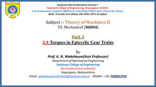
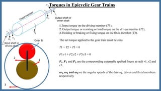
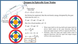
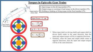
Sanjivani Rural Education Society’s
Sanjivani College of Engineering, Kopargaon-423603
( An Autonomous Institute Affiliated to Savitribai Phule Pune University, Pune)
NAAC ‘A’ Grade Accredited, ISO 9001:2015 Certified
Subject :- Theory of Machines II
T.E. Mechanical (302043)
Unit 3
3.4 Torques in Epicyclic Gear Trains
By
Prof. K. N. Wakchaure(Asst Professor)
Department of Mechanical Engineering
Sanjivani College of Engineering
(An Autonomous Institute)
Kopargaon, Maharashtra
Email: wakchaurekiranmech@Sanjivani.org.in Mobile:- +91-7588025393
Torques in Epicyclic Gear Trains
1
Gear B
2
3
1. Input torque on the driving member (T1),
2. Output torque or resisting or load torque on the driven member (T2),
3. Holding or braking or fixing torque on the fixed member (T3).
The net torque applied to the gear train must be zero.
T1 + T2 + T3 = 0
F1.r1 + F2.r2 + F3.r3 = 0
𝑭 𝟏, 𝑭 𝟐 and 𝑭 𝟑 are the corresponding externally applied forces at radii r1, r2 and
r3.
𝝎 𝟏, 𝝎 𝟐 and 𝝎 𝟑are the angular speeds of the driving, driven and fixed members
respectively
Torques in Epicyclic Gear Trains
the friction be neglected, then the net kinetic energy dissipated by the gear
train must be zero, i.e.
But, for a fixed member, ω3 = 0
T1. 𝝎1 + T2. 𝝎2 = 0
T2 =
− T1. 𝝎1
𝝎2
F1.r1 + F2.r2 + F3.r3 = 0
T1. 𝝎1 + T2. 𝝎2 + T3. 𝝎3 = 0
As T1 + T2 + T3 = 0
T3 = - (T1 +
− T1. 𝝎1
𝝎2
)
T3 = T1(
𝝎1
𝝎2
-1)
• When input shaft (or driving shaft) and output shaft (or
driven shaft) rotate in the same direction, then the
input and output torques will be in opposite directions.
• Similarly, when the input and output shafts rotate in
opposite directions, then the input and output torques
will be in the same direction.
Torques in Epicyclic Gear Trains
T2 =
− T1. 𝝎1
𝝎2
As T1 + T2 + T3 = 0
T3 = T1(
𝝎1
𝝎2
-1)
Input Power =T1. 𝛚1
• When input shaft (or driving shaft) and output shaft (or
driven shaft) rotate in the same direction, then the
input and output torques will be in opposite directions.
• Similarly, when the input and output shafts rotate in
opposite directions, then the input and output torques
will be in the same direction.
1. Input torque on the driving member (T1),
2. Output torque or resisting or load torque on the driven member (T2),
3. Holding or braking or fixing torque on the fixed member (T3).
•Thank You…

3.4 TORQUE ANALYSIS IN GEAR TRAINS

  • 1.
    Sanjivani Rural EducationSociety’s Sanjivani College of Engineering, Kopargaon-423603 ( An Autonomous Institute Affiliated to Savitribai Phule Pune University, Pune) NAAC ‘A’ Grade Accredited, ISO 9001:2015 Certified Subject :- Theory of Machines II T.E. Mechanical (302043) Unit 3 3.4 Torques in Epicyclic Gear Trains By Prof. K. N. Wakchaure(Asst Professor) Department of Mechanical Engineering Sanjivani College of Engineering (An Autonomous Institute) Kopargaon, Maharashtra Email: wakchaurekiranmech@Sanjivani.org.in Mobile:- +91-7588025393
  • 2.
    Torques in EpicyclicGear Trains 1 Gear B 2 3 1. Input torque on the driving member (T1), 2. Output torque or resisting or load torque on the driven member (T2), 3. Holding or braking or fixing torque on the fixed member (T3). The net torque applied to the gear train must be zero. T1 + T2 + T3 = 0 F1.r1 + F2.r2 + F3.r3 = 0 𝑭 𝟏, 𝑭 𝟐 and 𝑭 𝟑 are the corresponding externally applied forces at radii r1, r2 and r3. 𝝎 𝟏, 𝝎 𝟐 and 𝝎 𝟑are the angular speeds of the driving, driven and fixed members respectively
  • 3.
    Torques in EpicyclicGear Trains the friction be neglected, then the net kinetic energy dissipated by the gear train must be zero, i.e. But, for a fixed member, ω3 = 0 T1. 𝝎1 + T2. 𝝎2 = 0 T2 = − T1. 𝝎1 𝝎2 F1.r1 + F2.r2 + F3.r3 = 0 T1. 𝝎1 + T2. 𝝎2 + T3. 𝝎3 = 0 As T1 + T2 + T3 = 0 T3 = - (T1 + − T1. 𝝎1 𝝎2 ) T3 = T1( 𝝎1 𝝎2 -1) • When input shaft (or driving shaft) and output shaft (or driven shaft) rotate in the same direction, then the input and output torques will be in opposite directions. • Similarly, when the input and output shafts rotate in opposite directions, then the input and output torques will be in the same direction.
  • 4.
    Torques in EpicyclicGear Trains T2 = − T1. 𝝎1 𝝎2 As T1 + T2 + T3 = 0 T3 = T1( 𝝎1 𝝎2 -1) Input Power =T1. 𝛚1 • When input shaft (or driving shaft) and output shaft (or driven shaft) rotate in the same direction, then the input and output torques will be in opposite directions. • Similarly, when the input and output shafts rotate in opposite directions, then the input and output torques will be in the same direction. 1. Input torque on the driving member (T1), 2. Output torque or resisting or load torque on the driven member (T2), 3. Holding or braking or fixing torque on the fixed member (T3).
  • 5.