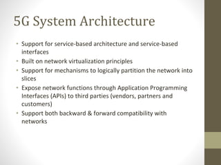
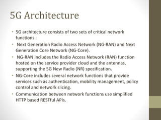
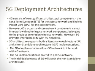
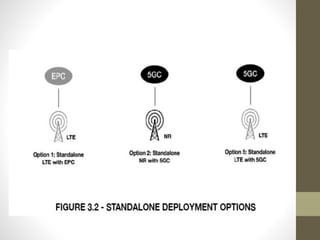
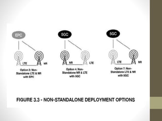
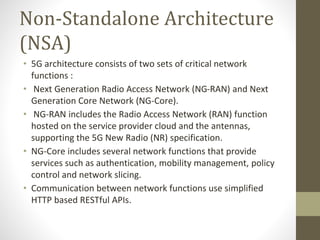
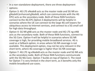
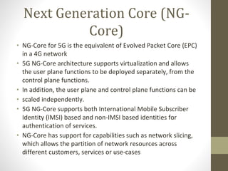
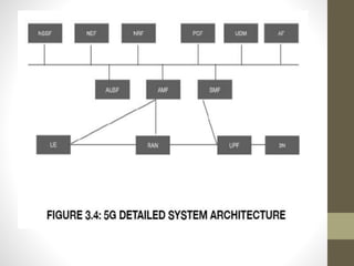
4G / 5G
COMMUNICATION
NETWORKS
BY
ANCHANA V
UNIT II
5G Concepts And
Challenges
5G System Architecture
• Support for service-based architecture and service-based
interfaces
• Built on network virtualization principles
• Support for mechanisms to logically partition the network into
slices
• Expose network functions through Application Programming
Interfaces (APIs) to third parties (vendors, partners and
customers)
• Support both backward & forward compatibility with
networks
5G Architecture
• 5G architecture consists of two sets of critical network
functions :
• Next Generation Radio Access Network (NG-RAN) and Next
Generation Core Network (NG-Core).
• NG-RAN includes the Radio Access Network (RAN) function
hosted on the service provider cloud and the antennas,
supporting the 5G New Radio (NR) specification.
• NG-Core includes several network functions that provide
services such as authentication, mobility management, policy
control and network slicing.
• Communication between network functions use simplified
HTTP based RESTful APIs.
5G Architecture
• The initial 5G launches were based on Non-Standalone (NSA)
architecture - where the 5G radio infrastructure, will still rely
heavily on the 4G core infrastructure for various services.
• The 5G Standalone (SA) architecture will support both the 5G
NR and 5G NG-Core specifications, providing an end-to-end 5G
infrastructure.
5G Deployment Architectures
• 4G consists of two significant architectural components - the
Long Term Evolution (LTE) for the access network and Evolved
Packet Core (EPC) for the core network.
• However, 4G’s access and core network components cannot
interwork with other legacy network components belonging
to the previous generation wireless networks. However, 5G
provides interoperability with 4G networks.
• 5G architecture supports both a Standalane Architecture (SA)
and a Non-Standalone Architecture (NSA) implementations.
• The NSA implementation allows 5G network to interwork
with 4G network.
• The SA implementation is an end-to-end 5G network.
• The initial deployments of 5G will adopt the Non-Standalone
architecture.
Standalone Architecture (SA)
• Standalone architecture uses only one radio access
technology either 4G or 5G.
• The radio cells connect to either a 4G EPC or a 5G Core.
• Architecturally, deploying a standalone solution is simple for
service providers.
• However, it involves a lot of costs Ð as an end-to-end 5G
network infrastructure has to be deployed.
• When a user equipment switches between 5G and 4G
networks, service continuity is achieved through inter-
generation handovers.
Standalone Architecture (SA)
• In a standalone architecture, there are three deployment options:
• Option 1: Wireless service is provided by 4G LTE eNodeB and 4G
EPC. This deployment option is supported by the existing 4G
networks. It supports higher bandwidths of up to 400 Mbps and is
adequate for mobile broadband needs. Some service providers are
marketing this as 5GE (5G Evolution).
• Option 2: Wireless service is provided by 5G NR gNodeB and 5G NG-
Core. This is a full end-to-end 5G service and it will take a few years
for networks to adopt this deployment model.
• Option 5: Wireless service is provided by enhanced 4G LTE ng-
eNodeB (Next Generation eNodeB, which can communicate with
the 5G NG-Core) and 5G NG-Core. This deployment option will be
helpful for service providers during the migration from a full 4G
network to a full 5G network.
Non-Standalone Architecture (NSA)
• 3GPP release 15 standardized the Non-Standalone (NSA) mode of
deployment.
• In NSA mode, 5G networks will be supported by existing 4G
infrastructure.
• For example, a 5G-enabled smartphone will be able to connect to
the network using 5G radio cells for data-throughput improvements
but will still use 4G radio cells for regular low-throughput data
transfers.
• NSA uses a capability called dual-connectivity, defined by the 5G NR
standards where a given UE consumes radio resources provided by
at least two different network points for example, 5G gNB and 4G
eNB.
• NSA enables service providers to deploy 5G, without much of
disruption to their existing networks and services.
• It also helps the service providers to leverage the investments done
in the 4G network
Non-Standalone Architecture
(NSA)
• 5G architecture consists of two sets of critical network
functions :
• Next Generation Radio Access Network (NG-RAN) and Next
Generation Core Network (NG-Core).
• NG-RAN includes the Radio Access Network (RAN) function
hosted on the service provider cloud and the antennas,
supporting the 5G New Radio (NR) specification.
• NG-Core includes several network functions that provide
services such as authentication, mobility management, policy
control and network slicing.
• Communication between network functions use simplified
HTTP based RESTful APIs.
• In a non-standalone deployment, there are three deployment
• options:
• Option 3: 4G LTE eNodeB acts as the master node and 5G NR en-
gNodeB (enhanced gNodeB, which can communicate with the 4G
EPC) acts as the secondary node. Both of these RAN functions
connect to the 4G EPC.Option 3 deployments will be helpful in
scenarios where the UE can connect to the large 4G cell towers for
ubiquitous access to Internet services, and connect to a 5G small cell
for high data throughput.
• Option 4: 5G NR gNB acts as the master node and 4G LTE ng-eNB
acts as the secondary node. Both of these RAN functions, connect to
the 5G Core. Option 4 will be helpful in scenarios where 5G NR
coverage is high, for providing mobile broadband services. 4G is
used as a fallback option, in areas where 5G NR coverage is not
available. This deployment option, may not be very relevant in the
short term, where 4G coverage is higher than 5G NR coverage.
• Option 7: 4G LTE ng-eNodeB acts as the master node and 5G NR acts
as the secondary node. Both of these RAN functions communicate
with the 5G NG-Core. Option 7 builds on top of Option 5. The need
for Option 7 is very limited in the short term, as it beneÞts only the
mobile broadband use-cases.
Next Generation Core (NG-
Core)
• NG-Core for 5G is the equivalent of Evolved Packet Core (EPC)
in a 4G network
• 5G NG-Core architecture supports virtualization and allows
the user plane functions to be deployed separately, from the
control plane functions.
• In addition, the user plane and control plane functions can be
• scaled independently.
• 5G NG-Core supports both International Mobile Subscriber
Identity (IMSI) based and non-IMSI based identities for
authentication of services.
• NG-Core has support for capabilities such as network slicing,
which allows the partition of network resources across
different customers, services or use-cases
Network Functions in NG-
Core
• 1. Authentication Server Function (AUSF)
• 2. Access and Mobility Management Function (AMF)
• 3. Data Network (DN)
• 4. Network Exposure Function (NEF)
• 5. Network Repository Function (NRF)
• 6. Network Slice Selection Function (NSSF)
• 7. Policy Control Function (PCF)
• 8. Session Management Function (SMF)
• 9. UniÞed Data Management (UDM)
• 10. User Plane Function (UPF)
• 11. Application Function (AF)
Authentication Server
Function (AUSF) -
• AUSF acts as an authentication server, performing UE
authentication using Extensible Authentication Protocol (EAP)
• EAP is a popular protocol used in WiFi networks for
authenticating WiFi clients.
• In the 4G network, AUSF function was part of the Home
Subscriber Server (HSS) function.
Access and Mobility
Management Function (AMF)
• Responsible for connection management, registration
management and mobility management (handling of
reachability and idle/active mode mobility state).
• It also takes care of access authentication and authorization.
• AMF also supports Lawful intercept function for AMF events.
In the 4G network, this function was part of the Mobility
Management Entity (MME).
•Data Network (DN) –
• DN offers operator services, internet access and third party
services.
Network Exposure Function
(NEF)
• NEF is a proxy or API aggregation point for the core network
and provides security when services or external application
functions access the 5G Core nodes.
• This is a new function introduced in 5G architecture.
Network Repository Function
(NRF)
• NRF supports service discovery, and maintains/provides
profiles of network function instances.
• This is a new function introduced in 5G architecture.
Network Slice Selection
Function (NSSF) -
• NSSF supports the selection of network slice instances to
serve the User Equipment (UE), based on the Network Slice
Selection Assignment Information (NSSAIs) configured or
allowed for a given UE.
• This is a new function introduced in 5G architecture.
Policy Control Function (PCF)
• PCF provides a unified policy framework and shares policy
rules to control plane functions, to enforce them.
• It also accesses subscription information relevant for policy
decisions from the Unified Data Repository (UDR).
• PCF was part of the PCRF function in the 4G network.
Session Management
Function (SMF) -
• SMF provides session management, UE IP address allocation
& management and DHCP functions.
• It also provides traffic steering configuration for User Plane
Function (UPF) for proper traffic routing.
• SMF function was split between the MME and Packet
Gateway (PGW) function in 4G network.
Unified Data Management
(UDM)
• UDM provides Authentication and Key Agreement (AKA)
credentials, user identification handling, access authorization
and subscription management functions.
• UDM was part of the HSS functionality in the 4G
architecture.
User Plane Function (UPF)
• UPF provides packet routing and forwarding functions. In
addition, it also handles QoS services.
• UPF function was split between Serving Gateway (SGW) and
PGW in the 4G architecture.
• Separating the user plane from the control plane in both
SGW/PGW, enables the service providers to deploy the UPF
closer to the network edge.
• In 5G, UPF function can be deployed at the network edge, in
addition to the network core, to improve the network
performance and to reduce latency.
Application Function (AF) -
• AF function is similar to the AF function in the 4G network.
• It interacts with the 5G core to provide services such as
application influence on traffic routing, accessing Network
Exposure Function (NEF) and interacting with policy
framework for policy control.
Control and User Plane
Separation in 5G Core
• CUPS stands for Control and User Plane Separation. I
• t was introduced by 3GPP, for Evolved Packet Core (EPC) as
part of their Release 14 specifications.
CUPS in 4G architecture
• CUPS was originally introduced in the 4G Evolved Packet Core
(EPC) architecture.
• EPC with CUPS support separates the control plane function
from the user plane function in the network.
• Network functions within 4G EPC such as Packet Gateway
(PGW), Serving Gateway (SGW) and Traffic Detection
Function (TDF), were split into control plane and user plane
functions.
•
• 5G adopts CUPS based architecture for the 5G Core.
• 5G Core has a distinct User Plane Function (UPF) that
handles all of the user-plane functions performed by SGW-U
and PGW-U in 4G EPC, 5G's control plane functions are
distributed across different network functions such as
Authentication Server Function (AUSF), User Data
Management (UDM), Policy and Charging Function (PCF) and
Session Management Function (SMF).
• This gives a lot of flexibility for the service providers to
decide the network functions which have to be deployed at
the edge of the network versus the core of the network.
• Since 5G supports cloud-native network services, it becomes
easy for the vendors and service providers to implement
CUPS in the 5G network architecture (when compared to the
4G network).
Communication approach for Core
Network
• Functions 5G architecture brings a significant difference in
the way in which core network functions communicate with
each other.
• 5G architecture supports two approaches for the
communication between the core network functions –
1. Point to Point
2. Service Based Architecture (SBA)
Point to Point
• In the traditional 4G network, core network functions
communicated with each other based on reference points
and interfaces connecting those reference points.
• The communication between core network functions in 4G
network was point to point.
• That is, there will always be one sender and one receiver for
any communication between the 4G network elements.
• 5G network also supports the traditional point-to-point
architectural approach.
Service based Architecture
(SBA).
• In addition to supporting the Point-to-Point architecture, SBA
is a new approach introduced with the 5G network
architecture.
• In SBA, the core network functions are either producers or
consumers of various network services.
• In the producer-consumer model, there can be one producer
and multiple consumers. They communicate with each other
using Restful APIs.
• 5G architecture provides a framework for different network
functions to effectively produce and consume services.
• There are two types of communication models supported by
the SBA:
• Request-Response model: This is used for exchanging
simple information requests and responses between the
network functions.
• This model uses synchronous requests and responses. For
example, authentication of a subscriber in the network.
• Subscribe-Notify model : This is used for requests that would
take a long time to process or for getting notified upon an
event.
Next Gen Radio Access
Networks (NG-RAN)
• In 5G, the RAN architecture evolved further and is called the
Next Generation Radio Access Networks (5G NG-RAN).
• 5G NG-RAN provides packet processing, baseband processing.
radio signals processing and radio control functions.
• NG-RAN provides capability to configure and scale RAN nodes
dynamically through software.
• The signaling and data transport network (i.e., the control plane
and user plane functions) of the NG-RAN are logically separated.
• NG-RAN supports seamless management of radio resources,
including mobility of radio resources.
• NG-RAN architecture provides the flexibility to deploy RAN nodes
based on spectrum efficiency and performance requirements.
5G NG-RAN node functions
• Next generation eNodeB (ng-eNB)
• Next generation NodeB (gNB)
Next Generation E-NodeB
(ng-eNB)
• Next Generation E-NodeB (ng-eNB) is an enhanced version of
the 4G eNodeB which connects a 5G user equipment to the
5G Core network using enhanced 4G LTE air interfaces.
• The user equipment would use the 4G LTE radio resources to
connect to the ng-eNB.
• ng-eNB provides E-UTRAN user plane and control plane
protocol terminations towards the user equipment and
connected via the NG interface to theNG-Core.
• During the transition to 5G, there is going to be lot more 4G
networks when compared to 5G networks. So, there may be
localities without any 5G coverage.
• In such geographies, ng-eNBs would allow the 5G subscriber
to connect to the network using 4G air interface.
Next Generation NodeB(gNB)
• Next Generation NodeB (gNB) is the radio node, which is
equivalent of the eNB in the 4G architecture.
• gNB connects the 5G capable user equipment using the 5G
New Radio (NR) air interfaces.
• gNB provides 5G New Radio (NR) user plane and control
plane protocol terminations towards the user equipment and
connected via the NG interface to the NG-Core.
gNB Functional Modules
1. Centralized Unit (CU)
2. Distributed Unit (DU)
3. Radio Unit (RU).
• The Baseband Unit (BBU) function from the traditional 4G
architecture is now divided into CU and DU, in a 5G
architecture. This gives the flexibility for the service
providers to selectively deploy BBU's CU and DU functions
either near the cellsite or in the central office/Edge location.
• gNB-CU is responsible for mobility control. radio resources
management and session management.
• gNB-DU provides Media Access Control (MAC) and physical
layer services (PHY). The functionality split between the CU
and DU is implementation dependant.
• Radio Unit (RU) is the radio node. The Remote Radio Head
(RRH) function from the 4G architecture is now called the RU,
in a 5G network.
NG-Deployment Options
• There are 3 options available to split the functions across
RRH and the BBU
1. Cellsite RAN
2. Split RAN
3. Centralised RAN
Cellsite RAN
• In this deployment mode, all the 3 functions RU, CU and DU
are deployed at the cellsite near the tower.
• This could also be a monolithic deployment where all the 3
functions are present in a physical Base station.
• Cellsite RAN helps the service provider to guarantee ultra low
latencies (<1ms), when the cellsite does not have a fiber link
in the fronthaul.
• Cellsite RAN deployment is ideal for industrial automation
use-cases
Split RAN:
• In this deployment mode, the DU function is deployed along
with the RU and the CU function is deployed at the Central
Office/ Edge location.
• The Centralized Unit (CU) can further be split into CU- User
Plane (UP) and CU-Control Plane (CU-CP).
• Optionally, the edge location can also host a Multi- access
Edge Computing (MEC) cluster.
• This type of deployment is suitable for applications such as
Augmented Reality or Virtual Reality.
Centralized RAN
• In this deployment mode, the CU and the DU functions are
located at the edge.
• They are connected to the cellsite via high-speed or low-
speed links, supporting a latency of < 10 ms.
• This type of deployment is suitable for applications such as
Enhanced Mobile Broadband (eMBB).
5G New Radio (5G NR)
• One of the significant changes to the 5G architecture is the radio
specification. 5G introduces a new radio specification called 5G
New Radio (5G NR). Some of the key changes to the radio function
in 5G are:
• Spectrum: 5G supports a wide range of spectrums from low bands
below 1 GHz, to mid bands from 1 GHz to 6 GHZ, to high bands 24 /
30 GHz to 300 GHz. This high band is called as millimeter-wave.
• Latency: 5G NR supports lower latencies less than 10 milliseconds
• Beamforming: 5G NR supports a large number of multiple input
multiple output (MIMO) antennas, which would allow it to work in
a high interference environment through a technique called
"beamforming". It enables 5G radios to provide both coverage and
capacity.
• Interworking with 4G: Coexistence with LTE (by supporting LTE
NR), by bringing an overlay network. in cases where 5G coverage is
not available.
Technologies accelerating
5G Radio
• 1. MIMO
• MIMO stands for Multiple Input and Multiple Output, where
several small antennas are grouped together at the
transmitter and at the receiver.
• Before the introduction of MIMO, radio devices in wireless
networks used a single antenna at the source and a single
antenna at the destination for sending and receiving signals.
• When signals had to penetrate through walls and objects in
between, they get scattered and lost before reaching the
destination.
• This would result in errors and also affects the network
performance, especially the speed.
• After the introduction of MIMO technology, radio devices
were able to send or receive multiple signals at the same
time - to minimize the errors and to improve the speed.
• MIMO uses a technique called multi-path propagation, where
the radio signals are transmitted via two or more paths to reach
the destination.
• Multi-path propagation approach increases the chances of
signals reaching the receiver.
• When signals are sent via multiple paths, the overall strength of
the signal received by the radio device is equal to the sum of all
the signals received by the different antennas.
2. Massive MIMO
• 5G adopts massive MIMO technology where a few tens to
several hundreds of antennas are used for propagating radio
signals.
• The Massive MIMO enabled radio devices use
algorithms to calculate the best possible transmission route
through the air, to reach the receivers without any
interference or with reduced interference.
3. Coordinated Multipoint
(CoMP)
• Technique used to improve radio performance, at cell edges by utilising
the capability of more than one base station to enable the
communication.
• Using CoMP, radio access nodes dynamically coordinate the
transmission and reception of signals from the UE to multiple base
stations
Advantages:
1. Helps the service provider to improve the utilization of
network resources. For example, data can be passed
through a base station which is not loaded.
2. User notices lesser call drops, as several cell sites
come together to provide service to the user
User notices higher bandwidth, as multiple base
stations serve the user, at a given time. The impact of
the interference gets reduced and interference is used
constructively
Small Cells
• 5G, because of the reliance on mmWave technology (which
has a shorter wavelength) requires several thousands of
small cells be deployed around the cities.
• Small Cells are mini base stations that handle the radio
signals, like the mobile towers.
• Small Cells require very minimal power and space, unlike the
large mobile towers in the neighbourhood.
• Small Cells can be installed on the top of a light pole or a
building. Small Cells are not new to the wireless world.
Three categories of small cells that exist today:
1. Femtocells –
• Femtocells help the operators in quickly
solving the network coverage problem.
• It takes a very long time for a service provider to install a
mobile tower.
• However, it takes only a few days to power up
a femtocell in the network.
• So, if there is a residential or an enterprise customer that
requires extended wireless coverage, the operator can
quickly deploy a Femtocell.
2. Picocells –
• Picocells are similar to Femtocells in terms of functionality.
• However, their coverage area is 100 – 500 meters.
• Also, they can support 32 – 64 users at a time.
• Picocells are well suited for small enterprise applications.
3. Microcells –
• Microcells are designed for providing wireless coverage to a
large geographic area and suited for providing network
coverage to outdoor applications such as smart
communities.
• Microcells provide coverage for a distance between 500
meters
and 2.5 kilometers.
• Microcells can support nearly 200 users at a time.
Network Functions Virtualization
(NFV)
• Network Functions Virtualization (NFV) transforms the
network architecture of service providers, by borrowing IT
virtualization techniques to virtualize network functions and
run them as software on top of standard servers, storages
and switches.
• NFV allows service providers to increase the utilization of
their hardware, reduce operational costs and reduce the
time it takes to activate a service for the customer.
Need for NFV
• Cost Savings
• Speed to Market
• Lesser Downtime during Maintenance
NFV Architecture
• Network Functions Virtualization Infrastructure (NFVI) -
NFVI consists of the physical compute, storage and network
hardware resources. VIM partitions those resources and
makes them available as virtual compute, virtual storage and
virtual network instances. NFVI provides the virtual
execution environment for the Virtual Network Functions
(VNFs).
• Management and Network Orchestrator (MANO) - NFV
MANO includes three distinct functions - Virtual
Infrastructure Manager (VIM), VNF Manager (VNFM) and
the NFV Orchestrator (NFVO).
• Virtual Infrastructure Manager (VIM) – NFVI is managed
by Virtualized Infrastructure Manager (VIM). VIM is used for
partitioning the physical hardware resources and for
managing the virtual infrastructure. OpenStack is a popular
open source VIM. OpenStack is capable of managing both
the virtual and physical infrastructure in a hybrid cloud
environment.
• VNF Manager (VNFM) - VNFM is typically provided by the
VNF vendor to manage the VNFs that run on the NFVI.
VNFMs perform lifecycle management (LCM) of the VNFs -
which includes starting/stopping VNFs, automatically
restarting a VNF when it goes down, software upgrade/
downgrade and scale-in/scale-out of VNFs based on load.
There are two types of VNFMs available in the market today
– Generic VNFM (which can manage multiple-types of
VNFs) and Specific VNFM (which can manage only a
specific type of VNF). Specific VNFMs are typically provided
by network equipment vendors who supply the VNFs.
• NFV Orchestrator (NFVO) – NFV Orchestrator is the
controller of all the workflows in an NFV architecture. NFVO
coordinates across multiple entities such as OSS/BSS,
VNFM and VIM.
• NFVO often performs two distinct roles:
Resource Orchestration – As a resource
orchestrator, NFVO coordinates with VIM for tenant
space creation, coordinates with VNFM for starting a
VNF instance and loading it with appropriate configuration.
Service Orchestration – As a service orchestrator,
NFVO is responsible for the creation of network
services. NFVO coordinates with OSS/BSS and
VNFMs for downloading service-related configuration
to the VNFs.
• Service Catalogue – Service Catalogue includes all of the
meta data and descriptors related to the VNFs. For example,
service catalogue would include information such as CPU,
memory and storage resource requirements of a VNF.
•
• Element Management Systems (EMS) - EMS is provided
by the VNF vendor to support FCAPS (Fault, Configuration,
Accounting, Performance and Security management)
functions. When a VNF instance is instantiated in the cloud
environment, EMS is responsible for downloading the
‘default’ configuration supplied by the vendor to the VNFs.
• Virtual Network Function (VNF) - VNF is the software
implementation of the hardware-based network function.
VNFs run on the NFVI, to deliver network services.
Virtualized RAN, Virtualized Evolved Packet Core,
Virtualized Firewalls, Virtualized Load Balancers, Virtualized
Routers and Virtualized WAN Optimizers are some of the
popular VNFs in the market, today.
• VNFs in the 5G network, in a non-standalone
architecture are:
• Virtualization of Radio Access network (vRAN)
• Virtualization of Evolved Packet Core (vEPC)
Virtualized RAN (vRAN)
• In a 5G network, BBU function is split further into
Centralised unit (CU) and Distributed unit (DU).
• The service provider gets to choose whether to deploy the entire BBU or
just the CU or DU at the network edge.
• 5G architecture supports virtualization of the BBU function.
• When multiple instances of BBUs are run in a cluster it is called as BBU pool.
• RRH function, which is now called as the Radio Unit (RU) in a 5G network,
continues to reside in the cellsite.
• The Virtualized BBU performs functions such as baseband
processing, radio resource management and mobility
management, in addition to providing application security.
• RU is connected to Virtual BBUs using Optical Fibre Front haul links, for
maximum performance.
• Each RU can either connect to a dedicated BBU or there can be a switch in
the cloud that efficiently distributes RU connections across
a pool of available BBUs.
• The latter approach helps in efficiently managing BBU resources.
Advantages of hosting BBUs in a virtualized cloud
environment:
• Carving out the BBU functionality from the base station and moving it to
the Central Office helps the service providers to reduce the cost of
deploying the cell sites.
• The cell site has limited power and processing capacity for the BBU. By
moving the BBU function to Central office, service providers get access to
extra power and processing capacity .
• Resources can be allocated on-demand and can be shared across
multiple RUs. This results in improved resource utilization and a
reduction in power consumption.
• Same server(s) can also be used to host additional services such as
content caching, deep packet inspection and analytics. This would
increase the speed of application services .
• When BBU function is virtualized, it reduces the downtime of network
services when there are faults.
Virtualized Evolved Packet
Core (vEPC)
• Virtual Evolved Packet Core (vEPC) is functionally similar to
the physical EPC.
• There are two methods in which a Virtualized Evolved Packet Core
(EPC) can be deployed:
1. An all-in-one Virtual EPC (vEPC)
2. Standalone instances of MME, PGW, SGW, HSS and
PCRF.
• In an all-in-one deployment model, it is easy to manage the vEPC
instance as one entity. However, it lacks mechanisms to individually
scale one or more services.
• In a deployment with standalone instances of the vEPC
components, the service provider can individually scale the
components.
• A Virtual EPC may have one or more VMs for each of the components. For
example, a PCRF service may have multiple micro-services. Each of these
microservices may run on a separate VM or a Container, on the telco cloud.
• A subscriber’s session state information in a physical EPC may be stored in
RAM or transient memory in the hardware. A physical EPC achieves
highavailability and reliability by deploying multiple physical instances of the
EPC hardware. However, in a Virtual EPC deployment, the vEPC instance may
store the session state information in a reliable
database, for session continuity during fail-overs .
• A physical EPC relies on the underlying hardware for dataplane acceleration.
A Virtual EPC relies on software based dataplane acceleration technologies.
• In a vEPC, the dataplane is scaled by using
technologies such as SRIOV (Single Root – Input/ Output Virtualization).
• SRIOV partitions a physical network interface card into multiple virtual
network interface cards (vNICs) and provides direct access to the physical
NIC, bypassing the hypervisor layer.
• Virtual EPC also leverages several advancements in the data plane
acceleration such as the Data Plane Development Kit (DPDK) and FD.io (fast
data input/ output).
Benefits of NFV
• Increases the utilization of the hardware in the network, by
eliminating special purpose physical network functions
• Reduces operational costs by standardizing the management
of different network functions
• Provides flexibility to scale-in / scale-out the virtual
network functions based on the network load and
infrastructure demand .
• Helps service providers to implement a Continuous
Integration / Continuous Deployment (CI/CD) pipeline
to rollout new updates / changes to the network -
without a huge network down time.
Role of NFV in 5G networks
• Enables Virtualization of Cloud RAN
• Simplifies the creation of Network Slices
• Makes the 5G network elastic and scalable
• Enables the 5G network to support a “service-based”
architecture
• Improves the agility and simplifies network upgrades

45 5G COMMUNICATION NETWORKS ECE PROF ELECTIVE.pptx

  • 1.
  • 2.
    UNIT II 5G ConceptsAnd Challenges
  • 3.
    5G System Architecture •Support for service-based architecture and service-based interfaces • Built on network virtualization principles • Support for mechanisms to logically partition the network into slices • Expose network functions through Application Programming Interfaces (APIs) to third parties (vendors, partners and customers) • Support both backward & forward compatibility with networks
  • 4.
    5G Architecture • 5Garchitecture consists of two sets of critical network functions : • Next Generation Radio Access Network (NG-RAN) and Next Generation Core Network (NG-Core). • NG-RAN includes the Radio Access Network (RAN) function hosted on the service provider cloud and the antennas, supporting the 5G New Radio (NR) specification. • NG-Core includes several network functions that provide services such as authentication, mobility management, policy control and network slicing. • Communication between network functions use simplified HTTP based RESTful APIs.
  • 6.
    5G Architecture • Theinitial 5G launches were based on Non-Standalone (NSA) architecture - where the 5G radio infrastructure, will still rely heavily on the 4G core infrastructure for various services. • The 5G Standalone (SA) architecture will support both the 5G NR and 5G NG-Core specifications, providing an end-to-end 5G infrastructure.
  • 7.
    5G Deployment Architectures •4G consists of two significant architectural components - the Long Term Evolution (LTE) for the access network and Evolved Packet Core (EPC) for the core network. • However, 4G’s access and core network components cannot interwork with other legacy network components belonging to the previous generation wireless networks. However, 5G provides interoperability with 4G networks. • 5G architecture supports both a Standalane Architecture (SA) and a Non-Standalone Architecture (NSA) implementations. • The NSA implementation allows 5G network to interwork with 4G network. • The SA implementation is an end-to-end 5G network. • The initial deployments of 5G will adopt the Non-Standalone architecture.
  • 8.
    Standalone Architecture (SA) •Standalone architecture uses only one radio access technology either 4G or 5G. • The radio cells connect to either a 4G EPC or a 5G Core. • Architecturally, deploying a standalone solution is simple for service providers. • However, it involves a lot of costs Ð as an end-to-end 5G network infrastructure has to be deployed. • When a user equipment switches between 5G and 4G networks, service continuity is achieved through inter- generation handovers.
  • 10.
    Standalone Architecture (SA) •In a standalone architecture, there are three deployment options: • Option 1: Wireless service is provided by 4G LTE eNodeB and 4G EPC. This deployment option is supported by the existing 4G networks. It supports higher bandwidths of up to 400 Mbps and is adequate for mobile broadband needs. Some service providers are marketing this as 5GE (5G Evolution). • Option 2: Wireless service is provided by 5G NR gNodeB and 5G NG- Core. This is a full end-to-end 5G service and it will take a few years for networks to adopt this deployment model. • Option 5: Wireless service is provided by enhanced 4G LTE ng- eNodeB (Next Generation eNodeB, which can communicate with the 5G NG-Core) and 5G NG-Core. This deployment option will be helpful for service providers during the migration from a full 4G network to a full 5G network.
  • 11.
    Non-Standalone Architecture (NSA) •3GPP release 15 standardized the Non-Standalone (NSA) mode of deployment. • In NSA mode, 5G networks will be supported by existing 4G infrastructure. • For example, a 5G-enabled smartphone will be able to connect to the network using 5G radio cells for data-throughput improvements but will still use 4G radio cells for regular low-throughput data transfers. • NSA uses a capability called dual-connectivity, defined by the 5G NR standards where a given UE consumes radio resources provided by at least two different network points for example, 5G gNB and 4G eNB. • NSA enables service providers to deploy 5G, without much of disruption to their existing networks and services. • It also helps the service providers to leverage the investments done in the 4G network
  • 13.
    Non-Standalone Architecture (NSA) • 5Garchitecture consists of two sets of critical network functions : • Next Generation Radio Access Network (NG-RAN) and Next Generation Core Network (NG-Core). • NG-RAN includes the Radio Access Network (RAN) function hosted on the service provider cloud and the antennas, supporting the 5G New Radio (NR) specification. • NG-Core includes several network functions that provide services such as authentication, mobility management, policy control and network slicing. • Communication between network functions use simplified HTTP based RESTful APIs.
  • 14.
    • In anon-standalone deployment, there are three deployment • options: • Option 3: 4G LTE eNodeB acts as the master node and 5G NR en- gNodeB (enhanced gNodeB, which can communicate with the 4G EPC) acts as the secondary node. Both of these RAN functions connect to the 4G EPC.Option 3 deployments will be helpful in scenarios where the UE can connect to the large 4G cell towers for ubiquitous access to Internet services, and connect to a 5G small cell for high data throughput. • Option 4: 5G NR gNB acts as the master node and 4G LTE ng-eNB acts as the secondary node. Both of these RAN functions, connect to the 5G Core. Option 4 will be helpful in scenarios where 5G NR coverage is high, for providing mobile broadband services. 4G is used as a fallback option, in areas where 5G NR coverage is not available. This deployment option, may not be very relevant in the short term, where 4G coverage is higher than 5G NR coverage. • Option 7: 4G LTE ng-eNodeB acts as the master node and 5G NR acts as the secondary node. Both of these RAN functions communicate with the 5G NG-Core. Option 7 builds on top of Option 5. The need for Option 7 is very limited in the short term, as it beneÞts only the mobile broadband use-cases.
  • 15.
    Next Generation Core(NG- Core) • NG-Core for 5G is the equivalent of Evolved Packet Core (EPC) in a 4G network • 5G NG-Core architecture supports virtualization and allows the user plane functions to be deployed separately, from the control plane functions. • In addition, the user plane and control plane functions can be • scaled independently. • 5G NG-Core supports both International Mobile Subscriber Identity (IMSI) based and non-IMSI based identities for authentication of services. • NG-Core has support for capabilities such as network slicing, which allows the partition of network resources across different customers, services or use-cases
  • 17.
    Network Functions inNG- Core • 1. Authentication Server Function (AUSF) • 2. Access and Mobility Management Function (AMF) • 3. Data Network (DN) • 4. Network Exposure Function (NEF) • 5. Network Repository Function (NRF) • 6. Network Slice Selection Function (NSSF) • 7. Policy Control Function (PCF) • 8. Session Management Function (SMF) • 9. UniÞed Data Management (UDM) • 10. User Plane Function (UPF) • 11. Application Function (AF)
  • 18.
    Authentication Server Function (AUSF)- • AUSF acts as an authentication server, performing UE authentication using Extensible Authentication Protocol (EAP) • EAP is a popular protocol used in WiFi networks for authenticating WiFi clients. • In the 4G network, AUSF function was part of the Home Subscriber Server (HSS) function.
  • 19.
    Access and Mobility ManagementFunction (AMF) • Responsible for connection management, registration management and mobility management (handling of reachability and idle/active mode mobility state). • It also takes care of access authentication and authorization. • AMF also supports Lawful intercept function for AMF events. In the 4G network, this function was part of the Mobility Management Entity (MME). •Data Network (DN) – • DN offers operator services, internet access and third party services.
  • 20.
    Network Exposure Function (NEF) •NEF is a proxy or API aggregation point for the core network and provides security when services or external application functions access the 5G Core nodes. • This is a new function introduced in 5G architecture.
  • 21.
    Network Repository Function (NRF) •NRF supports service discovery, and maintains/provides profiles of network function instances. • This is a new function introduced in 5G architecture.
  • 22.
    Network Slice Selection Function(NSSF) - • NSSF supports the selection of network slice instances to serve the User Equipment (UE), based on the Network Slice Selection Assignment Information (NSSAIs) configured or allowed for a given UE. • This is a new function introduced in 5G architecture.
  • 23.
    Policy Control Function(PCF) • PCF provides a unified policy framework and shares policy rules to control plane functions, to enforce them. • It also accesses subscription information relevant for policy decisions from the Unified Data Repository (UDR). • PCF was part of the PCRF function in the 4G network.
  • 24.
    Session Management Function (SMF)- • SMF provides session management, UE IP address allocation & management and DHCP functions. • It also provides traffic steering configuration for User Plane Function (UPF) for proper traffic routing. • SMF function was split between the MME and Packet Gateway (PGW) function in 4G network.
  • 25.
    Unified Data Management (UDM) •UDM provides Authentication and Key Agreement (AKA) credentials, user identification handling, access authorization and subscription management functions. • UDM was part of the HSS functionality in the 4G architecture.
  • 26.
    User Plane Function(UPF) • UPF provides packet routing and forwarding functions. In addition, it also handles QoS services. • UPF function was split between Serving Gateway (SGW) and PGW in the 4G architecture. • Separating the user plane from the control plane in both SGW/PGW, enables the service providers to deploy the UPF closer to the network edge. • In 5G, UPF function can be deployed at the network edge, in addition to the network core, to improve the network performance and to reduce latency.
  • 27.
    Application Function (AF)- • AF function is similar to the AF function in the 4G network. • It interacts with the 5G core to provide services such as application influence on traffic routing, accessing Network Exposure Function (NEF) and interacting with policy framework for policy control.
  • 28.
    Control and UserPlane Separation in 5G Core • CUPS stands for Control and User Plane Separation. I • t was introduced by 3GPP, for Evolved Packet Core (EPC) as part of their Release 14 specifications.
  • 29.
    CUPS in 4Garchitecture • CUPS was originally introduced in the 4G Evolved Packet Core (EPC) architecture. • EPC with CUPS support separates the control plane function from the user plane function in the network. • Network functions within 4G EPC such as Packet Gateway (PGW), Serving Gateway (SGW) and Traffic Detection Function (TDF), were split into control plane and user plane functions. •
  • 30.
    • 5G adoptsCUPS based architecture for the 5G Core. • 5G Core has a distinct User Plane Function (UPF) that handles all of the user-plane functions performed by SGW-U and PGW-U in 4G EPC, 5G's control plane functions are distributed across different network functions such as Authentication Server Function (AUSF), User Data Management (UDM), Policy and Charging Function (PCF) and Session Management Function (SMF). • This gives a lot of flexibility for the service providers to decide the network functions which have to be deployed at the edge of the network versus the core of the network. • Since 5G supports cloud-native network services, it becomes easy for the vendors and service providers to implement CUPS in the 5G network architecture (when compared to the 4G network).
  • 31.
    Communication approach forCore Network • Functions 5G architecture brings a significant difference in the way in which core network functions communicate with each other. • 5G architecture supports two approaches for the communication between the core network functions – 1. Point to Point 2. Service Based Architecture (SBA)
  • 32.
    Point to Point •In the traditional 4G network, core network functions communicated with each other based on reference points and interfaces connecting those reference points. • The communication between core network functions in 4G network was point to point. • That is, there will always be one sender and one receiver for any communication between the 4G network elements. • 5G network also supports the traditional point-to-point architectural approach.
  • 33.
    Service based Architecture (SBA). •In addition to supporting the Point-to-Point architecture, SBA is a new approach introduced with the 5G network architecture. • In SBA, the core network functions are either producers or consumers of various network services. • In the producer-consumer model, there can be one producer and multiple consumers. They communicate with each other using Restful APIs. • 5G architecture provides a framework for different network functions to effectively produce and consume services.
  • 34.
    • There aretwo types of communication models supported by the SBA: • Request-Response model: This is used for exchanging simple information requests and responses between the network functions. • This model uses synchronous requests and responses. For example, authentication of a subscriber in the network. • Subscribe-Notify model : This is used for requests that would take a long time to process or for getting notified upon an event.
  • 35.
    Next Gen RadioAccess Networks (NG-RAN) • In 5G, the RAN architecture evolved further and is called the Next Generation Radio Access Networks (5G NG-RAN). • 5G NG-RAN provides packet processing, baseband processing. radio signals processing and radio control functions. • NG-RAN provides capability to configure and scale RAN nodes dynamically through software. • The signaling and data transport network (i.e., the control plane and user plane functions) of the NG-RAN are logically separated. • NG-RAN supports seamless management of radio resources, including mobility of radio resources. • NG-RAN architecture provides the flexibility to deploy RAN nodes based on spectrum efficiency and performance requirements.
  • 36.
    5G NG-RAN nodefunctions • Next generation eNodeB (ng-eNB) • Next generation NodeB (gNB)
  • 37.
    Next Generation E-NodeB (ng-eNB) •Next Generation E-NodeB (ng-eNB) is an enhanced version of the 4G eNodeB which connects a 5G user equipment to the 5G Core network using enhanced 4G LTE air interfaces. • The user equipment would use the 4G LTE radio resources to connect to the ng-eNB. • ng-eNB provides E-UTRAN user plane and control plane protocol terminations towards the user equipment and connected via the NG interface to theNG-Core. • During the transition to 5G, there is going to be lot more 4G networks when compared to 5G networks. So, there may be localities without any 5G coverage. • In such geographies, ng-eNBs would allow the 5G subscriber to connect to the network using 4G air interface.
  • 38.
    Next Generation NodeB(gNB) •Next Generation NodeB (gNB) is the radio node, which is equivalent of the eNB in the 4G architecture. • gNB connects the 5G capable user equipment using the 5G New Radio (NR) air interfaces. • gNB provides 5G New Radio (NR) user plane and control plane protocol terminations towards the user equipment and connected via the NG interface to the NG-Core.
  • 39.
    gNB Functional Modules 1.Centralized Unit (CU) 2. Distributed Unit (DU) 3. Radio Unit (RU).
  • 40.
    • The BasebandUnit (BBU) function from the traditional 4G architecture is now divided into CU and DU, in a 5G architecture. This gives the flexibility for the service providers to selectively deploy BBU's CU and DU functions either near the cellsite or in the central office/Edge location. • gNB-CU is responsible for mobility control. radio resources management and session management. • gNB-DU provides Media Access Control (MAC) and physical layer services (PHY). The functionality split between the CU and DU is implementation dependant. • Radio Unit (RU) is the radio node. The Remote Radio Head (RRH) function from the 4G architecture is now called the RU, in a 5G network.
  • 41.
    NG-Deployment Options • Thereare 3 options available to split the functions across RRH and the BBU 1. Cellsite RAN 2. Split RAN 3. Centralised RAN
  • 42.
    Cellsite RAN • Inthis deployment mode, all the 3 functions RU, CU and DU are deployed at the cellsite near the tower. • This could also be a monolithic deployment where all the 3 functions are present in a physical Base station. • Cellsite RAN helps the service provider to guarantee ultra low latencies (<1ms), when the cellsite does not have a fiber link in the fronthaul. • Cellsite RAN deployment is ideal for industrial automation use-cases
  • 43.
    Split RAN: • Inthis deployment mode, the DU function is deployed along with the RU and the CU function is deployed at the Central Office/ Edge location. • The Centralized Unit (CU) can further be split into CU- User Plane (UP) and CU-Control Plane (CU-CP). • Optionally, the edge location can also host a Multi- access Edge Computing (MEC) cluster. • This type of deployment is suitable for applications such as Augmented Reality or Virtual Reality.
  • 44.
    Centralized RAN • Inthis deployment mode, the CU and the DU functions are located at the edge. • They are connected to the cellsite via high-speed or low- speed links, supporting a latency of < 10 ms. • This type of deployment is suitable for applications such as Enhanced Mobile Broadband (eMBB).
  • 45.
    5G New Radio(5G NR) • One of the significant changes to the 5G architecture is the radio specification. 5G introduces a new radio specification called 5G New Radio (5G NR). Some of the key changes to the radio function in 5G are: • Spectrum: 5G supports a wide range of spectrums from low bands below 1 GHz, to mid bands from 1 GHz to 6 GHZ, to high bands 24 / 30 GHz to 300 GHz. This high band is called as millimeter-wave. • Latency: 5G NR supports lower latencies less than 10 milliseconds • Beamforming: 5G NR supports a large number of multiple input multiple output (MIMO) antennas, which would allow it to work in a high interference environment through a technique called "beamforming". It enables 5G radios to provide both coverage and capacity. • Interworking with 4G: Coexistence with LTE (by supporting LTE NR), by bringing an overlay network. in cases where 5G coverage is not available.
  • 46.
    Technologies accelerating 5G Radio •1. MIMO • MIMO stands for Multiple Input and Multiple Output, where several small antennas are grouped together at the transmitter and at the receiver. • Before the introduction of MIMO, radio devices in wireless networks used a single antenna at the source and a single antenna at the destination for sending and receiving signals. • When signals had to penetrate through walls and objects in between, they get scattered and lost before reaching the destination. • This would result in errors and also affects the network performance, especially the speed.
  • 47.
    • After theintroduction of MIMO technology, radio devices were able to send or receive multiple signals at the same time - to minimize the errors and to improve the speed. • MIMO uses a technique called multi-path propagation, where the radio signals are transmitted via two or more paths to reach the destination. • Multi-path propagation approach increases the chances of signals reaching the receiver. • When signals are sent via multiple paths, the overall strength of the signal received by the radio device is equal to the sum of all the signals received by the different antennas.
  • 49.
    2. Massive MIMO •5G adopts massive MIMO technology where a few tens to several hundreds of antennas are used for propagating radio signals. • The Massive MIMO enabled radio devices use algorithms to calculate the best possible transmission route through the air, to reach the receivers without any interference or with reduced interference.
  • 50.
    3. Coordinated Multipoint (CoMP) •Technique used to improve radio performance, at cell edges by utilising the capability of more than one base station to enable the communication. • Using CoMP, radio access nodes dynamically coordinate the transmission and reception of signals from the UE to multiple base stations Advantages: 1. Helps the service provider to improve the utilization of network resources. For example, data can be passed through a base station which is not loaded. 2. User notices lesser call drops, as several cell sites come together to provide service to the user User notices higher bandwidth, as multiple base stations serve the user, at a given time. The impact of the interference gets reduced and interference is used constructively
  • 51.
    Small Cells • 5G,because of the reliance on mmWave technology (which has a shorter wavelength) requires several thousands of small cells be deployed around the cities. • Small Cells are mini base stations that handle the radio signals, like the mobile towers. • Small Cells require very minimal power and space, unlike the large mobile towers in the neighbourhood. • Small Cells can be installed on the top of a light pole or a building. Small Cells are not new to the wireless world.
  • 52.
    Three categories ofsmall cells that exist today: 1. Femtocells – • Femtocells help the operators in quickly solving the network coverage problem. • It takes a very long time for a service provider to install a mobile tower. • However, it takes only a few days to power up a femtocell in the network. • So, if there is a residential or an enterprise customer that requires extended wireless coverage, the operator can quickly deploy a Femtocell.
  • 53.
    2. Picocells – •Picocells are similar to Femtocells in terms of functionality. • However, their coverage area is 100 – 500 meters. • Also, they can support 32 – 64 users at a time. • Picocells are well suited for small enterprise applications. 3. Microcells – • Microcells are designed for providing wireless coverage to a large geographic area and suited for providing network coverage to outdoor applications such as smart communities. • Microcells provide coverage for a distance between 500 meters and 2.5 kilometers. • Microcells can support nearly 200 users at a time.
  • 54.
    Network Functions Virtualization (NFV) •Network Functions Virtualization (NFV) transforms the network architecture of service providers, by borrowing IT virtualization techniques to virtualize network functions and run them as software on top of standard servers, storages and switches. • NFV allows service providers to increase the utilization of their hardware, reduce operational costs and reduce the time it takes to activate a service for the customer.
  • 56.
    Need for NFV •Cost Savings • Speed to Market • Lesser Downtime during Maintenance
  • 57.
  • 58.
    • Network FunctionsVirtualization Infrastructure (NFVI) - NFVI consists of the physical compute, storage and network hardware resources. VIM partitions those resources and makes them available as virtual compute, virtual storage and virtual network instances. NFVI provides the virtual execution environment for the Virtual Network Functions (VNFs). • Management and Network Orchestrator (MANO) - NFV MANO includes three distinct functions - Virtual Infrastructure Manager (VIM), VNF Manager (VNFM) and the NFV Orchestrator (NFVO). • Virtual Infrastructure Manager (VIM) – NFVI is managed by Virtualized Infrastructure Manager (VIM). VIM is used for partitioning the physical hardware resources and for managing the virtual infrastructure. OpenStack is a popular open source VIM. OpenStack is capable of managing both the virtual and physical infrastructure in a hybrid cloud environment.
  • 59.
    • VNF Manager(VNFM) - VNFM is typically provided by the VNF vendor to manage the VNFs that run on the NFVI. VNFMs perform lifecycle management (LCM) of the VNFs - which includes starting/stopping VNFs, automatically restarting a VNF when it goes down, software upgrade/ downgrade and scale-in/scale-out of VNFs based on load. There are two types of VNFMs available in the market today – Generic VNFM (which can manage multiple-types of VNFs) and Specific VNFM (which can manage only a specific type of VNF). Specific VNFMs are typically provided by network equipment vendors who supply the VNFs. • NFV Orchestrator (NFVO) – NFV Orchestrator is the controller of all the workflows in an NFV architecture. NFVO coordinates across multiple entities such as OSS/BSS, VNFM and VIM.
  • 60.
    • NFVO oftenperforms two distinct roles: Resource Orchestration – As a resource orchestrator, NFVO coordinates with VIM for tenant space creation, coordinates with VNFM for starting a VNF instance and loading it with appropriate configuration. Service Orchestration – As a service orchestrator, NFVO is responsible for the creation of network services. NFVO coordinates with OSS/BSS and VNFMs for downloading service-related configuration to the VNFs. • Service Catalogue – Service Catalogue includes all of the meta data and descriptors related to the VNFs. For example, service catalogue would include information such as CPU, memory and storage resource requirements of a VNF. •
  • 61.
    • Element ManagementSystems (EMS) - EMS is provided by the VNF vendor to support FCAPS (Fault, Configuration, Accounting, Performance and Security management) functions. When a VNF instance is instantiated in the cloud environment, EMS is responsible for downloading the ‘default’ configuration supplied by the vendor to the VNFs. • Virtual Network Function (VNF) - VNF is the software implementation of the hardware-based network function. VNFs run on the NFVI, to deliver network services. Virtualized RAN, Virtualized Evolved Packet Core, Virtualized Firewalls, Virtualized Load Balancers, Virtualized Routers and Virtualized WAN Optimizers are some of the popular VNFs in the market, today. • VNFs in the 5G network, in a non-standalone architecture are: • Virtualization of Radio Access network (vRAN) • Virtualization of Evolved Packet Core (vEPC)
  • 62.
    Virtualized RAN (vRAN) •In a 5G network, BBU function is split further into Centralised unit (CU) and Distributed unit (DU). • The service provider gets to choose whether to deploy the entire BBU or just the CU or DU at the network edge. • 5G architecture supports virtualization of the BBU function. • When multiple instances of BBUs are run in a cluster it is called as BBU pool. • RRH function, which is now called as the Radio Unit (RU) in a 5G network, continues to reside in the cellsite. • The Virtualized BBU performs functions such as baseband processing, radio resource management and mobility management, in addition to providing application security. • RU is connected to Virtual BBUs using Optical Fibre Front haul links, for maximum performance. • Each RU can either connect to a dedicated BBU or there can be a switch in the cloud that efficiently distributes RU connections across a pool of available BBUs. • The latter approach helps in efficiently managing BBU resources.
  • 64.
    Advantages of hostingBBUs in a virtualized cloud environment: • Carving out the BBU functionality from the base station and moving it to the Central Office helps the service providers to reduce the cost of deploying the cell sites. • The cell site has limited power and processing capacity for the BBU. By moving the BBU function to Central office, service providers get access to extra power and processing capacity . • Resources can be allocated on-demand and can be shared across multiple RUs. This results in improved resource utilization and a reduction in power consumption. • Same server(s) can also be used to host additional services such as content caching, deep packet inspection and analytics. This would increase the speed of application services . • When BBU function is virtualized, it reduces the downtime of network services when there are faults.
  • 65.
    Virtualized Evolved Packet Core(vEPC) • Virtual Evolved Packet Core (vEPC) is functionally similar to the physical EPC. • There are two methods in which a Virtualized Evolved Packet Core (EPC) can be deployed: 1. An all-in-one Virtual EPC (vEPC) 2. Standalone instances of MME, PGW, SGW, HSS and PCRF. • In an all-in-one deployment model, it is easy to manage the vEPC instance as one entity. However, it lacks mechanisms to individually scale one or more services. • In a deployment with standalone instances of the vEPC components, the service provider can individually scale the components.
  • 66.
    • A VirtualEPC may have one or more VMs for each of the components. For example, a PCRF service may have multiple micro-services. Each of these microservices may run on a separate VM or a Container, on the telco cloud. • A subscriber’s session state information in a physical EPC may be stored in RAM or transient memory in the hardware. A physical EPC achieves highavailability and reliability by deploying multiple physical instances of the EPC hardware. However, in a Virtual EPC deployment, the vEPC instance may store the session state information in a reliable database, for session continuity during fail-overs . • A physical EPC relies on the underlying hardware for dataplane acceleration. A Virtual EPC relies on software based dataplane acceleration technologies. • In a vEPC, the dataplane is scaled by using technologies such as SRIOV (Single Root – Input/ Output Virtualization). • SRIOV partitions a physical network interface card into multiple virtual network interface cards (vNICs) and provides direct access to the physical NIC, bypassing the hypervisor layer. • Virtual EPC also leverages several advancements in the data plane acceleration such as the Data Plane Development Kit (DPDK) and FD.io (fast data input/ output).
  • 67.
    Benefits of NFV •Increases the utilization of the hardware in the network, by eliminating special purpose physical network functions • Reduces operational costs by standardizing the management of different network functions • Provides flexibility to scale-in / scale-out the virtual network functions based on the network load and infrastructure demand . • Helps service providers to implement a Continuous Integration / Continuous Deployment (CI/CD) pipeline to rollout new updates / changes to the network - without a huge network down time.
  • 68.
    Role of NFVin 5G networks • Enables Virtualization of Cloud RAN • Simplifies the creation of Network Slices • Makes the 5G network elastic and scalable • Enables the 5G network to support a “service-based” architecture • Improves the agility and simplifies network upgrades