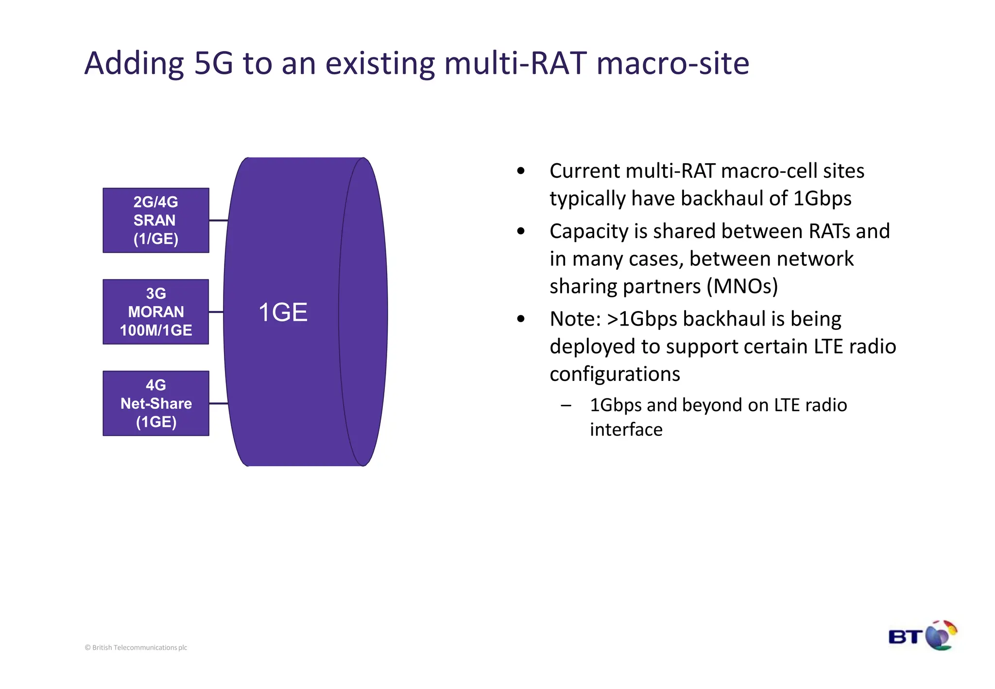
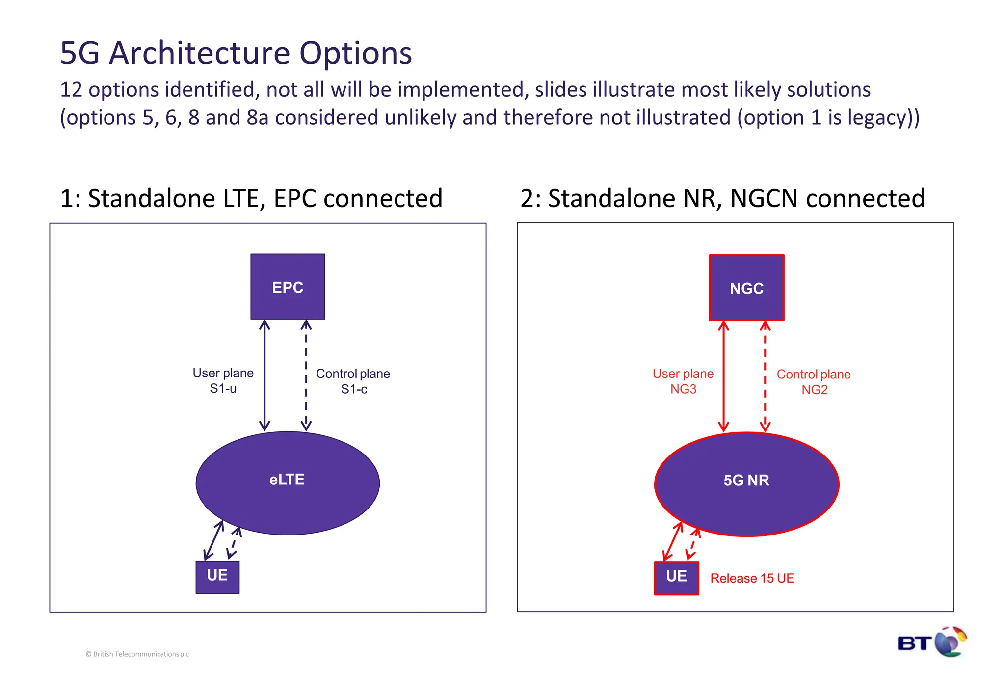
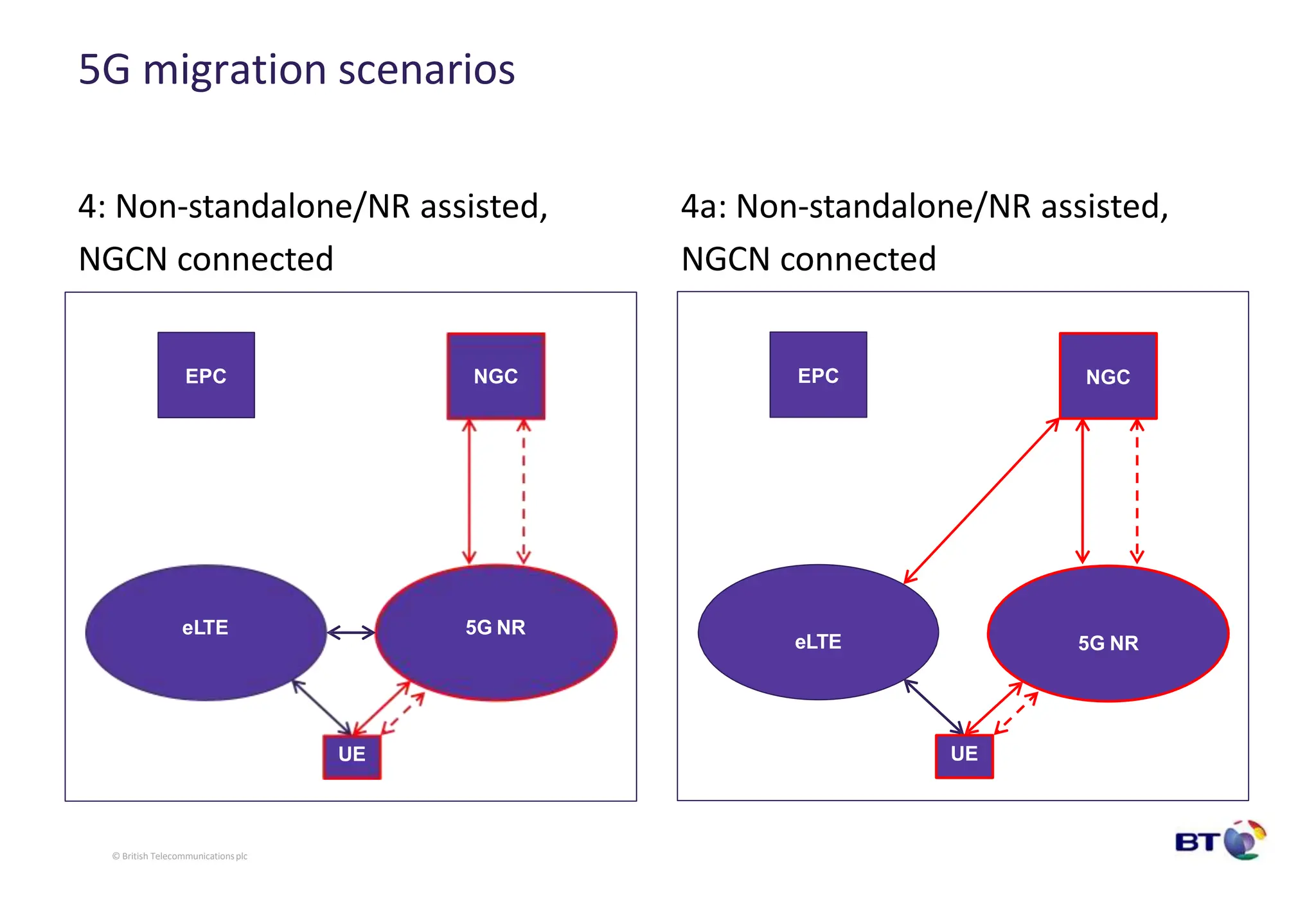
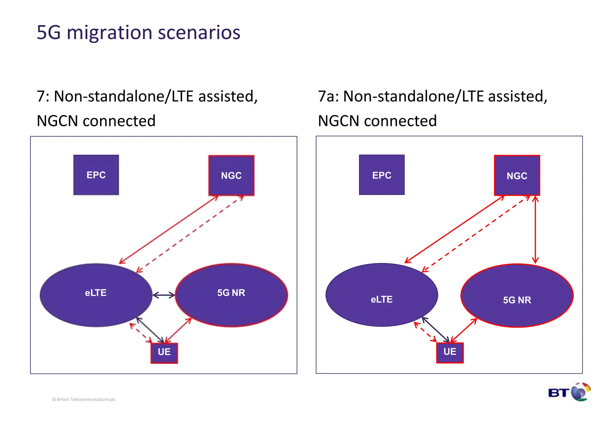
5G Network Architecture and Design
Andy Sutton, Principal Network Architect - Chief Architect’s Office, TSO
25th January 2017
• 5G Network Architecture
– 3GPP logical network architecture
– Functionalblocks
– Reference points (interfaces)
– RAN functional split
• Adding 5G to an existing multi-RAT site
– RAT types and base station
configurations
– Scaling mobile backhaul and/or
introducing NGFI
• 5G Architecture Options
– Standalone and non-standalone modes
of operation
– EPC to NGCN migration scenarios and
inter-working
• Summary
© British Telecommunications plc
Contents
5G Network Architecture
3GPP 5G network architecture
UE RAN UPF DN
AMF SMF PCF
UDM
AF
AUSF
NG1
NG7
NG6
NG5
NG4
NG3
NG2
NG8
NG9 - between UPFs
NG14 - betweenAMFs
NG10
NG11
NG12
© British Telecommunicationsplc
NG13
NG15
NR air i/f
Note: Focus on mobile however Access Network (AN) could be fixed
Functional blocks within 5G network architecture
© British Telecommunicationsplc
1. AUSF = Authentication Server Function
2. UDM = Unified Data Management
3. AMF = Core Access and Mobility Management Function
4. SMF = Session Management Function
5. PCF = Policy Control Function
6. AF = Application Function
7. UE = User Equipment
8. ((R)AN) = (Radio) Access Network
9. UPF = User Plane Function
10. DN = Data Network, e.g. operator services, Internet or 3rd party services
5G interfaces (reference points)
© British Telecommunicationsplc
• NG1:
• NG2:
• NG3:
• NG4:
• NG5:
• NG6:
• NG7:
• NG7r:
• NG8:
• NG9:
• NG10:
• NG11:
Reference point between the UE and the Access and Mobility Management function.
Reference point between the (R)AN and the Access and Mobility Management function.
Reference point between the (R)AN and the User plane function (UPF).
Reference point between the Session Management function (SMF) and the User plane function (UPF).
Reference point between the Policy Function (PCF) and an Application Function (AF).
Reference point between the UP function (UPF) and a Data Network (DN).
Reference point between the Session Management function (SMF) and the Policy Control function (PCF).
Reference point between the vPCF and the hPCF.
Reference point between Unified Data Management and AMF.
Reference point between two Core User plane functions (UPFs).
Reference point between UDM and SMF.
Reference point between Access and Mobility Management function (AMF) and Session Management
function (SMF).
• NG12: Reference point between Access and Mobility Management function (AMF) and Authentication Server
function (AUSF).
• NG13:
• NG14:
• NG15:
Reference point between UDM and Authentication Server function (AUSF).
Reference point between 2 Access and Mobility Management function (AMF).
Reference point between the PCF and the AMF in case of non-roaming scenario, V-PCF and AMF in case of
roaming scenario.
• NG16: Reference point between two SMFs, (in roaming case between V-SMF and the H-SMF).
5G RAN and functional decomposition…
UE RAN UPF DN
NG6
NG3
NR air i/f
DU CU
NGFI
? ?
CU = Centralised Unit
DU = Distributed Unit
NGFI = Next Generation Fronthaul Interface
© British Telecommunicationsplc
RAN functional splits and impact on backhaul
RRC
PDCP
Data
Low-
RLC
High-
MAC
Low-
MAC
High-
PHY
Low-
PHY RF
High-
RLC
RRC
PDCP
Data
Low-
RLC
High-
MAC
Low-
MAC
High-
PHY
Low-
PHY RF
High-
RLC
Option
1
Option
2
Option
3
Option
4
Option
5
Option
6
Option
7
Option
8
End to end
maximum
latency
Capacity
requirement
Higher layer splits Lower layer splits
© British Telecommunicationsplc
Adding 5G to an existing
multi-RAT macro-site
Adding 5G to an existing multi-RAT macro-site
• Current multi-RAT macro-cell sites
typically have backhaul of 1Gbps
• Capacity is shared between RATs and
in many cases, between network
sharing partners (MNOs)
• Note: >1Gbps backhaul is being
deployed to support certain LTE radio
configurations
– 1Gbps and beyond on LTE radio
interface
2G/4G
SRAN
(1/GE)
3G
MORAN
100M/1GE
4G
Net-Share
(1GE)
1GE
© British Telecommunicationsplc
Adding 5G to an existing multi-RAT macro-site
• 5G deployment to macro-cells is very
likely to be <6GHz spectrum bands
• Massive MIMO is a key concept for 5G
– 32/64/128+ antennas
• 5G NR channel bandwidths to be
larger than current LTE channels
• Most spectrum will be unpaired,
therefore phase/time synchronisation
is required for TDD operation
• Assume eMBB is to be the first use
case, the maximum capacity is
required
• Backhaul, or NGFI, will require a
minimum of 10GE local connectivity
with scalable end to end capacity
2G/4G
SRAN
(1/10GE)
3G
MORAN
100M/1GE
4G
Net-Share
(1GE)
5G
gNB
(10GE)
?
© British Telecommunicationsplc
Adding 5G to an existing multi-RAT macro-site
• 5G deployment to macro-cells is likely
to be <6GHz spectrum bands
• Massive MIMO is a key concept for 5G
– 32/64/128+ antennas
• 5G NR channel bandwidths to be
larger than current LTE channels
• Most spectrum will be unpaired,
therefore phase/time synchronisation
is required for TDD operation
• Assume eMBB is to be the first use
case, the maximum capacity is
required
• Backhaul, or NGFI, will require a
minimum of 10GE local connectivity
with scalable end to end capacity
• mm-wave radio backhaul/x-haul will
support 10Gbps+
2G/4G
SRAN
(1/10GE)
3G
MORAN
100M/1GE
4G
Net-Share
(1GE)
5G
gNB
(10GE)
Sub-tended
mm-wave
(10GE+)
?
© British Telecommunicationsplc
5G Architecture Options
12 options identified, not all will be implemented, slides illustrate most likely solutions
(options 5, 6, 8 and 8a considered unlikely and therefore not illustrated (option 1 is legacy))
1: Standalone LTE, EPC connected 2: Standalone NR, NGCN connected
eLTE
EPC
UE
5G NR
NGC
UE
User plane
S1-u
© British Telecommunicationsplc
Control plane
S1-c
User plane
NG3
Control plane
NG2
Release 15 UE
5G migration scenarios
3: Non-standalone/LTE assisted,
EPC connected
3a: Non-standalone/LTE assisted,
EPC connected
eLTE
EPC
5G NR
NGC
UE
eLTE
EPC
5G NR
NGC
UE
© British Telecommunicationsplc
5G migration scenarios
4: Non-standalone/NR assisted,
NGCN connected
4a: Non-standalone/NR assisted,
NGCN connected
eLTE
EPC
5G NR
NGC
UE
EPC
eLTE 5G NR
NGC
UE
© British Telecommunicationsplc
5G migration scenarios
7: Non-standalone/LTE assisted,
NGCN connected
7a: Non-standalone/LTE assisted,
NGCN connected
eLTE
EPC
5G NR
NGC
UE
EPC
eLTE 5G NR
NGC
UE
© British Telecommunicationsplc
Summary
Summary
© British Telecommunicationsplc
• 5G standards are still under development
within 3GPP
• Final technical contributions for the initial 5G
standards are being discussed (Release 15)
• 5G will support enhanced Mobile Broadband
(eMBB), Ultra-Reliable and Low Latency
Communications (URLLC) and massive
Machine Type Communications (mMTC)
• 5G RAN will be different from previous
iteration of C-RAN and D-RAN
• NGFI will likely be implemented for 5G and
eLTE - exact functional splits tbd
• There is significant complexity to manage in
the core network, including inter-working
with and migration to NGCN
• BT is pro-actively developing 5G solutions…
THANK YOU
© British Telecommunicationsplc
Questions?

aaa.pptx

  • 1.
    5G Network Architectureand Design Andy Sutton, Principal Network Architect - Chief Architect’s Office, TSO 25th January 2017
  • 2.
    • 5G NetworkArchitecture – 3GPP logical network architecture – Functionalblocks – Reference points (interfaces) – RAN functional split • Adding 5G to an existing multi-RAT site – RAT types and base station configurations – Scaling mobile backhaul and/or introducing NGFI • 5G Architecture Options – Standalone and non-standalone modes of operation – EPC to NGCN migration scenarios and inter-working • Summary © British Telecommunications plc Contents
  • 3.
  • 4.
    3GPP 5G networkarchitecture UE RAN UPF DN AMF SMF PCF UDM AF AUSF NG1 NG7 NG6 NG5 NG4 NG3 NG2 NG8 NG9 - between UPFs NG14 - betweenAMFs NG10 NG11 NG12 © British Telecommunicationsplc NG13 NG15 NR air i/f Note: Focus on mobile however Access Network (AN) could be fixed
  • 5.
    Functional blocks within5G network architecture © British Telecommunicationsplc 1. AUSF = Authentication Server Function 2. UDM = Unified Data Management 3. AMF = Core Access and Mobility Management Function 4. SMF = Session Management Function 5. PCF = Policy Control Function 6. AF = Application Function 7. UE = User Equipment 8. ((R)AN) = (Radio) Access Network 9. UPF = User Plane Function 10. DN = Data Network, e.g. operator services, Internet or 3rd party services
  • 6.
    5G interfaces (referencepoints) © British Telecommunicationsplc • NG1: • NG2: • NG3: • NG4: • NG5: • NG6: • NG7: • NG7r: • NG8: • NG9: • NG10: • NG11: Reference point between the UE and the Access and Mobility Management function. Reference point between the (R)AN and the Access and Mobility Management function. Reference point between the (R)AN and the User plane function (UPF). Reference point between the Session Management function (SMF) and the User plane function (UPF). Reference point between the Policy Function (PCF) and an Application Function (AF). Reference point between the UP function (UPF) and a Data Network (DN). Reference point between the Session Management function (SMF) and the Policy Control function (PCF). Reference point between the vPCF and the hPCF. Reference point between Unified Data Management and AMF. Reference point between two Core User plane functions (UPFs). Reference point between UDM and SMF. Reference point between Access and Mobility Management function (AMF) and Session Management function (SMF). • NG12: Reference point between Access and Mobility Management function (AMF) and Authentication Server function (AUSF). • NG13: • NG14: • NG15: Reference point between UDM and Authentication Server function (AUSF). Reference point between 2 Access and Mobility Management function (AMF). Reference point between the PCF and the AMF in case of non-roaming scenario, V-PCF and AMF in case of roaming scenario. • NG16: Reference point between two SMFs, (in roaming case between V-SMF and the H-SMF).
  • 7.
    5G RAN andfunctional decomposition… UE RAN UPF DN NG6 NG3 NR air i/f DU CU NGFI ? ? CU = Centralised Unit DU = Distributed Unit NGFI = Next Generation Fronthaul Interface © British Telecommunicationsplc
  • 8.
    RAN functional splitsand impact on backhaul RRC PDCP Data Low- RLC High- MAC Low- MAC High- PHY Low- PHY RF High- RLC RRC PDCP Data Low- RLC High- MAC Low- MAC High- PHY Low- PHY RF High- RLC Option 1 Option 2 Option 3 Option 4 Option 5 Option 6 Option 7 Option 8 End to end maximum latency Capacity requirement Higher layer splits Lower layer splits © British Telecommunicationsplc
  • 9.
    Adding 5G toan existing multi-RAT macro-site
  • 10.
    Adding 5G toan existing multi-RAT macro-site • Current multi-RAT macro-cell sites typically have backhaul of 1Gbps • Capacity is shared between RATs and in many cases, between network sharing partners (MNOs) • Note: >1Gbps backhaul is being deployed to support certain LTE radio configurations – 1Gbps and beyond on LTE radio interface 2G/4G SRAN (1/GE) 3G MORAN 100M/1GE 4G Net-Share (1GE) 1GE © British Telecommunicationsplc
  • 11.
    Adding 5G toan existing multi-RAT macro-site • 5G deployment to macro-cells is very likely to be <6GHz spectrum bands • Massive MIMO is a key concept for 5G – 32/64/128+ antennas • 5G NR channel bandwidths to be larger than current LTE channels • Most spectrum will be unpaired, therefore phase/time synchronisation is required for TDD operation • Assume eMBB is to be the first use case, the maximum capacity is required • Backhaul, or NGFI, will require a minimum of 10GE local connectivity with scalable end to end capacity 2G/4G SRAN (1/10GE) 3G MORAN 100M/1GE 4G Net-Share (1GE) 5G gNB (10GE) ? © British Telecommunicationsplc
  • 12.
    Adding 5G toan existing multi-RAT macro-site • 5G deployment to macro-cells is likely to be <6GHz spectrum bands • Massive MIMO is a key concept for 5G – 32/64/128+ antennas • 5G NR channel bandwidths to be larger than current LTE channels • Most spectrum will be unpaired, therefore phase/time synchronisation is required for TDD operation • Assume eMBB is to be the first use case, the maximum capacity is required • Backhaul, or NGFI, will require a minimum of 10GE local connectivity with scalable end to end capacity • mm-wave radio backhaul/x-haul will support 10Gbps+ 2G/4G SRAN (1/10GE) 3G MORAN 100M/1GE 4G Net-Share (1GE) 5G gNB (10GE) Sub-tended mm-wave (10GE+) ? © British Telecommunicationsplc
  • 13.
  • 14.
    5G Architecture Options 12options identified, not all will be implemented, slides illustrate most likely solutions (options 5, 6, 8 and 8a considered unlikely and therefore not illustrated (option 1 is legacy)) 1: Standalone LTE, EPC connected 2: Standalone NR, NGCN connected eLTE EPC UE 5G NR NGC UE User plane S1-u © British Telecommunicationsplc Control plane S1-c User plane NG3 Control plane NG2 Release 15 UE
  • 15.
    5G migration scenarios 3:Non-standalone/LTE assisted, EPC connected 3a: Non-standalone/LTE assisted, EPC connected eLTE EPC 5G NR NGC UE eLTE EPC 5G NR NGC UE © British Telecommunicationsplc
  • 16.
    5G migration scenarios 4:Non-standalone/NR assisted, NGCN connected 4a: Non-standalone/NR assisted, NGCN connected eLTE EPC 5G NR NGC UE EPC eLTE 5G NR NGC UE © British Telecommunicationsplc
  • 17.
    5G migration scenarios 7:Non-standalone/LTE assisted, NGCN connected 7a: Non-standalone/LTE assisted, NGCN connected eLTE EPC 5G NR NGC UE EPC eLTE 5G NR NGC UE © British Telecommunicationsplc
  • 18.
  • 19.
    Summary © British Telecommunicationsplc •5G standards are still under development within 3GPP • Final technical contributions for the initial 5G standards are being discussed (Release 15) • 5G will support enhanced Mobile Broadband (eMBB), Ultra-Reliable and Low Latency Communications (URLLC) and massive Machine Type Communications (mMTC) • 5G RAN will be different from previous iteration of C-RAN and D-RAN • NGFI will likely be implemented for 5G and eLTE - exact functional splits tbd • There is significant complexity to manage in the core network, including inter-working with and migration to NGCN • BT is pro-actively developing 5G solutions…
  • 20.
    THANK YOU © BritishTelecommunicationsplc Questions?