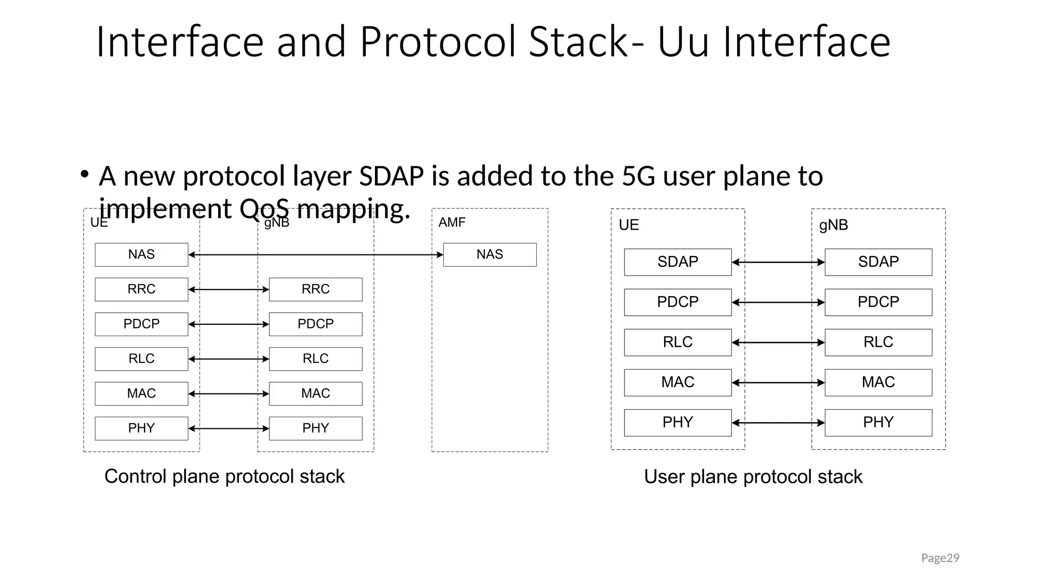
Overview of 5G Wireless Network Principles
• Upon completion of this course, you will be able to:
• Know about 5G network key capability
• 5G Spectrum
• 5G network architecture
• Learn about 5G-related channels and protocol stacks
• 5G typical service flow
Objectives
Page2
Contents
1. 5G Overview
2. 5G Network Architecture and Interface
3. 5G Physical Layer
4. Overview of 5G Basic Signaling Process
Page3
Challenges in 5G Era
Page4
Ultra high
throughput
Ultra-large
connection
Ultra-low latency
eMBB mMTC uRLLC
5G Key Capabilities
Page5
IMT-2020 vs. IMT-Advanced
Comparison of key KPIs
Requirement on key KPIs Of Different
Applications
3x
1ms
1Mdevices/km2
DL 20Gbit/s
UL 10Gbit/s
100X
Peak Rate User Experience
Throughput
(100Mbit/s)
Spectrum
Efficiency
Mobility
(500km/h)
Delay
Connection Density
(1M Equipment/km2)
Region Flow
Capacity (10
Mbit/s/m2
)
Network Power
Efficiency IMT-
Advanced
IMT-2020
uRLLC
mMTC
eMBB
Peak Rate (Gbit/s)
User Experience
Throughput
(Mbit/s)
Spectrum
Efficiency
Mobility
(km/h)
Delay
Connection Density
(Equipment/km2)
Network Power
Efficiency
Region Flow
Capacity
(Mbit/s/m2
)
Page6
New Air Interface Technology
SCMA
F-OFDM
Polar
encoding
Full duplex
Massive MIMO
Mobile
Internet
IoT
Air interface
Adaptive
(Full-duplex mode)
Increase the
throughput.
(Spatial multiplexing)
Increase the throughput.
(Channel code)
Improve reliability.
Reducing power
consumption
(Multiple access)
Increase the number of connections.
Shorten the delay.
(Flexible waveform)
Flexibly coping with different services
5G Network Spectrum
• Adding spectrum is the most direct solution for capacity & transmission speed improvement.
The biggest 5G bandwidth is 1GHz, considering the current spectrum allocation condition,
high frequency spectrum has to be used for 5G communication
Page7
Sub6G
Focus on 3.5GHz
10 50
40
30
20 60 80
70 90
1 5
4
2 6
3
5G expanded spectrum
5G main spectrum
GH
z
Visible
light
Millimeter Wave
Focus on 38/39/60/73GHz
5G Network Spectrum
• 3GPP defines sub-3 GHz, C-band and mmWave as 5G target spectrum.
Page8
Frequency Classification Frequency Range
FR1 410 MHz – 7125 MHz
FR2
24250 MHz – 52600
MHz ( Extended to 71 GHz in
R17 )
5G FR1 Defined in 3GPP Specifications
Page9
NR
Operating
Band
Uplink Downlink
Duplex
Mode
n1 1920-1980MHz 2110-2170MHz FDD
n2 1850-1910MHz 1930-1990MHz FDD
n3 1710-1785MHz 1805-1880MHz FDD
n5 824-849MHz 869-894MHz FDD
n7 2500-2570MHz 2620-2690MHz FDD
n8 880-915MHz 925-960MHz FDD
n20 832-862MHz 791-821MHz FDD
n28 703-748MHz 758-803MHz FDD
n38 2570-2620MHz 2570-2620MHz TDD
n41 2496-2690MHz 2496-2690MHz TDD
n50 1432-1517MHz 1432-1517MHz TDD
n51 1427-1432MHz 1427-1432MHz TDD
n66 1710-1780MHz 2110-2200MHz FDD
n70 1695-1710MHz 1995-2020MHz FDD
n71 663-698MHz 617-652MHz FDD
n74 1427-1470MHz 1475-1518MHz FDD
NR
Operating
Band
Frequency Range
Duplex
Mode
n75 1432-1517MHz SDL
n76 1427-1432MHz SDL
n77 3.3-4.2GHz TDD
n78 3.3-3.8GHz TDD
n79 4.4-5.0GHz TDD
n80 1710-1785MHz SUL
n81 880-915MHz SUL
n82 832-862MHz SUL
n83 703-748MHz SUL
n84 1920-1980MHz SUL
The above table lists some 3GPP-defined
NR sub-6 GHz bands, including
traditional FDD/TDD bands, C band, and
supplementary uplink bands.
5G FR2 Defined in 3GPP Specifications
• The mmWave defined 7 bands for the time being, all are TDD
mode , support the cell bandwidth maximum up to 400MHz
Page11
NR Operating Band Frequency Range Duplex Mode
n257 26500 MHz – 29500 MHz TDD
n258 24250 MHz – 27500 MHz TDD
n259 39500 MHz – 43500 MHz TDD
n260 37000 MHz – 40000 MHz TDD
n261 27500 MHz – 28350 MHz TDD
n262 47200 MHz – 48200 MHz TDD
n263 57000 MHz – 71000 MHz TDD
Global rater is a global frequency grid and is used to calculate the NR ARFCN.
FREF = FREF-Offs + ΔFGlobal (NREF – NREF-Offs)
To accelerate UE access, the Synchronization Raster is defined. The values are 1.2 MHz, 1.44 MHz, and
17.28 MHz.
Frequency range (MHz) ΔFGlobal (kHz) FREF-Offs (MHz) NREF-Offs Range of NREF
0 – 3000 5 0 0 0 – 599999
3000 – 24250 15 3000 600000 600000 – 2016666
Frequency range (MHz) ΔFGlobal (kHz) FREF-Offs [MHz] NREF-Offs Range of NREF
24250 – 100000 60 24250.08 2016667 2016667 – 3279165
NR ARFCN Calculation
Page11
Definition of 5G Cell Bandwidth
• 5G does not use cell bandwidth less than 5 MHz. Large bandwidth is a
typical feature of 5G.
• The bandwidth below 20 MHz is defined to meet the evolution
requirements of existing spectrum.
Page13
Sub-6 GHz mmWave
5 MHz
10 MHz
15 MHz
20 MHz
40 MHz
50 MHz
60 MHz
80 MHz
100 MHz
50 MHz
100 MHz
200 MHz
400 MHz
25 MHz
30 MHz
90 MHz
70 MHz
35 MHz
45 MHz
Contents
1. 5G Overview
2. 5G Network Architecture and Interface
3. 5G Physical Layer
4. Overview of 5G Basic Signaling Process
Page14
Network Architecture- Overview Architecture of 5G
Page15
• Compared with LTE ,the logical function of control plane in 5G core
network is divided into AMF and SMF two functions
A
M
F P
C
F
U
E (R
)A
N U
P
F D
N
N
G
13
N
G
7
N
G
3 N
G
6
N
G
2 N
G
4
N
G
1
A
F
N
G
5
S
M
F
N
G
1
1
N
G
9
A
U
S
F
N
G
8
N
G
12
U
D
M
N
G
1
0
N
G
1
4 N
G
15
Network Architecture- NGC Vs EPC
Page16
EPC NE function Corresponding NGC NF
MME Mobility management AMF
User authentication AUSF
Session management SMF
PDN-GW Session management
User plane data forwarding UPF
SGW User plane data forwarding
PCRF QoS policy and charging rules PCF
HSS User profile database UDM
Network Architecture- 5G Network Structure
• NG-RAN: consists of several
gNodeBs.
• gNB: next Generation NodeB
• NGC: next generation core
(consisting of AMF, UPF, and SMF)
• AMF: access and mobility
management function
• UPF: user plane function
• SMF: session management
function
Page17
gNB
AMF/UPF AMF/UPF
gNB
gNB
NG-C/U
NG-C/U
N
G
-
C
/
U
N
G
-
C
/
U
Xn
X
n
X
n
NG-RAN
NGC
Network Architecture- 5G Network Interfaces
Page18
Interface Name Description
Ng Interface between the gNB and the
CN, similar to the S1 interface of the
LTE
UU Wireless interface between the
terminal and the 5G access network
Xn Interface between gNB and gNB
X2 Interface between 4G and 5G base
station
S1-U User plane interface between the
LTE network and the core network
Network Architecture – NSA Networking
Page19
LTE Anchor , EPC eLTE Anchor , New Core NR Anchor , New Core
Option 3
S1
X2
NR Non-StandAlone
EPC NC
LTE NR
EPC NC
LTE
X2
EPC NC
LTE NR
Option 3a
Option 3X
S1
S1
EPC
NR
EPC
NR
NC
NC
Option 7
Option 7a
eLTE
EPC NC
NR
eLTE
Option 4
S1-U EPC NC
NR
eLTE
Option 4a
eLT
E
S1-U
Ng
Xn
Ng Ng-U
X2-C
NR
Legend
User Plane
Control Plane
phase 1.1 phase 1.2 (new core)
EPC
NR
NC
Option 7X
eLT
E
Ng
Xn
Xn-C
Ng-U 5G NSA gNB would
support 5G SA
without any H/W
changing.
Network Architecture – NSA Networking based on EPC ( Option3 series )
• Option3 Networking Features :
• Common points:
• EPC+NR+eLTE dual-connection networking
• The control plane is provided by the eLTE. NR only
has user plane, which can solve the problem of
continuous coverage at the initial stage.
• Differences: The user plane traffic distribution
solution varies according to the three
architectures.
• Option3: Data is offloaded from the eNodeB.
• Option3a: Data is splited from the EPC.
• Option3x: Data is offloaded from the gNB.
Page20
NSA
Architecture
Features Deployment
Suggestions
Option3 PDCP split on LTE BBU
Limited data peak rate
Need hardware expansion
The user plane is anchored on the
eNodeB side, which reduces the user
plane interruption caused by mobility.
The gNB does not need to connect to
the EPC. Therefore, there is no
requirement for EPC reconstruction.
It is recommended
to be deployed when
the processing
capability on the
LTE side is not
limited.
Option3a Data split from EPC ,static offload
without RAN state awareness
Not recommended.
Option3x PDCP split on NR BBU, no impact on
legacy LTE, dynamic traffic offload
The user plane is anchored in the
gNB, may change frequently.
The EPC needs to interwork with the
gNB.
It is recommended
at the initial stage
and has little impact
on the LTE network.
Network Architecture – NSA EN-DC Downlink Data Split
Page21
• Data traffic from LTE to NR.
• The existing LTE BBU needs to be
reconstructed and expanded.
Option 3
LTE NR
X2
EPC+
PDCP/L
RRC/L
RLC/L
MAC/L
PHY/L
RLC/NR
MAC/NR
PHY/NR
PDCP/NR
LTE BBU NR BBU
EPC+
Option 3x
LTE NR
X2
EPC+
PDCP/L
RRC/L
RLC/L
MAC/L
PHY/L
RLC/NR
MAC/NR
PHY/NR
PDCP/NR
LTE BBU NR BBU
EPC+
• Data traffic from NR to LTE
• The NR coverage is insufficient and multiple
handovers occur.
Network Architecture- NR UL and DL Decoupling
Page22
UL: Low Frequency
Cell radius High Band UL Coverage Low Band UL Coverage
 NR base station uses high frequency band for downlink transmission, for uplink, the frequency
band could be selectively shared with LTE low frequency band depending on UE coverage.
That is an implementation of uplink-downlink decoupling.
DL: High Frequency
DL: High Frequency
UL: High Frequency
1.8G & 3.5G UE uplink frequency
band selection
NR 3.5G
UL
UL
NR 3.5G DL
NR 1.8G
OR
Network Architecture- NR UL and DL Decoupling
• Cloud Air - LTE and NR UL Spectrum
Sharing
• Solution
• LTE and NR share carrier resources
using frequency division, which
prevents resource conflicts.
• LTE and NR determine their
respective available RBs based on
configurations.
• Maximum resource can shared with
NR
• 90% @ 20MHz
• 80% @ 10MHz
Page23
LTE and NR Uplink
Spectrum Sharing
Network Architecture- CU/DU Split
Page24
CU
CU
DU
DU
DU
CPRI/eCPRI
Ethernet
Ethernet
CPRI/eCPRI CPRI/eCPRI
Ethernet
Local DC
(Sites Number~10X)
Regional DC
(Sites Number~>100X)
Antenna & RRU
option1
option2
MCE & APP
MCE & APP
• Benefits: Achieved big area control
processing and resource sharing.
• Disadvantages: The delay is bigger,
which is not suitable for delay-sensitive
services.
• Advantage :Close to the
user, short delay
• Disadvantage :
Resources cannot be
shared in a large scale,
and the equipment room
needs to be reconstructed
to deploy the servers
High efficiency
Better experience
Network Architecture- E2E slicing Architecture
Page25
eMBB Slice
(CN part)
eMBB Slice
(CN part)
mIOT Slice
(CN part)
CriC Slice
(CN part)
CN
domain
RAN
domain
mIOT
RAN-Slice
eMBB
CN-Slice
mIOT
CN-Slice
CriC
CN-Slice
MAC
PHY
Parameters
CriC
RAN-Slice
PDCP
RLC
MAC
PHY PHY
Parameters
eMBB
RAN-Slice
PDCP
RLC RLC
MAC MAC
PHY PHY
Parameters
The RAN side implements slice awareness and multi-slice
sharing of air interface resources.
The core network is customized based on different use case.
Critical
Connectivity
1~5ms latency
eMBB 8K 3D
AR/MR
1~10Gbps
Massive
Connectivity
0.1B
connections
SOC- UP
SOC- CP
SOC- CP
CDN
SOC-UP
SOC- UP
CO Local DC Regional DC
SOC-CP
(PSM)
Voice
High reliability
CU
SOC- UP
SOC- CP
IMS
200Gλ
50Gλ
SDN
Controller
SDN
Controller
DU
DU CU
DU CU
CU
DU
E2E control plane and user plane deployed
according the service dynamically
Interface and Protocol Stack- NG Interface
• The NG interface between the gNodeB and the core network is based
on the IP network. The user plane uses the GTP-U protocol, and the
control plane uses the SCTP protocol (similar to LTE).
Page26
GTP-U
UDP
IP
Data link layer
User plane PDUs
Physical layer
UP protocol stack
SCTP
IP
Data link layer
NG-AP
Physical layer
CP protocol stack
Interface and Protocol Stack- Xn Interface
• The Xn interface between gNodeBs is based on the IP network. The
user plane uses the GTP-U protocol, and the control plane uses the
SCTP protocol (similar to LTE X2 interface).
Page27
GTP-U
UDP
IP
Data link layer
User plane PDUs
Physical layer
Xn-U Protocol Stack
SCTP
IP
Data link layer
Xn-AP
Physical layer
Xn-C Protocol Stack
Interface and Protocol Stack- F1 Interface
• F1 interface is the interface between gNB-CU and gNB-DU
Page28
SCTP
IP
Data link layer
F1AP
Physical layer
Wireless
network layer
Transmission
network layer
Control Plane
User Plane PDU
Wireless
network layer
UDP
IP
Data link layer
Physical layer
Transmi
ssion
network
layer
GTP-U
User Plane
Interface and Protocol Stack- Uu Interface
• A new protocol layer SDAP is added to the 5G user plane to
implement QoS mapping.
Page29
gNB
PHY
UE
PHY
MAC
RLC
MAC
PDCP
PDCP
RLC
SDAP
SDAP
gNB
PHY
UE
PHY
MAC
RLC
MAC
AMF
RLC
NAS NAS
RRC RRC
PDCP PDCP
Control plane protocol stack User plane protocol stack
Uu interface- RRC Layer
• The RRC layer processes all signaling between the UE and the
gNodeB.
Page30
NAS signaling
RRC
PDCP
RLC
MAC
PHY
System messages
Admission control
Security management
Cell reselection
Measurement reporting
Handover and mobility
NAS message transmission
Radio resource management
Uu interface- SDAP Layer
Page31
SDAP
PDCP
RLC
MAC
PHY
The SDAP layer is added to the user
plane.
Implements QoS mapping from 5G QoS
flows to data radio bearers (DRBs).
Marks QoS flow identities (QFIs) in uplink
and downlink data packets.
Uu interface- PDCP Layer
Page32
IP header compression on the user plane
Encryption/Decryption
Integrity check on the control plane
Sorting and replication detection
Routing and replication (in DC scenarios)
Reordering
SDAP
PDCP
RLC
MAC
PHY
Uu interface- RLC Layer
• The RLC layer provides radio link control functions. RLC contains three
transmission modes: TM, UM, and AM. It provides functions such as
error correction, segmentation, and reassembly.
Page33
TM (transparent mode)
UM (unacknowledged mode)
AM (acknowledged mode)
Segmentation and reassembly
Error correction
PDCP
RLC
MAC
PHY
Uu interface- MAC Layer
• The MAC layer provides the following functions: channel mapping and
multiplexing, HARQ, and radio resource allocation.
Page34
Channel mapping and multiplexing
Error correction: HARQ
Radio resource allocation and
scheduling
PDCP
RLC
MAC
PHY
Uu interface- Physical Layer
Page35
Error detection
FEC encryption/decryption
Rate matching
Physical channel mapping
Modulation and demodulation
Frequency synchronization and time
synchronization
Radio measurement
MIMO processing
RF processing
PDCP
RLC
MAC
PHY
Matching
PDCP Scheduling based on QoS
RLC System information broadcast
MAC TM, UM, and AM classification
SDAP IP header compression
RRC Mapping from QoS flows to DRBs
Page36
Matching(Answer)
PDCP Scheduling based on QoS
RLC System information broadcast
MAC TM, UM, and AM classification
SDAP IP header compression
RRC Mapping from QoS flows to DRBs
Page37
Contents
1. 5G Overview
2. 5G Network Architecture and Interface
3. 5G Physical Layer
4. Overview of 5G Basic Signaling Process
Page38
Basic Process of the Physical Layer
Page39
QAM
modulation
MIMO
coding
Antenna 0
output
Resource
mapping
Resource
mapping
Antenna 1
output
Scrambling
Power
control
adjustment
QAM
modulation
Scrambling
Power
control
adjustment
MAC control information
(ACK/CQI/PMI/PC command...)
Interleaving
Interleaving
Code block
concatenatio
n
Code block
concatenatio
n
Rate
Matching
Rate
Matching
Channel
coding
Channel
coding
Code block
Segmentation
Code block
Segmentation
CRC
attachment
User
data
User
data
CRC
attachment
5G Channel Coding- Polar Code and LDPC Code
• The principles for selecting coding algorithms include error correction
performance, delay, and implementation efficiency.
• LDPC encoding
• Low implementation complexity
• Applies to high-speed and big data blocks and has advantages in parallel processing.
• Polar encoding
• When small data blocks are transmitted, the performance is better than that of other
codes.
• Low maturity
• Turbo encoding
• Mature
Page40
LDPC
LDPC+
Turbo
LDPC+
Polar
Polar
Modulation
Page41
Basic modulation principles:
One symbol may represent multiple bits using an
amplitude and a phase, which improves spectral
efficiency by multiple levels. For example, in 16QAM,
one symbol represents four bits.
QPSK
16QAM
64QAM
256QAM
LTE
Uplink
5G
QPSK
16QAM
64QAM
256QAM
Downlink
QPSK
16QAM
64QAM
256QAM
QPSK
16QAM
64QAM
256QAM
F-OFDM
• The F-OFDM technology optimizes channel processing such as filters,
digital pre-distortion (DPD), and radio frequency (RF). Using this
technology, Huawei base stations can effectively improve the spectral
efficiency and peak throughput of the system bandwidth by ensuring
RF protocol specifications such as the adjacent channel leakage power
ratio (ACLR) and blocking.
Page42
LTE: 10% guard band NR: 2%-3% guard band
F-OFDM (+10%)
LTE OFDM
Downlink Beamforming- Beamforming
Page43
• The interference principle is applied to the beamforming. The position of the wave peak and wave
crest is enhanced, and the position overlapping between the wave crest and the wave trough is
weakened.
Beam
Antenna oscillator Antenna oscillator
Overlay enhancement point
Overlaying and weakening points
Carrier wave crest

Beam
Antenna oscillator
Weighted
Antenna oscillator
Weighted
Overlay enhancement point
Overlaying and weakening points
Carrier wave crest

Massive MIMO Significantly Improves Cell Capacity
Page44
 Narrow beamforming
 More beamforming layers
 Higher cell throughput
 Able to cover high floors
using 3D MIMO
 Multi-layer transmission
Massive
MIMO
64T64R
8T8R
2T2R
Adaptive Uplink Waveform
• NR supports Cyclic-Prefix Orthogonal Frequency Division Multiplexing
(CP-OFDM) and DFT-spread OFDM (DFT-S-OFDM).
• CP-OFDM
• Advantage: available discontinuous frequency domain resources, flexible
resource allocation, and large frequency diversity gain
• Disadvantage: relatively high peak-to-average power ratio (PAPR)
• DFT-S-OFDM
• Advantage: low PAPR (approximately close to that of a single carrier) and high
transmit power
• Disadvantage: continuous frequency domain resources required
Page45
Adaptive Uplink Waveform (Cont.)
• According to the radio environment of the UE and the selected
threshold THA, the network side instructs the UE to select a proper CP-
OFDM or DFT-S-OFDM waveform. The UEs between the two
thresholds select different waveforms by using the anti-ping-pong
mechanism. The switching between the two waveforms is
reconfigured by using RRC signaling.
• When the uplink SNR is greater than the threshold THA, the UE selects CP-
OFDM.
• When the uplink SNR is lower than the threshold THB and RANK equals 1, the
UE selects DFT-S-OFDM.
• If the SNR is between THA and THB, the current waveform remains unchanged.
Page46
The UE selects
DFT-S-OFDM.
Waveform remains
unchanged.
The UE selects
CP-OFDM.
Uplink SNR
Resource Mapping- Overview of Physical Resources
Page47
Radio frame
OFDM symbol
Physical
channels and
signals
Basic timing
unit: Ts
Slot
Subframe
Physical resources
Time Domain Resources- Frame, Subframe, Slot, and Symbol
Page48
• The general structure of the time domain on the air interface meets the requirements of
data transmission and in-band control for different RATs.
Radio frame
Subframe Subframe Subframe
…
Slot Slot Slot
…
Period for sending part of control
information, and unit for allocating
uplink and downlink subframes
Symbol Symbol Symbol
…
Basic data transmission period
Basic unit of modulation
Minimum unit of data scheduling
and synchronization
Frame Structure
• 1 radio frame = 10 ms
• 1 radio frame = 10 subframes
• 1 subframe = 1 ms
Page49
#0 #1 #2 #3 #9
#8
One radiofram
e, Tf=10m
s
One subframe, Tsf=1m
s
Flexible Air Interface Configuration-
Numerologies
Page50
6 7 8 9 10
5
6 7 8 9
0 1 2 3 4 12 13
…
11
0 1 2 3 4 5 10 11 12 13
2 3 4 5
SCS=15k
(TTI=1ms)
SCS=30k
(TTI=0.5ms)
SCS=60K
(TTI=0.25ms)
TTI(Slot)=0.5ms TTI
TTI(Slot)=0.25ms TTI=0.25ms …
…
0. 5m
s
0. 5m
s
6 7 … 13
TTI(Slot)= 14 symbols = 1ms
0 1
µ SCS Cyclic prefix
0 15kHz Normal
1 30kHz Normal
2 60kHz Normal, Extended
3 120kHz Normal
4 240kHz Normal
Numerology: The flexible frame format refers to flexible
configuration of a group of parameters such as SCS (SubCarrier
Spacing) in the NR, symbol length and a CP length
corresponding to the SCS.
The parameter μ is used as the index of the related configuration.
Multi Numerologies
• NR supports multiple numerologies (different
subcarrier bandwidths and CPs).
Page51
Subcarrier
Configuration
Subcarrie
r
Bandwidt
h
CP
Number of
Symbols per
Slot
Number of
Slots per
Frame
Number of
Slots per
Subframe
CP
0 15 Normal 14 10 1
1 30 Normal 14 20 2
2 60 Normal 14 40 4
3 120 Normal 14 80 8
4 240 Normal 14 160 16
5 480 Normal 14 320 32
2 60
extende
d
12 40 4
t
f
eMBB
mMTC
URLLC
Broadcast
Configurable
TTI
Configurable
subcarrier spacing
1 slot = 14 symbols
1 subframe = 4 slots
1 frame = 10 subframes = 40 slots
1
subcarrier
=
60KHz
2


 KHz
15
2 
 slot
symb
N 
frame,
slot
N 
subframe,
slot
N
Relationship Between the Subcarrier Bandwidth
and The Maximum Bandwidth of the Cell
• According to the limitation of maximum RB numbers described by
3GPP:
• In FR1, only the subcarrier spacing is greater than 15K, the cell bandwidth can
be configured with 100M.
• In FR2, only the subcarrier spacing is greater than 60K, the cell bandwidth can
be configured with 400M.
Page52
SCS
(kHz)
5MH
z
10M
Hz
15
MHz
20
MHz
25
MHz
30
MHz
35
MHz
40
MHz
45
MHz
50
MHz
60
MHz
70
MHz
80
MHz
100
MHz
NRB NRB NRB NRB NRB NRB NRB NRB NRB NRB NRB NRB NRB NRB
15 25 52 79 106 133 160 188 216 242 270 N/A N/A N/A N/A
30 11 24 38 51 65 78 92 106 119 133 162 189 217 273
60 N/A 11 18 24 31 38 44 51 58 65 79 93 107 135
SCS
(kHz)
50MHz 100MHz 200MHz 400 MHz
NRB NRB NRB NRB
60 66 132 264 N/A
120 32 66 132 264
Self-Contained Frame Structure
• Self-contained slots are classified into DL-dominant slots and UL-
dominant slots:
• The uplink part of DL-dominant slots can be used for the transmission of
uplink control information and SRSs.
• The downlink part of UL-dominant slots can be used for the transmission of
downlink control information.
Page53
DL
Type 1: DL-only slot
UL
Type 2: UL-only slot
DL UL
Uplink Controlor SRS Downlink Control
DL-dominant UL-dominant
Type 3: Mixed DL and UL slot
Basic Frequency Domain Resource Unit
• Resource element (RE)
• For each antenna port p, a unit
corresponding to a subcarrier on an
OFDM symbol is called an RE. (The
subcarrier spacing corresponding to μ
is 2μ
x15 kHz.)
• Resource block (RB)
• 12 consecutive REs in the frequency
domain are one RB.
• CCE : Control Channel Element
• 1CCE = 6REG = 6PRB
Page54
OFDM symbols
One subframe
subcarriers
subcarriers
Resource element
- in resource grid
- in resource block
Resource block
Channel Management- Logical channels
• Logical channels are available between the MAC layer and the RLC layer.
Each logical channel type is defined according to the type of the data to be
transmitted. Generally, logical channels are classified into control channels
and traffic channels.
• Control channels include:
• Broadcast control channel (BCCH)
• Paging control channel (PCCH)
• Common control channel (CCCH)
• Dedicated control channel (DCCH)
• Traffic channels include:
• Dedicated traffic channel (DTCH)
Page55
Channel Management- Transport channels
• Transport channels are available between the MAC layer and the PHY
layer. Each transport channel type is defined according to the transmission
data type and the data transmission method on the air interface.
• Downlink transport channels are classified into:
• Broadcast channel (BCH)
• Downlink shared channel (DL-SCH)
• Paging channel (PCH)
• Uplink transport channels are classified into:
• Uplink shared channel (UL-SCH)
• Random access channel (RACH)
Page56
Channel Management- Physical channels
• Physical channels perform coding, modulation, multi-antenna processing, and
mapping of signals onto appropriate physical time-frequency resources. An
upper-layer transport channel can be mapped to one or more physical channels.
• Downlink physical channels include:
• Physical broadcast channel (PBCH)
• Physical downlink control channel (PDCCH)
• Physical downlink shared channel (PDSCH)
• Uplink physical channels include:
• Physical uplink control channel (PUCCH)
• Physical uplink shared channel (PUSCH)
• Physical random access channel (PRACH)
Page57
Channel Management- Downlink Physical Channels
Page58
PBCH
Modulation scheme: QPSK
The PBCH broadcasts system information MIB.
PDSCH
Modulation schemes:
QPSK, 16QAM, 64QAM,
256QAM
The PDSCH carries
dedicated user data.
PDCCH
Modulation scheme: QPSK
The PDCCH carries
scheduling, transmission
format, and HARQ
information.
Downlink
physical
channels
Channel Management- Downlink Physical Signals
Page59
DMRS for the PDSCH
Phase-tracking reference signal
(PT-RS), used in high-band
scenarios
Channel state information-reference signal (CSI-RS)
Downlink
physical
signals
Demodulation reference
signal (DMRS) for the PDCCH
DMRS for the PBCH
Downlink Physical Channel Processing
Physical
Channel
Channel
Coding
Modulation Scheme Number of Layers Waveform
PDSCH LDPC QPSK, 16QAM, 64QAM, 256QAM 1-8 layers CP-OFDM
PBCH Polar QPSK 1 CP-OFDM
PDCCH Polar QPSK 1 CP-OFDM
Scrambling
Scrambling
Modulation
mapper
Modulation
mapper
Layer
mapper
Antenna port
mapper
Resource element
mapper
Resource element
mapper
OFDM signal
generation
OFDM signal
generation
Codeword Layers Antenna ports
These procedures do not apply to the PDCCH and PBCH.
…
Channel Management- Uplink Physical Channels
Page61
PUSCH
Modulation scheme: QPSK, 16QAM, 64QAM, 256QAM
The PUSCH carries dedicated user data.
PRACH
Modulation scheme: QPSK
The PRACH carries random access preamble.
PUCCH
Modulation scheme: QPSK, π/2-BPSK
The PUCCH carries ACK/NACK,
scheduling request (SR), and CSI-Report
(PMI, CQI, and so on).
Uplink
physical
channels
Channel Management- Uplink Physical Signals
Page62
SRS
SRSs are provided to the base station as
the input for downlink MIMO precoding.
Uplink
physical
signals
DMRS for PUSCH DMRS for PUCCH
PT-RS
Channel Management- Downlink channel
mapping
Page63
MAC
PHY
c
BCH PCH
PBCH PDSCH PDCCH
Downlink transport channels
Downlink physical channels
DL-SCH
c
CCCH DCCH
Downlink logical channels
c c c
DTCH
RLC
c
c
PCCH
BCCH
Channel Management- Uplink channel
mapping
Page64
c
CCCH DCCH
UL-SCH RACH
Uplink logical channels
Uplink transport channels
c c c
DTCH
PUSCH PRACH PUCCH
Uplink physical channels
RLC
MAC
PHY
Contents
1. 5G Overview
2. 5G Network Architecture and Interface
3. 5G Physical Layer
4. Overview of 5G Basic Signaling Process
Page65
5G Networking Mode
• Phase1.1 launches the 5G non-standalone networking architecture (NSA, NR+EPC) and uses
the MSA technology to implement collaboration between the two modes. Phase1.2
launched the 5G independent network architecture (SA, NR+NGC).
Page66
NSA SA
LTE
S1
EPC
Control plane
User plane
5G NR
S1
EPC
LTE 5G NR
NG-C
NG CORE
NG-U
Control plane
User plane
Basic Signaling Procedures in SA Networking
Page67
Overview of System Message Broadcast
• NR synchronization and system message broadcasting include: PSS/SSS,
PBCH, RMSI, and OSI
• The PSS/SSS is used by the UE to synchronize the downlink clock and obtain the cell
ID of the cell.
• The PBCH (MIB) is used by the UE to obtain the basic information about the access
network. It is mainly used to notify the UE where to receive the RMSI message.
• The RMSI (SIB1) is used to broadcast the initial BWP information, the UL and DL ratio
of the TDD cell, and the necessary information for other UEs to access the network.
• Other System Information (OSI) is used to broadcast other cell information.
(Currently, this part is not used in NSA networking.)
• To support massive MIMO, all broadcast channels and signals support beam
scanning.
Page68
Broadcast channel beam scanning
• A broadcast beam can be designed for a maximum of N directional
beams. The broadcast beam coverage of the cell is completed by
sending different beams at different moments. By scanning beams,
the UE obtains an optimal beam, and completes synchronization and
system message demodulation.
Page69
#0
#1
#2
#N-3
#N-2
#N-1
Time
.
.
.
Decodes SSB blocks.
Synchronization
Obtain MIB information.
Obtaining the SSB
Index:2
System Information Broadcast
• System information broadcast is the first step for a UE to obtain the
basic network service information. In this procedure, the gNodeB
transmits system information and the UE obtains system information.
Page70
Category Information
Type
Content
MSI MIB System frame number (SFN) and information used to capture SIB1
SIB1 Operator information of the cell, initial bandwidth part (BWP) information, and scheduling
information of other SIBs
OSI SIB2 Common information required for intra-frequency cell reselection, inter-frequency cell reselection,
and inter-RAT cell reselection
SIB3 Intra-frequency cell reselection parameters and intra-frequency cell blacklist
SIB4 Non-serving frequency reselection parameters, inter-frequency cell reselection parameters, and
inter-frequency cell blacklist
SIB5 Inter-RAT frequency reselection parameters, inter-RAT cell reselection parameters, and inter-RAT
cell blacklist
SIB9 Coordinated Universal Time (UTC), Global Positioning System (GPS) time, and local time
System Information Broadcast
Page71
Random Access
Page72
Triggering Scenario Scenario Description Mechanism
Initial RRC connection
setup
When a UE needs to change from the RRC_IDLE state to
RRC_CONNECTED state, the UE initiates RA to establish an
RRC connection.
Contention-based RA
RRC connection
reestablishment
After detecting a radio link failure, a UE initiates RA to reestablish
an RRC connection.
Contention-based RA
Handover During a handover, a UE initiates RA in the target cell. Non-contention-based RA is
the first choice
Downlink data arrival When a gNodeB needs to send downlink data to an
RRC_CONNECTED UE in an uplink out-of-synchronization state,
the gNodeB instructs the UE to initiate RA.
Contention-based RA
Uplink data transmission When an RRC_CONNECTED UE in an uplink out-of-
synchronization state needs to send uplink data to a gNodeB, the
UE initiates RA.
Contention-based RA
Transition from the
RRC_INACTIVE state to
RRC_CONNECTED state
When a UE switches from the RRC_INACTIVE state to
RRC_CONNECTED state, the UE initiates RA.
Contention-based RA
Random Access
Page73
Contention-based RA Non-contention-based RA
RRC Connection Setup
Page74
Context Setup
Page75
Context Setup
Page76
PDU Session Setup
• Establishing DRBs and NG-U transmission tunnels for QoS flows for
one or more PDU sessions
Page77
Basic Signaling Procedures in NSA
Networking
• In NSA networking, signaling
plane data is carried on the
LTE side. Therefore, the basic
access procedures are the
same as those on the LTE
side. In addition, the NR B1
measurement, NG-RAN radio
bearer management
(including the SgNB addition
procedure), and RA to the
gNodeB are added.
Page78
Initial SgNB Addition Procedure
Page79
SgNB Change
• SgNB change is a process in which the PSCELL of a UE is transferred from a cell on the NR side to another cell in the NSA
scenario,
• In the NSA scenario, the measurement event of the NR is delivered on the LTE side. The NR has a measurement control
module. The measurement control information of the NR measurement control module is transmitted to the LTE through
the X2 interface. The LTE delivers the measurement control information to the UE. The measurement information of the
UE is reported to the LTE, and the LTE sends the measurement report information to the NR through the X2 interface.
Page80
LTE 5G 2
UP
C
P
+
U
P
•Good Coverage
•Rare Spectrum
•Rich Spectrum
•Poor Coverage
5G 1
Inter-SgNB Handover Procedure
Page81
Acronyms and Abbreviations
• EN-DC : E-UTRAN-NR Dual Connectivity
• MeNB : Master eNodeB
• NR : New Radio
• NSA : Non-Standalone
• PCell : Primary Cell
• PSCell : Primary SCell
• SA : Standalone
• SgNB : Secondary gNodeB
Page82
Summary
• 5G overview
• 5G network architecture and the main interface
• Uu interface and the protocol stack
• 5G physical layer and the channels
• 5G typical flows
Page83
Overview &  Wireless Network Principles.pptx

Overview & Wireless Network Principles.pptx

  • 1.
    Overview of 5GWireless Network Principles
  • 2.
    • Upon completionof this course, you will be able to: • Know about 5G network key capability • 5G Spectrum • 5G network architecture • Learn about 5G-related channels and protocol stacks • 5G typical service flow Objectives Page2
  • 3.
    Contents 1. 5G Overview 2.5G Network Architecture and Interface 3. 5G Physical Layer 4. Overview of 5G Basic Signaling Process Page3
  • 4.
    Challenges in 5GEra Page4 Ultra high throughput Ultra-large connection Ultra-low latency eMBB mMTC uRLLC
  • 5.
    5G Key Capabilities Page5 IMT-2020vs. IMT-Advanced Comparison of key KPIs Requirement on key KPIs Of Different Applications 3x 1ms 1Mdevices/km2 DL 20Gbit/s UL 10Gbit/s 100X Peak Rate User Experience Throughput (100Mbit/s) Spectrum Efficiency Mobility (500km/h) Delay Connection Density (1M Equipment/km2) Region Flow Capacity (10 Mbit/s/m2 ) Network Power Efficiency IMT- Advanced IMT-2020 uRLLC mMTC eMBB Peak Rate (Gbit/s) User Experience Throughput (Mbit/s) Spectrum Efficiency Mobility (km/h) Delay Connection Density (Equipment/km2) Network Power Efficiency Region Flow Capacity (Mbit/s/m2 )
  • 6.
    Page6 New Air InterfaceTechnology SCMA F-OFDM Polar encoding Full duplex Massive MIMO Mobile Internet IoT Air interface Adaptive (Full-duplex mode) Increase the throughput. (Spatial multiplexing) Increase the throughput. (Channel code) Improve reliability. Reducing power consumption (Multiple access) Increase the number of connections. Shorten the delay. (Flexible waveform) Flexibly coping with different services
  • 7.
    5G Network Spectrum •Adding spectrum is the most direct solution for capacity & transmission speed improvement. The biggest 5G bandwidth is 1GHz, considering the current spectrum allocation condition, high frequency spectrum has to be used for 5G communication Page7 Sub6G Focus on 3.5GHz 10 50 40 30 20 60 80 70 90 1 5 4 2 6 3 5G expanded spectrum 5G main spectrum GH z Visible light Millimeter Wave Focus on 38/39/60/73GHz
  • 8.
    5G Network Spectrum •3GPP defines sub-3 GHz, C-band and mmWave as 5G target spectrum. Page8 Frequency Classification Frequency Range FR1 410 MHz – 7125 MHz FR2 24250 MHz – 52600 MHz ( Extended to 71 GHz in R17 )
  • 9.
    5G FR1 Definedin 3GPP Specifications Page9 NR Operating Band Uplink Downlink Duplex Mode n1 1920-1980MHz 2110-2170MHz FDD n2 1850-1910MHz 1930-1990MHz FDD n3 1710-1785MHz 1805-1880MHz FDD n5 824-849MHz 869-894MHz FDD n7 2500-2570MHz 2620-2690MHz FDD n8 880-915MHz 925-960MHz FDD n20 832-862MHz 791-821MHz FDD n28 703-748MHz 758-803MHz FDD n38 2570-2620MHz 2570-2620MHz TDD n41 2496-2690MHz 2496-2690MHz TDD n50 1432-1517MHz 1432-1517MHz TDD n51 1427-1432MHz 1427-1432MHz TDD n66 1710-1780MHz 2110-2200MHz FDD n70 1695-1710MHz 1995-2020MHz FDD n71 663-698MHz 617-652MHz FDD n74 1427-1470MHz 1475-1518MHz FDD NR Operating Band Frequency Range Duplex Mode n75 1432-1517MHz SDL n76 1427-1432MHz SDL n77 3.3-4.2GHz TDD n78 3.3-3.8GHz TDD n79 4.4-5.0GHz TDD n80 1710-1785MHz SUL n81 880-915MHz SUL n82 832-862MHz SUL n83 703-748MHz SUL n84 1920-1980MHz SUL The above table lists some 3GPP-defined NR sub-6 GHz bands, including traditional FDD/TDD bands, C band, and supplementary uplink bands.
  • 10.
    5G FR2 Definedin 3GPP Specifications • The mmWave defined 7 bands for the time being, all are TDD mode , support the cell bandwidth maximum up to 400MHz Page11 NR Operating Band Frequency Range Duplex Mode n257 26500 MHz – 29500 MHz TDD n258 24250 MHz – 27500 MHz TDD n259 39500 MHz – 43500 MHz TDD n260 37000 MHz – 40000 MHz TDD n261 27500 MHz – 28350 MHz TDD n262 47200 MHz – 48200 MHz TDD n263 57000 MHz – 71000 MHz TDD
  • 11.
    Global rater isa global frequency grid and is used to calculate the NR ARFCN. FREF = FREF-Offs + ΔFGlobal (NREF – NREF-Offs) To accelerate UE access, the Synchronization Raster is defined. The values are 1.2 MHz, 1.44 MHz, and 17.28 MHz. Frequency range (MHz) ΔFGlobal (kHz) FREF-Offs (MHz) NREF-Offs Range of NREF 0 – 3000 5 0 0 0 – 599999 3000 – 24250 15 3000 600000 600000 – 2016666 Frequency range (MHz) ΔFGlobal (kHz) FREF-Offs [MHz] NREF-Offs Range of NREF 24250 – 100000 60 24250.08 2016667 2016667 – 3279165 NR ARFCN Calculation Page11
  • 12.
    Definition of 5GCell Bandwidth • 5G does not use cell bandwidth less than 5 MHz. Large bandwidth is a typical feature of 5G. • The bandwidth below 20 MHz is defined to meet the evolution requirements of existing spectrum. Page13 Sub-6 GHz mmWave 5 MHz 10 MHz 15 MHz 20 MHz 40 MHz 50 MHz 60 MHz 80 MHz 100 MHz 50 MHz 100 MHz 200 MHz 400 MHz 25 MHz 30 MHz 90 MHz 70 MHz 35 MHz 45 MHz
  • 13.
    Contents 1. 5G Overview 2.5G Network Architecture and Interface 3. 5G Physical Layer 4. Overview of 5G Basic Signaling Process Page14
  • 14.
    Network Architecture- OverviewArchitecture of 5G Page15 • Compared with LTE ,the logical function of control plane in 5G core network is divided into AMF and SMF two functions A M F P C F U E (R )A N U P F D N N G 13 N G 7 N G 3 N G 6 N G 2 N G 4 N G 1 A F N G 5 S M F N G 1 1 N G 9 A U S F N G 8 N G 12 U D M N G 1 0 N G 1 4 N G 15
  • 15.
    Network Architecture- NGCVs EPC Page16 EPC NE function Corresponding NGC NF MME Mobility management AMF User authentication AUSF Session management SMF PDN-GW Session management User plane data forwarding UPF SGW User plane data forwarding PCRF QoS policy and charging rules PCF HSS User profile database UDM
  • 16.
    Network Architecture- 5GNetwork Structure • NG-RAN: consists of several gNodeBs. • gNB: next Generation NodeB • NGC: next generation core (consisting of AMF, UPF, and SMF) • AMF: access and mobility management function • UPF: user plane function • SMF: session management function Page17 gNB AMF/UPF AMF/UPF gNB gNB NG-C/U NG-C/U N G - C / U N G - C / U Xn X n X n NG-RAN NGC
  • 17.
    Network Architecture- 5GNetwork Interfaces Page18 Interface Name Description Ng Interface between the gNB and the CN, similar to the S1 interface of the LTE UU Wireless interface between the terminal and the 5G access network Xn Interface between gNB and gNB X2 Interface between 4G and 5G base station S1-U User plane interface between the LTE network and the core network
  • 18.
    Network Architecture –NSA Networking Page19 LTE Anchor , EPC eLTE Anchor , New Core NR Anchor , New Core Option 3 S1 X2 NR Non-StandAlone EPC NC LTE NR EPC NC LTE X2 EPC NC LTE NR Option 3a Option 3X S1 S1 EPC NR EPC NR NC NC Option 7 Option 7a eLTE EPC NC NR eLTE Option 4 S1-U EPC NC NR eLTE Option 4a eLT E S1-U Ng Xn Ng Ng-U X2-C NR Legend User Plane Control Plane phase 1.1 phase 1.2 (new core) EPC NR NC Option 7X eLT E Ng Xn Xn-C Ng-U 5G NSA gNB would support 5G SA without any H/W changing.
  • 19.
    Network Architecture –NSA Networking based on EPC ( Option3 series ) • Option3 Networking Features : • Common points: • EPC+NR+eLTE dual-connection networking • The control plane is provided by the eLTE. NR only has user plane, which can solve the problem of continuous coverage at the initial stage. • Differences: The user plane traffic distribution solution varies according to the three architectures. • Option3: Data is offloaded from the eNodeB. • Option3a: Data is splited from the EPC. • Option3x: Data is offloaded from the gNB. Page20 NSA Architecture Features Deployment Suggestions Option3 PDCP split on LTE BBU Limited data peak rate Need hardware expansion The user plane is anchored on the eNodeB side, which reduces the user plane interruption caused by mobility. The gNB does not need to connect to the EPC. Therefore, there is no requirement for EPC reconstruction. It is recommended to be deployed when the processing capability on the LTE side is not limited. Option3a Data split from EPC ,static offload without RAN state awareness Not recommended. Option3x PDCP split on NR BBU, no impact on legacy LTE, dynamic traffic offload The user plane is anchored in the gNB, may change frequently. The EPC needs to interwork with the gNB. It is recommended at the initial stage and has little impact on the LTE network.
  • 20.
    Network Architecture –NSA EN-DC Downlink Data Split Page21 • Data traffic from LTE to NR. • The existing LTE BBU needs to be reconstructed and expanded. Option 3 LTE NR X2 EPC+ PDCP/L RRC/L RLC/L MAC/L PHY/L RLC/NR MAC/NR PHY/NR PDCP/NR LTE BBU NR BBU EPC+ Option 3x LTE NR X2 EPC+ PDCP/L RRC/L RLC/L MAC/L PHY/L RLC/NR MAC/NR PHY/NR PDCP/NR LTE BBU NR BBU EPC+ • Data traffic from NR to LTE • The NR coverage is insufficient and multiple handovers occur.
  • 21.
    Network Architecture- NRUL and DL Decoupling Page22 UL: Low Frequency Cell radius High Band UL Coverage Low Band UL Coverage  NR base station uses high frequency band for downlink transmission, for uplink, the frequency band could be selectively shared with LTE low frequency band depending on UE coverage. That is an implementation of uplink-downlink decoupling. DL: High Frequency DL: High Frequency UL: High Frequency 1.8G & 3.5G UE uplink frequency band selection NR 3.5G UL UL NR 3.5G DL NR 1.8G OR
  • 22.
    Network Architecture- NRUL and DL Decoupling • Cloud Air - LTE and NR UL Spectrum Sharing • Solution • LTE and NR share carrier resources using frequency division, which prevents resource conflicts. • LTE and NR determine their respective available RBs based on configurations. • Maximum resource can shared with NR • 90% @ 20MHz • 80% @ 10MHz Page23 LTE and NR Uplink Spectrum Sharing
  • 23.
    Network Architecture- CU/DUSplit Page24 CU CU DU DU DU CPRI/eCPRI Ethernet Ethernet CPRI/eCPRI CPRI/eCPRI Ethernet Local DC (Sites Number~10X) Regional DC (Sites Number~>100X) Antenna & RRU option1 option2 MCE & APP MCE & APP • Benefits: Achieved big area control processing and resource sharing. • Disadvantages: The delay is bigger, which is not suitable for delay-sensitive services. • Advantage :Close to the user, short delay • Disadvantage : Resources cannot be shared in a large scale, and the equipment room needs to be reconstructed to deploy the servers High efficiency Better experience
  • 24.
    Network Architecture- E2Eslicing Architecture Page25 eMBB Slice (CN part) eMBB Slice (CN part) mIOT Slice (CN part) CriC Slice (CN part) CN domain RAN domain mIOT RAN-Slice eMBB CN-Slice mIOT CN-Slice CriC CN-Slice MAC PHY Parameters CriC RAN-Slice PDCP RLC MAC PHY PHY Parameters eMBB RAN-Slice PDCP RLC RLC MAC MAC PHY PHY Parameters The RAN side implements slice awareness and multi-slice sharing of air interface resources. The core network is customized based on different use case. Critical Connectivity 1~5ms latency eMBB 8K 3D AR/MR 1~10Gbps Massive Connectivity 0.1B connections SOC- UP SOC- CP SOC- CP CDN SOC-UP SOC- UP CO Local DC Regional DC SOC-CP (PSM) Voice High reliability CU SOC- UP SOC- CP IMS 200Gλ 50Gλ SDN Controller SDN Controller DU DU CU DU CU CU DU E2E control plane and user plane deployed according the service dynamically
  • 25.
    Interface and ProtocolStack- NG Interface • The NG interface between the gNodeB and the core network is based on the IP network. The user plane uses the GTP-U protocol, and the control plane uses the SCTP protocol (similar to LTE). Page26 GTP-U UDP IP Data link layer User plane PDUs Physical layer UP protocol stack SCTP IP Data link layer NG-AP Physical layer CP protocol stack
  • 26.
    Interface and ProtocolStack- Xn Interface • The Xn interface between gNodeBs is based on the IP network. The user plane uses the GTP-U protocol, and the control plane uses the SCTP protocol (similar to LTE X2 interface). Page27 GTP-U UDP IP Data link layer User plane PDUs Physical layer Xn-U Protocol Stack SCTP IP Data link layer Xn-AP Physical layer Xn-C Protocol Stack
  • 27.
    Interface and ProtocolStack- F1 Interface • F1 interface is the interface between gNB-CU and gNB-DU Page28 SCTP IP Data link layer F1AP Physical layer Wireless network layer Transmission network layer Control Plane User Plane PDU Wireless network layer UDP IP Data link layer Physical layer Transmi ssion network layer GTP-U User Plane
  • 28.
    Interface and ProtocolStack- Uu Interface • A new protocol layer SDAP is added to the 5G user plane to implement QoS mapping. Page29 gNB PHY UE PHY MAC RLC MAC PDCP PDCP RLC SDAP SDAP gNB PHY UE PHY MAC RLC MAC AMF RLC NAS NAS RRC RRC PDCP PDCP Control plane protocol stack User plane protocol stack
  • 29.
    Uu interface- RRCLayer • The RRC layer processes all signaling between the UE and the gNodeB. Page30 NAS signaling RRC PDCP RLC MAC PHY System messages Admission control Security management Cell reselection Measurement reporting Handover and mobility NAS message transmission Radio resource management
  • 30.
    Uu interface- SDAPLayer Page31 SDAP PDCP RLC MAC PHY The SDAP layer is added to the user plane. Implements QoS mapping from 5G QoS flows to data radio bearers (DRBs). Marks QoS flow identities (QFIs) in uplink and downlink data packets.
  • 31.
    Uu interface- PDCPLayer Page32 IP header compression on the user plane Encryption/Decryption Integrity check on the control plane Sorting and replication detection Routing and replication (in DC scenarios) Reordering SDAP PDCP RLC MAC PHY
  • 32.
    Uu interface- RLCLayer • The RLC layer provides radio link control functions. RLC contains three transmission modes: TM, UM, and AM. It provides functions such as error correction, segmentation, and reassembly. Page33 TM (transparent mode) UM (unacknowledged mode) AM (acknowledged mode) Segmentation and reassembly Error correction PDCP RLC MAC PHY
  • 33.
    Uu interface- MACLayer • The MAC layer provides the following functions: channel mapping and multiplexing, HARQ, and radio resource allocation. Page34 Channel mapping and multiplexing Error correction: HARQ Radio resource allocation and scheduling PDCP RLC MAC PHY
  • 34.
    Uu interface- PhysicalLayer Page35 Error detection FEC encryption/decryption Rate matching Physical channel mapping Modulation and demodulation Frequency synchronization and time synchronization Radio measurement MIMO processing RF processing PDCP RLC MAC PHY
  • 35.
    Matching PDCP Scheduling basedon QoS RLC System information broadcast MAC TM, UM, and AM classification SDAP IP header compression RRC Mapping from QoS flows to DRBs Page36
  • 36.
    Matching(Answer) PDCP Scheduling basedon QoS RLC System information broadcast MAC TM, UM, and AM classification SDAP IP header compression RRC Mapping from QoS flows to DRBs Page37
  • 37.
    Contents 1. 5G Overview 2.5G Network Architecture and Interface 3. 5G Physical Layer 4. Overview of 5G Basic Signaling Process Page38
  • 38.
    Basic Process ofthe Physical Layer Page39 QAM modulation MIMO coding Antenna 0 output Resource mapping Resource mapping Antenna 1 output Scrambling Power control adjustment QAM modulation Scrambling Power control adjustment MAC control information (ACK/CQI/PMI/PC command...) Interleaving Interleaving Code block concatenatio n Code block concatenatio n Rate Matching Rate Matching Channel coding Channel coding Code block Segmentation Code block Segmentation CRC attachment User data User data CRC attachment
  • 39.
    5G Channel Coding-Polar Code and LDPC Code • The principles for selecting coding algorithms include error correction performance, delay, and implementation efficiency. • LDPC encoding • Low implementation complexity • Applies to high-speed and big data blocks and has advantages in parallel processing. • Polar encoding • When small data blocks are transmitted, the performance is better than that of other codes. • Low maturity • Turbo encoding • Mature Page40 LDPC LDPC+ Turbo LDPC+ Polar Polar
  • 40.
    Modulation Page41 Basic modulation principles: Onesymbol may represent multiple bits using an amplitude and a phase, which improves spectral efficiency by multiple levels. For example, in 16QAM, one symbol represents four bits. QPSK 16QAM 64QAM 256QAM LTE Uplink 5G QPSK 16QAM 64QAM 256QAM Downlink QPSK 16QAM 64QAM 256QAM QPSK 16QAM 64QAM 256QAM
  • 41.
    F-OFDM • The F-OFDMtechnology optimizes channel processing such as filters, digital pre-distortion (DPD), and radio frequency (RF). Using this technology, Huawei base stations can effectively improve the spectral efficiency and peak throughput of the system bandwidth by ensuring RF protocol specifications such as the adjacent channel leakage power ratio (ACLR) and blocking. Page42 LTE: 10% guard band NR: 2%-3% guard band F-OFDM (+10%) LTE OFDM
  • 42.
    Downlink Beamforming- Beamforming Page43 •The interference principle is applied to the beamforming. The position of the wave peak and wave crest is enhanced, and the position overlapping between the wave crest and the wave trough is weakened. Beam Antenna oscillator Antenna oscillator Overlay enhancement point Overlaying and weakening points Carrier wave crest  Beam Antenna oscillator Weighted Antenna oscillator Weighted Overlay enhancement point Overlaying and weakening points Carrier wave crest 
  • 43.
    Massive MIMO SignificantlyImproves Cell Capacity Page44  Narrow beamforming  More beamforming layers  Higher cell throughput  Able to cover high floors using 3D MIMO  Multi-layer transmission Massive MIMO 64T64R 8T8R 2T2R
  • 44.
    Adaptive Uplink Waveform •NR supports Cyclic-Prefix Orthogonal Frequency Division Multiplexing (CP-OFDM) and DFT-spread OFDM (DFT-S-OFDM). • CP-OFDM • Advantage: available discontinuous frequency domain resources, flexible resource allocation, and large frequency diversity gain • Disadvantage: relatively high peak-to-average power ratio (PAPR) • DFT-S-OFDM • Advantage: low PAPR (approximately close to that of a single carrier) and high transmit power • Disadvantage: continuous frequency domain resources required Page45
  • 45.
    Adaptive Uplink Waveform(Cont.) • According to the radio environment of the UE and the selected threshold THA, the network side instructs the UE to select a proper CP- OFDM or DFT-S-OFDM waveform. The UEs between the two thresholds select different waveforms by using the anti-ping-pong mechanism. The switching between the two waveforms is reconfigured by using RRC signaling. • When the uplink SNR is greater than the threshold THA, the UE selects CP- OFDM. • When the uplink SNR is lower than the threshold THB and RANK equals 1, the UE selects DFT-S-OFDM. • If the SNR is between THA and THB, the current waveform remains unchanged. Page46 The UE selects DFT-S-OFDM. Waveform remains unchanged. The UE selects CP-OFDM. Uplink SNR
  • 46.
    Resource Mapping- Overviewof Physical Resources Page47 Radio frame OFDM symbol Physical channels and signals Basic timing unit: Ts Slot Subframe Physical resources
  • 47.
    Time Domain Resources-Frame, Subframe, Slot, and Symbol Page48 • The general structure of the time domain on the air interface meets the requirements of data transmission and in-band control for different RATs. Radio frame Subframe Subframe Subframe … Slot Slot Slot … Period for sending part of control information, and unit for allocating uplink and downlink subframes Symbol Symbol Symbol … Basic data transmission period Basic unit of modulation Minimum unit of data scheduling and synchronization
  • 48.
    Frame Structure • 1radio frame = 10 ms • 1 radio frame = 10 subframes • 1 subframe = 1 ms Page49 #0 #1 #2 #3 #9 #8 One radiofram e, Tf=10m s One subframe, Tsf=1m s
  • 49.
    Flexible Air InterfaceConfiguration- Numerologies Page50 6 7 8 9 10 5 6 7 8 9 0 1 2 3 4 12 13 … 11 0 1 2 3 4 5 10 11 12 13 2 3 4 5 SCS=15k (TTI=1ms) SCS=30k (TTI=0.5ms) SCS=60K (TTI=0.25ms) TTI(Slot)=0.5ms TTI TTI(Slot)=0.25ms TTI=0.25ms … … 0. 5m s 0. 5m s 6 7 … 13 TTI(Slot)= 14 symbols = 1ms 0 1 µ SCS Cyclic prefix 0 15kHz Normal 1 30kHz Normal 2 60kHz Normal, Extended 3 120kHz Normal 4 240kHz Normal Numerology: The flexible frame format refers to flexible configuration of a group of parameters such as SCS (SubCarrier Spacing) in the NR, symbol length and a CP length corresponding to the SCS. The parameter μ is used as the index of the related configuration.
  • 50.
    Multi Numerologies • NRsupports multiple numerologies (different subcarrier bandwidths and CPs). Page51 Subcarrier Configuration Subcarrie r Bandwidt h CP Number of Symbols per Slot Number of Slots per Frame Number of Slots per Subframe CP 0 15 Normal 14 10 1 1 30 Normal 14 20 2 2 60 Normal 14 40 4 3 120 Normal 14 80 8 4 240 Normal 14 160 16 5 480 Normal 14 320 32 2 60 extende d 12 40 4 t f eMBB mMTC URLLC Broadcast Configurable TTI Configurable subcarrier spacing 1 slot = 14 symbols 1 subframe = 4 slots 1 frame = 10 subframes = 40 slots 1 subcarrier = 60KHz 2    KHz 15 2   slot symb N  frame, slot N  subframe, slot N
  • 51.
    Relationship Between theSubcarrier Bandwidth and The Maximum Bandwidth of the Cell • According to the limitation of maximum RB numbers described by 3GPP: • In FR1, only the subcarrier spacing is greater than 15K, the cell bandwidth can be configured with 100M. • In FR2, only the subcarrier spacing is greater than 60K, the cell bandwidth can be configured with 400M. Page52 SCS (kHz) 5MH z 10M Hz 15 MHz 20 MHz 25 MHz 30 MHz 35 MHz 40 MHz 45 MHz 50 MHz 60 MHz 70 MHz 80 MHz 100 MHz NRB NRB NRB NRB NRB NRB NRB NRB NRB NRB NRB NRB NRB NRB 15 25 52 79 106 133 160 188 216 242 270 N/A N/A N/A N/A 30 11 24 38 51 65 78 92 106 119 133 162 189 217 273 60 N/A 11 18 24 31 38 44 51 58 65 79 93 107 135 SCS (kHz) 50MHz 100MHz 200MHz 400 MHz NRB NRB NRB NRB 60 66 132 264 N/A 120 32 66 132 264
  • 52.
    Self-Contained Frame Structure •Self-contained slots are classified into DL-dominant slots and UL- dominant slots: • The uplink part of DL-dominant slots can be used for the transmission of uplink control information and SRSs. • The downlink part of UL-dominant slots can be used for the transmission of downlink control information. Page53 DL Type 1: DL-only slot UL Type 2: UL-only slot DL UL Uplink Controlor SRS Downlink Control DL-dominant UL-dominant Type 3: Mixed DL and UL slot
  • 53.
    Basic Frequency DomainResource Unit • Resource element (RE) • For each antenna port p, a unit corresponding to a subcarrier on an OFDM symbol is called an RE. (The subcarrier spacing corresponding to μ is 2μ x15 kHz.) • Resource block (RB) • 12 consecutive REs in the frequency domain are one RB. • CCE : Control Channel Element • 1CCE = 6REG = 6PRB Page54 OFDM symbols One subframe subcarriers subcarriers Resource element - in resource grid - in resource block Resource block
  • 54.
    Channel Management- Logicalchannels • Logical channels are available between the MAC layer and the RLC layer. Each logical channel type is defined according to the type of the data to be transmitted. Generally, logical channels are classified into control channels and traffic channels. • Control channels include: • Broadcast control channel (BCCH) • Paging control channel (PCCH) • Common control channel (CCCH) • Dedicated control channel (DCCH) • Traffic channels include: • Dedicated traffic channel (DTCH) Page55
  • 55.
    Channel Management- Transportchannels • Transport channels are available between the MAC layer and the PHY layer. Each transport channel type is defined according to the transmission data type and the data transmission method on the air interface. • Downlink transport channels are classified into: • Broadcast channel (BCH) • Downlink shared channel (DL-SCH) • Paging channel (PCH) • Uplink transport channels are classified into: • Uplink shared channel (UL-SCH) • Random access channel (RACH) Page56
  • 56.
    Channel Management- Physicalchannels • Physical channels perform coding, modulation, multi-antenna processing, and mapping of signals onto appropriate physical time-frequency resources. An upper-layer transport channel can be mapped to one or more physical channels. • Downlink physical channels include: • Physical broadcast channel (PBCH) • Physical downlink control channel (PDCCH) • Physical downlink shared channel (PDSCH) • Uplink physical channels include: • Physical uplink control channel (PUCCH) • Physical uplink shared channel (PUSCH) • Physical random access channel (PRACH) Page57
  • 57.
    Channel Management- DownlinkPhysical Channels Page58 PBCH Modulation scheme: QPSK The PBCH broadcasts system information MIB. PDSCH Modulation schemes: QPSK, 16QAM, 64QAM, 256QAM The PDSCH carries dedicated user data. PDCCH Modulation scheme: QPSK The PDCCH carries scheduling, transmission format, and HARQ information. Downlink physical channels
  • 58.
    Channel Management- DownlinkPhysical Signals Page59 DMRS for the PDSCH Phase-tracking reference signal (PT-RS), used in high-band scenarios Channel state information-reference signal (CSI-RS) Downlink physical signals Demodulation reference signal (DMRS) for the PDCCH DMRS for the PBCH
  • 59.
    Downlink Physical ChannelProcessing Physical Channel Channel Coding Modulation Scheme Number of Layers Waveform PDSCH LDPC QPSK, 16QAM, 64QAM, 256QAM 1-8 layers CP-OFDM PBCH Polar QPSK 1 CP-OFDM PDCCH Polar QPSK 1 CP-OFDM Scrambling Scrambling Modulation mapper Modulation mapper Layer mapper Antenna port mapper Resource element mapper Resource element mapper OFDM signal generation OFDM signal generation Codeword Layers Antenna ports These procedures do not apply to the PDCCH and PBCH. …
  • 60.
    Channel Management- UplinkPhysical Channels Page61 PUSCH Modulation scheme: QPSK, 16QAM, 64QAM, 256QAM The PUSCH carries dedicated user data. PRACH Modulation scheme: QPSK The PRACH carries random access preamble. PUCCH Modulation scheme: QPSK, π/2-BPSK The PUCCH carries ACK/NACK, scheduling request (SR), and CSI-Report (PMI, CQI, and so on). Uplink physical channels
  • 61.
    Channel Management- UplinkPhysical Signals Page62 SRS SRSs are provided to the base station as the input for downlink MIMO precoding. Uplink physical signals DMRS for PUSCH DMRS for PUCCH PT-RS
  • 62.
    Channel Management- Downlinkchannel mapping Page63 MAC PHY c BCH PCH PBCH PDSCH PDCCH Downlink transport channels Downlink physical channels DL-SCH c CCCH DCCH Downlink logical channels c c c DTCH RLC c c PCCH BCCH
  • 63.
    Channel Management- Uplinkchannel mapping Page64 c CCCH DCCH UL-SCH RACH Uplink logical channels Uplink transport channels c c c DTCH PUSCH PRACH PUCCH Uplink physical channels RLC MAC PHY
  • 64.
    Contents 1. 5G Overview 2.5G Network Architecture and Interface 3. 5G Physical Layer 4. Overview of 5G Basic Signaling Process Page65
  • 65.
    5G Networking Mode •Phase1.1 launches the 5G non-standalone networking architecture (NSA, NR+EPC) and uses the MSA technology to implement collaboration between the two modes. Phase1.2 launched the 5G independent network architecture (SA, NR+NGC). Page66 NSA SA LTE S1 EPC Control plane User plane 5G NR S1 EPC LTE 5G NR NG-C NG CORE NG-U Control plane User plane
  • 66.
    Basic Signaling Proceduresin SA Networking Page67
  • 67.
    Overview of SystemMessage Broadcast • NR synchronization and system message broadcasting include: PSS/SSS, PBCH, RMSI, and OSI • The PSS/SSS is used by the UE to synchronize the downlink clock and obtain the cell ID of the cell. • The PBCH (MIB) is used by the UE to obtain the basic information about the access network. It is mainly used to notify the UE where to receive the RMSI message. • The RMSI (SIB1) is used to broadcast the initial BWP information, the UL and DL ratio of the TDD cell, and the necessary information for other UEs to access the network. • Other System Information (OSI) is used to broadcast other cell information. (Currently, this part is not used in NSA networking.) • To support massive MIMO, all broadcast channels and signals support beam scanning. Page68
  • 68.
    Broadcast channel beamscanning • A broadcast beam can be designed for a maximum of N directional beams. The broadcast beam coverage of the cell is completed by sending different beams at different moments. By scanning beams, the UE obtains an optimal beam, and completes synchronization and system message demodulation. Page69 #0 #1 #2 #N-3 #N-2 #N-1 Time . . . Decodes SSB blocks. Synchronization Obtain MIB information. Obtaining the SSB Index:2
  • 69.
    System Information Broadcast •System information broadcast is the first step for a UE to obtain the basic network service information. In this procedure, the gNodeB transmits system information and the UE obtains system information. Page70 Category Information Type Content MSI MIB System frame number (SFN) and information used to capture SIB1 SIB1 Operator information of the cell, initial bandwidth part (BWP) information, and scheduling information of other SIBs OSI SIB2 Common information required for intra-frequency cell reselection, inter-frequency cell reselection, and inter-RAT cell reselection SIB3 Intra-frequency cell reselection parameters and intra-frequency cell blacklist SIB4 Non-serving frequency reselection parameters, inter-frequency cell reselection parameters, and inter-frequency cell blacklist SIB5 Inter-RAT frequency reselection parameters, inter-RAT cell reselection parameters, and inter-RAT cell blacklist SIB9 Coordinated Universal Time (UTC), Global Positioning System (GPS) time, and local time
  • 70.
  • 71.
    Random Access Page72 Triggering ScenarioScenario Description Mechanism Initial RRC connection setup When a UE needs to change from the RRC_IDLE state to RRC_CONNECTED state, the UE initiates RA to establish an RRC connection. Contention-based RA RRC connection reestablishment After detecting a radio link failure, a UE initiates RA to reestablish an RRC connection. Contention-based RA Handover During a handover, a UE initiates RA in the target cell. Non-contention-based RA is the first choice Downlink data arrival When a gNodeB needs to send downlink data to an RRC_CONNECTED UE in an uplink out-of-synchronization state, the gNodeB instructs the UE to initiate RA. Contention-based RA Uplink data transmission When an RRC_CONNECTED UE in an uplink out-of- synchronization state needs to send uplink data to a gNodeB, the UE initiates RA. Contention-based RA Transition from the RRC_INACTIVE state to RRC_CONNECTED state When a UE switches from the RRC_INACTIVE state to RRC_CONNECTED state, the UE initiates RA. Contention-based RA
  • 72.
  • 73.
  • 74.
  • 75.
  • 76.
    PDU Session Setup •Establishing DRBs and NG-U transmission tunnels for QoS flows for one or more PDU sessions Page77
  • 77.
    Basic Signaling Proceduresin NSA Networking • In NSA networking, signaling plane data is carried on the LTE side. Therefore, the basic access procedures are the same as those on the LTE side. In addition, the NR B1 measurement, NG-RAN radio bearer management (including the SgNB addition procedure), and RA to the gNodeB are added. Page78
  • 78.
    Initial SgNB AdditionProcedure Page79
  • 79.
    SgNB Change • SgNBchange is a process in which the PSCELL of a UE is transferred from a cell on the NR side to another cell in the NSA scenario, • In the NSA scenario, the measurement event of the NR is delivered on the LTE side. The NR has a measurement control module. The measurement control information of the NR measurement control module is transmitted to the LTE through the X2 interface. The LTE delivers the measurement control information to the UE. The measurement information of the UE is reported to the LTE, and the LTE sends the measurement report information to the NR through the X2 interface. Page80 LTE 5G 2 UP C P + U P •Good Coverage •Rare Spectrum •Rich Spectrum •Poor Coverage 5G 1
  • 80.
  • 81.
    Acronyms and Abbreviations •EN-DC : E-UTRAN-NR Dual Connectivity • MeNB : Master eNodeB • NR : New Radio • NSA : Non-Standalone • PCell : Primary Cell • PSCell : Primary SCell • SA : Standalone • SgNB : Secondary gNodeB Page82
  • 82.
    Summary • 5G overview •5G network architecture and the main interface • Uu interface and the protocol stack • 5G physical layer and the channels • 5G typical flows Page83

Editor's Notes

  • #4 Virtual Reality, Augmented Reality, Mixed Reality service need very high speed mMTC: Internet of Everything Automatic Driving Requirements for Ultra-Low Latency
  • #5 5G performance requirement is higher than 4G, including the capability to support 0.1 ~ 1Gbps user experience speed, 1 million connection density per kilometer square, milisecond level of end-to-end latency, Tbps level of traffic flow density per kilometer square, mobility of 500km/h, all of these make up to the top 3 key performance indicator of 5G network (user experience, connection density and latency). Meanwhile, 5G is required to improve the efficiency of network deployment and operation & maintenance. To compare with 4G, the spectrum efficiency improved 5 ~ 15 times, and the cost efficiency improved more than hundred times.
  • #7 Frequency factor is the main difference between high-frequency channel with traditional cellular network. Path loss of high frequency transmission in LOS (line-of-sight) environment increases with the increment of frequency range. According to ITU-R P.525: calculation of free-space attenuation, with the frequency spectrum changed from 2GHz to 28GHz, 39GHz or 70GHz, the extra path loss will be 22.9dB, 25.8dB and 30.9dB
  • #9 Supplementary uplink (SUL): used for UL and DL decoupling Supplementary downlink (SDL): used for downlink high traffic scenario
  • #12 ΔFGlobal is the interval of each frequency grid. In 5G, the interval of the frequency grid is not a fixed value and is related to the specific frequency band. The following uses the ARFCN 384000 as an example to describe the frequency calculation rule. In this case, {0 MHz + 0.005 MHz x (384000-0)} =1920 MHz, which indicates the frequency 1920MHz. 384020 indicates the frequency (1920 MHz+100 KHz). The rest may be deduced by analogy. ARFCN: absolute radio frequency channel number
  • #15 SMF: Session Management function PCF: Policy Function AF: Application Function UDM: Unified Data Management AMF: Access and Mobility Management function AUSF: Authentication Server UE: Data Network, UPF : User plane function DN: Data Network
  • #16 NGC main function: AMF: Uplink NAS signaling processing NAS signaling security AS security 3GPP inter-RAT operation UE behavior id idle mode UE location management UE access management … SMF: Session management UE IP address allocation Service UPF control QoS and police control Downlink data arrived notification …..
  • #17 The 5G radio access network is called NR-RAN, and the corresponding NE is gNodeB. The main functions of the gNodeB are similar to those of the eNodeB: Radio resource management, including radio bearer control, radio admission control, mobility control, and dynamic scheduling User-plane data header compression and encryption AMF selection during UE attach Data route to UPF Routing of NAS messages and broadcast messages Measurement report configuration management
  • #19 3GPP R15 phase1.1 (2017.12) support Option3
  • #20 At the early stage of 5G, we recommend the Option3 series architecture for networking, which can reuse the existing LTE network coverage advantages and provide signaling plane connections to solve the 4G and 5G interoperability problems caused by discontinuous coverage at the early stage of 5G deployment. Based on the features of the three solutions, the Option3X solution is used in the early stage of NSA networking.
  • #23 Provides UL low-band spectrum for NR to enable the UL and DL Decoupling feature, which improves NR UL coverage.
  • #25 Slicing is a huge transformation of 5G networks for service support. Slicing is the E2E resource allocation and function deployment that meet service SLA requirements. 5G introduces the slice architecture for on-demand resource allocation, enabling new services to be deployed without network upgrade. SOC: Service Oriented Core
  • #29 The main functions of the control plane are as follows: RLC and MAC layers: same as those of the user plane PDCP layer: encryption and integrity protection RRC layer: broadcast, paging, RRC connection management, resource control, mobility management, and UE measurement report control NAS layer: core network bearer management, authentication, and security control The main functions of the user plane are as follows: Header compression, encryption, scheduling, and ARQ/HARQ Service Data Adaptation Protocol (SDAP) layer: a new layer of the 5G user plane
  • #30 NR introduces the RRC inactive state, which simplifies the RRC state transition procedure and reduces the service delay. The RLC, MAC, and PHY layers are suspended when switched from the connected state to the inactive state. When resumed, the RLC, MAC, and PHY layers need to be re-established. The RRC layer provides the following functions: System message broadcast NAS message UE information in RRC_IDLE and RRC_INACTIVE, such as cell reselection parameters and common channel configuration information Paging ETWS and CMAS notification (currently in further study, not frozen) RRC connection control … For more information about the RRC layer, see 3GPP TS 38.311.
  • #32 The buffering function is added to the PDCP layer. Encryption algorithm: 128-NIA1/NEA1:128-bit SNOW 3G 128-NIA2/NEA2:128-bit AES 128-NIA3/NEA3:128-bit ZUC
  • #33 In 5G, the RLC layer does not provide the concatenation function. The concatenation function is implemented by the MAC layer. CD/DU separation flexibility and hardware R&D convenience are considered. For more details, see the R2-168049 proposal.
  • #39 The basic physical layer process of 5G is similar to that of LTE, but differences lie in the process of coding, modulation, and resource mapping.
  • #40 LDPC coding efficiency could reach 92.5% In eMBB scenarios, the preliminary conclusion is as follows: Control channels: Polar code Data channels transmitting big data blocks: LDPC code
  • #41 5G is compatible with LTE modulation schemes and also introduces higher-order modulation schemes, further improving spectral efficiency.
  • #42 Compared with LTE spectral efficiency of 90%, F-OFDM can increase 5G spectral efficiency to 95% or higher.
  • #43 When BF is not used, the position of the beam shape and energy intensity is fixed. If the user is on the edge of the cell, the signal strength is low. After BF is used, the transmit power and phase of each antenna array are adjusted by weighting the signal, and the beam shape is changed, so that the main lobe is aligned with the user, and signal strength is improved.
  • #47 NR and LTE use the same OFDMA architecture. The description dimensions of physical resources are basically the same.
  • #48 The small slot can reduce the delay
  • #49 The distribution and length of FDD radio frames and subframes are consistent with those of LTE. The number of slots per subframe is configured based on the subcarrier bandwidth.
  • #50 The 3GPP TS 38.211 R15 introduces the flexible Numerology, which defines the bandwidth of different subcarriers. The bandwidth of different subcarriers corresponds to the frame structure of the time domain.
  • #51 LTE supports only the 15 kHz subcarrier. 5G subcarrier bandwidth and number of slots can be flexibly configured to support various types of services. In the future, Mini Slot with two to three symbols will be introduced to support ultra-low latency service requirements.
  • #53 Flexible timeslot includes DL, UL and GP. A new frame structure is introduced in 5G to shorten the downlink feedback delay and uplink scheduling delay to meet the requirements of ultra-low latency services.
  • #54 The subcarrier bandwidth of a 5G RE changes from 15 kHz to 2μx15 kHz (determined by the spectrum bandwidth).
  • #58 Compared with LTE, 5G does not use the PCFICH or PHICH The PDCCH is used to transmit downlink control information (DCI). The DCI carried by the PDCCH includes the following three types of information: Downlink grant, Uplink grant,Power control command The demodulation reference signals (DMRSs) related to the PDSCH are transmitted through antenna port 1000 or above. The DMRSs related to the PDCCH are transmitted through antenna port 2000 or above. The CSI-RSs are transmitted through antenna port 3000 or above. The SS/PBCH blocks are transmitted through antenna port 4000 or above.
  • #59 The difference between signals and channels lies in that signals exist only at the physical layer, and the reference signal is used by the receiver to demodulate the subsequent data. CRS is no longer used in 5G. The purpose is to reduce overhead, avoids inter-cell CRS interference, and improves spectral efficiency. The PT-RS reference signal is added for phase alignment in high-band scenarios. RS design in LTE: CRS is the core. All RSs are bound to Cell-IDs. CSI-RS is introduced in R10 and is supported by few terminals. NR RS design: CRS free. RS function regrouping All RSs except PSS/SSS are decoupled from Cell-IDs. PSS/SSS can be transmitted using narrow beams after beamforming. Both control channels and data channels use DMRS demodulation. DMRS types, the number of ports, and configuration are enhanced. The CSI-RS Pattern and configuration are enhanced. They are used for RRM, CSI acquisition, beam management, and refined time-frequency tracking. PT-RS is added for phase tracking in high-band scenarios.
  • #60 Scrambling: randomizes information bits to utilize the decoding performance of channel coding. Modulation mapper: modulates the scrambled code words to generate complex-value modulation symbols. Layer mapper: maps complex-value modulation symbols onto one or more transmit layers. Antenna port mapper: maps modulation symbols in each transmit layer to a corresponding antenna port (downlink coding depends on implementation and is not described in protocols). Resource element mapper: maps complex-value modulation symbols of each antenna port onto corresponding REs. OFDM signal generation: Each antenna port generates OFDM signals.
  • #62 The PT-RS reference signal is added in the uplink, which is used for phase alignment in high-frequency scenarios.
  • #66 NSA: The NR has no independent control plane but only the user plane MSA (Multiple Stream Aggregation): The terminal may use multiple base stations of the same or different standards to perform data transmission.
  • #67 Basic signaling procedures in SA networking include: System information broadcast is the first step for a UE to obtain the basic network service information. Through the system information broadcast procedure, the UE can obtain the basic access stratum (AS) and non-access stratum (NAS) information. (Optional) When the network needs to set up a connection with a UE, it initiates a paging procedure to locate the UE. This procedure involves only the terminating UE, not the originating UE. Random access starts when a UE sends an RA preamble and ends when an RRC connection is set up between the UE and the network. RRC connection management includes RRC connection setup, reconfiguration, release, and reestablishment between a UE and a gNodeB, as well as uplink out-of-synchronization management, and UE inactivity management. Context management:After an RRC connection is set up, the gNodeB sends an INITIAL UE MESSAGE to the 5GC to trigger the NG-C connection setup and receive the UE context. Context management includes UE context setup, modification, and release. PDU session management:A PDU session is a data connection between a UE and a data network (DN). PDU session management includes PDU session setup, modification, and release.
  • #68 PSS/SSS and PBCH are broadcast through dedicated channel. RMSI/OSI is scheduled on the PDSCH.
  • #69 The SSB period for the initial cell search is 20 ms. SSBs are transmitted within 5 ms. The PBCH period is 80 ms, and the SSBs are transmitted for four times within 80 ms.
  • #70 System information can be classified into minimum system information (MSI) and other system information (OSI) by content. MSI includes the master information block (MIB) and system information block 1 (SIB1). The MIB provides the information used to capture SIB1, and the SIB1 provides basic information required by cell selection when a UE initially accesses the network. OSI includes SIB2 to SIBn. It provides information such as the mobility, time, earthquake and tsunami warning system (ETWS), and commercial mobile alert system (CMAS) for a UE. The current version supports only SIB2, SIB3, SIB4, SIB5, and SIB9.
  • #72 After the cell search is complete, a UE achieves downlink synchronization with the cell and can receive downlink data. However, the UE has not achieved uplink synchronization with the cell yet. The UE establishes a connection with the cell and achieves uplink synchronization through RA to perform uplink transmission. The UE initiates RA using specific PRACH time-frequency resources. When the UE initiates RA, an RA preamble is transmitted. The RA preamble is used to inform the gNodeB of an RA request, allowing the gNodeB to estimate the transmission delay between the gNodeB and the UE.  RA has the following mechanisms: Contention-based RA: Preambles are randomly selected by UEs and such preambles are random. In this case, conflicts may exist among the preambles selected by different UEs. The gNodeB uses a contention resolution mechanism to handle access requests. The RA result is random and not all RA procedures succeed. Non-contention-based RA: Preambles are allocated by the gNodeB to UEs and such preambles are dedicated. Therefore, there is no preamble conflict. When dedicated preambles are insufficient, the gNodeB instructs UEs to initiate contention-based RA.
  • #73 Basic principles of random access: Random access is a process of implementing uplink time-frequency synchronization between UE and gNodeB. Before random access, the physical layer should receive the following information from the upper layer: Random access channel PRACH parameter: PRACH configuration, frequency domain position, preamble (preamble) format… The cell uses the preamble root sequence and its cyclic shift to demodulate random access preambles. The random access procedure at the physical layer consists of two steps: The UE sends a random access preamble. gNodeB response to random access
  • #74 1. A UE sends Msg1 to the gNodeB to initiate contention-based RA. 2. The gNodeB sends an RA response to the UE through Msg2. 3. The UE sends an RRCSetupRequest message carrying the RRC connection setup cause and UE identity to the gNodeB, requesting the setup of an RRC connection. 4. The gNodeB sets up UE context. 5. The gNodeB performs the SRB1 admission and resource allocation. 6. The gNodeB sends an RRCSetup message containing SRB1 resource configurations to the UE. 7. The UE configures radio resources based on the SRB1 resource information indicated by the RRCSetup message. It then sends the gNodeB an RRCSetupComplete message indicating that the RRC connection setup is complete.
  • #75 1. After the RRC connection is set up, the UE sends an RRCSetupComplete message to the gNodeB. The RRCSetupComplete message contains the selectedPLMN-Identity, registeredAMF, s-nssai-list, and NAS message. 2. The gNodeB allocates a dedicated RAN-UE-NGAP-ID to the UE, and selects an AMF node based on the selectedPLMN-Identity, registeredAMF, and s-nssai-list. Then, it sends the NAS message carried in the RRCSetupComplete message to the AMF through an INITIAL UE MESSAGE, triggering an NG-C connection setup procedure. 3. The gNodeB transparently transmits the NAS direct transfer messages between the UE and AMF to complete the identity query, authentication, NAS security mode, and registration. 4. The AMF sends an INITIAL CONTEXT SETUP REQUEST message to the gNodeB, triggering an initial context setup procedure. 5. The gNodeB sends a SecurityModeCommand message to the UE, instructing the UE to start integrity protection and encryption. Then, downlink encryption starts. 6. Based on the integrity protection and encryption algorithms indicated by the SecurityModeCommand message, the UE derives a key and sends a SecurityModeComplete message to the gNodeB. Then, uplink encryption starts.
  • #76 7. The gNodeB sends a UECapabilityEnquiry message to the UE to initiate a UE capability query procedure. 8. The UE sends a UECapabilityInformation message carrying the UE capability information to the gNodeB. 9. The gNodeB transparently transmits the UE capability to the AMF through a UE RADIO CAPABILITY INFO INDICATION message. 10. The gNodeB sends an RRCReconfiguration message to the UE, instructing the UE to set up SRB2 and a DRB.After encryption and integrity protection are complete during dedicated NG-C connection setup, the gNodeB sends an RRCReconfiguration message containing the srb-ToAddModList IE to the UE, instructing the UE to set up SRB2 and a DRB. After receiving the RRCReconfiguration message, the UE starts the setup of SRB2 and DRB. The UE performs the following operations as instructed: Sets up a PDCP entity and configures related security parameters. Sets up and configures an RLC entity. Sets up and configures a DCCH. 11. After SRB2 and a DRB are set up, the UE sends an RRCReconfigurationComplete message to the gNodeB. 12. The gNodeB sends an INITIAL CONTEXT SETUP RESPONSE message to the AMF.
  • #77 1. The AMF sends a PDU SESSION RESOURCE SETUP REQUEST message to the gNodeB. The message contains a list of PDU sessions to be set up, a list of QoS flows of each PDU session, and the quality attribute of each QoS flow. 2. The gNodeB maps QoS flows to DRBs based on the QoS flow quality attributes and MML-configured policy. It then sends an RRCReconfiguration message to the UE, instructing the UE to set up DRBs. Based on the drb-ToAddModList IE contained in the RRCReconfiguration message, the UE sets up DRBs. The UE performs the following operations as instructed: Sets up a PDCP entity and configures related security parameters. Sets up and configures an RLC entity. Sets up and configures a dedicated traffic channel (DTCH). 3. After setting up DRBs, the UE sends an RRCReconfigurationComplete message to the gNodeB. 4. The gNodeB sends the AMF a PDU SESSION RESOURCE SETUP RESPONSE message indicating that the PDU session setup is complete.
  • #78 System information broadcastSystem information broadcast is the first step for a UE to obtain the basic network service information. Through the system information broadcast procedure, the UE can obtain basic AS and NAS information. Paging: When the network needs to set up a connection with a UE, the network initiates a paging procedure to locate the UE. This procedure involves only the terminating UE but not the originating UE. RA to the eNodeB: RA is a necessary procedure to establish a radio link between a UE and the network. In NSA networking, the UE sends an access request to the eNodeB and then the eNodeB responds to the request and allocates a random access channel (RACH). Signaling connection management: After RA to the eNodeB is complete, the eNodeB sets up a signaling connection between the UE and MME. Signaling connections are set up before the security mode setup and consist of RRC connections and dedicated S1 connections. E-UTRAN radio bearer management: E-UTRAN radio bearer management refers to SRB2 and DRB management by the eNodeB after the security mode setup. NR B1 measurement: The eNodeB delivers the measurement configuration related to event B1 to a UE to detect the neighboring NR cell with the best signal quality. NG-RAN radio bearer management: NG-RAN radio bearer management refers to SRB3 and DRB management by the gNodeB. RA to the gNodeB: A UE sends an access request to the gNodeB.
  • #79 There is no signaling interaction between the gNodeB and the UE over the Uu interface. All signaling interaction between the gNodeB and the UE is forwarded through the X2 interface between the gNodeB and the eNodeB. After receiving NR B1 measurement reports from the UE, the gNodeB can add an SgNB, that is, SgNB Addition. 1. The MeNB delivers a B1 measurement control message to the UE (signaling RRC reconfiguration). 2. The UE reports event B1 to the MeNB and finds the strongest neighboring NR cell. 3. The MeNB sends an SgNB addition request message to the SgNB. 4. The SgNB returns an addition acknowledgment to the MeNB. 5. The MeNB configures an SgNB for the UE through RRC reconfiguration and sets up an NR bearer. 6. The UE returns a configuration completion message to the MeNB. 7. The MeNB returns a configuration completion message to the SgNB. 8. The MeNB sends the SN to the SgNB (only when the RLC mode is AM). 9. The MeNB sends a bearer change indication to the core network. 10. The core network returns a bearer change confirmation message to the MeNB. 11. The UE initiates random access to the SgNB.
  • #80 Intra-frequency mobility management involves only one trigger cause: coverage-based. After the EN-DC UE is connected or the handover is complete, if the measurement configuration is updated, the eNodeB sends an RRC Connection Reconfiguration message to deliver the updated or partially updated measurement configuration. Otherwise, the original measurement configuration information is used.
  • #81 1. The MeNB delivers the A3 measurement configuration to the UE. 2. The UE sends an A3 measurement report to the MeNB to report stronger neighboring NR cells. 3. The MeNB forwards the measurement information to the S-SgNB. 4. The S-SgNB sends an NR change request to the MeNB. 5. The MeNB sends an NR addition request to the T-SgNB. 6. The T-SgNB returns an NR addition acknowledgment to the MeNB. 7. The MeNB reconfigures the NR for the UE. 8. The UE returns a configuration completion message to the MeNB. 9. The MeNB returns an NR change confirmation message to the S-SgNB. 10. The MeNB returns a configuration completion message to the T-SgNB. 11. The S-SgNB forwards the SN to the MeNB (only in AM RLC mode). 12. The MeNB forwards the SN to the T-SgNB (only in AM RLC mode). 13. The MeNB sends a bearer change indication to the core network. 14. The core network sends a bearer change confirmation message to the MeNB. 15. The MeNB sends a context release request to the S-SgNB. 16. The UE initiates random access to the T-SgNB.