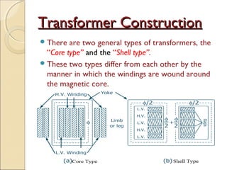
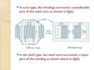
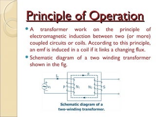
TRANSFORMERSTRANSFORMERS
What is a Transformer?What is a Transformer?
A Transformer is a device that transfers electrical
energy from one electrical circuit to another
electrical circuit through the medium of magnetic
field without changing its frequency.
The electric circuit which receives energy from the
supply is known as the “Primary winding” while the
circuit that transfers energy to the load is termed as
the “secondary winding”.
Various Important functions of Transformers
are:-
1) For increasing or decreasing the voltage or current
levels from one circuit to the other circuit.
2) For matching the impedance of a source and its
load for maximum power transfer in electronics
and control circuits.
3) For isolating DC while permitting the flow of AC
between the two circuits or for isolating one
circuit from another.
Transformer ConstructionTransformer Construction
There are two general types of transformers, the
“Core type” and the “Shell type”.
These two types differ from each other by the
manner in which the windings are wound around
the magnetic core.
In core type, the windings surround a considerable
part of the steel core as shown in fig(a)
In the shell type, the steel core surrounds a major
part of the winding as shown above in fig(b)
 Most of the flux is confined to the core however, some
flux leaks through the core legs and non magnetic
material surrounding the core. This flux is known as the
leakage flux.
 In core type this is achieved by placing half of the LV
winding over one leg and the rest half on the other leg.
Similar thing is done for the HV winding as well.
 As shown in the fig. LV winding is placed adjacent to the
core and HV outside, in order to minimize the amount of
insulation required.
 Shell type transformers are preferred for low-voltage
low-power levels whereas core type is used for high-
voltage high power levels.
Transformer suffers from mainly Four
types of losses:
a) Iron Loss
b) Copper Loss or Ohmic Loss
c) Stray losses (Leakage Flux)
d) Dielectric losses (Losses in insulating Material)
Principle of OperationPrinciple of Operation
A transformer work on the principle of
electromagnetic induction between two (or more)
coupled circuits or coils. According to this principle,
an emf is induced in a coil if it links a changing flux.
Schematic diagram of a two winding transformer
shown in the fig.
The primary winding ‘P’ is connected to an
alternating voltage source, therefore an alternating
current ‘Ie’ starts flowing through ‘N1’ turns.
The alternating mmf N1Ie sets up alternating flux Φ
which is confined to high permeability iron path
as shown in fig.
 The alternating flux induces voltage E1 in the
primary P and E2 in the secondary S. if the load
is connected across secondary a current will
start to flow.
Thus the transformer action requires the existence
of alternating mutual flux linking the various
winding on a common magnetic core.

Transformers

  • 1.
  • 2.
    What is aTransformer?What is a Transformer? A Transformer is a device that transfers electrical energy from one electrical circuit to another electrical circuit through the medium of magnetic field without changing its frequency. The electric circuit which receives energy from the supply is known as the “Primary winding” while the circuit that transfers energy to the load is termed as the “secondary winding”.
  • 3.
    Various Important functionsof Transformers are:- 1) For increasing or decreasing the voltage or current levels from one circuit to the other circuit. 2) For matching the impedance of a source and its load for maximum power transfer in electronics and control circuits. 3) For isolating DC while permitting the flow of AC between the two circuits or for isolating one circuit from another.
  • 4.
    Transformer ConstructionTransformer Construction Thereare two general types of transformers, the “Core type” and the “Shell type”. These two types differ from each other by the manner in which the windings are wound around the magnetic core.
  • 5.
    In core type,the windings surround a considerable part of the steel core as shown in fig(a) In the shell type, the steel core surrounds a major part of the winding as shown above in fig(b)
  • 6.
     Most ofthe flux is confined to the core however, some flux leaks through the core legs and non magnetic material surrounding the core. This flux is known as the leakage flux.  In core type this is achieved by placing half of the LV winding over one leg and the rest half on the other leg. Similar thing is done for the HV winding as well.  As shown in the fig. LV winding is placed adjacent to the core and HV outside, in order to minimize the amount of insulation required.  Shell type transformers are preferred for low-voltage low-power levels whereas core type is used for high- voltage high power levels.
  • 7.
    Transformer suffers frommainly Four types of losses: a) Iron Loss b) Copper Loss or Ohmic Loss c) Stray losses (Leakage Flux) d) Dielectric losses (Losses in insulating Material)
  • 8.
    Principle of OperationPrincipleof Operation A transformer work on the principle of electromagnetic induction between two (or more) coupled circuits or coils. According to this principle, an emf is induced in a coil if it links a changing flux. Schematic diagram of a two winding transformer shown in the fig.
  • 9.
    The primary winding‘P’ is connected to an alternating voltage source, therefore an alternating current ‘Ie’ starts flowing through ‘N1’ turns. The alternating mmf N1Ie sets up alternating flux Φ which is confined to high permeability iron path as shown in fig.
  • 10.
     The alternatingflux induces voltage E1 in the primary P and E2 in the secondary S. if the load is connected across secondary a current will start to flow. Thus the transformer action requires the existence of alternating mutual flux linking the various winding on a common magnetic core.