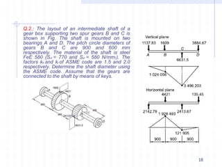
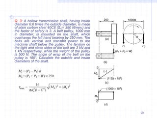
SlideShare a Scribd company logo
Design of Solid and Hollow Shafts
subjected to Different type of Loads
1
Introduction
Shaft is a rotating member and is used to transmit power. The
shaft may be hollow or solid.
In general, shaft has a circular cross-section.
The shaft is supported on bearings and it rotates a set of gears or
pulleys to transmit power.
The shaft is generally acted upon by
 Bending moment
 Torsion
 axial force.
Other two similar forms of a shaft are axle and spindle.
 Axle is a non-rotating member used for supporting rotating wheels
etc. and do not transmit any torque.
 Spindle is simply a short shaft. However, design method remains
the same for axle and spindle as that for a shaft.
2
Difference between Shafts, Spindle and Axle
3
SHAFT
4
Standard sizes of Shafts and Materials
Typical sizes of solid shaft that are available in the market are
0.5 mm increments
1. mm increments
2. mm increments
5.0 mm increments
 Up to 25 mm
 25 to 50 mm
 50 to 100 mm
 100 to 200 mm
Material for Shafts are
 ferrous, non-ferrous materials and non metals
depending on the application.
Some ferrous materials used in shafts are
 Hot-rolled plain carbon steel
 Cold-drawn plain carbon/alloy composition
 Alloy steels
5
Standard sizes of Shafts and Materials
In many cases, the surface of the shaft needs to be wear resistant
 Case hardening and carburizing
 Cyaniding and nitriding
6
Design considerations for shaft
Design based on Strength
 Design is carried out so that stress at any location of the shaft
should not exceed the material yield stress.
 No consideration for shaft deflection and shaft twist is included.
Design based on Stiffness
 The design is based on the allowable deflection and twist of the
shaft.
7
Design based on Strength
Bending stress
𝑏 𝐼 𝜋𝑑3
𝜎 = 𝑀𝑏𝑦
= 32𝑀𝑏, for solid shaft
𝑀𝑏 : Bending moment at the point of interest
d : Outer diameter of the solid shaft
𝐼: Area Moment of Inertia of shaft =
64
𝜋
𝑑4
𝑦: Distance of farthest fibre from neutral axis = 𝑑
2
𝜎𝑏 𝐼
= 𝑀𝑏𝑦
= 32𝑀𝑏
𝑜
𝜋𝑑3 1−𝐶4 , for hollow shaft
𝑀𝑏 : Bending moment at the point of interest
𝑑𝑜: Outer diameter of the hollow shaft, 𝑑𝑖: inside diameter of the hollow shaft
𝐶: Ratio of inside to outside diameter = 𝑑𝑖
𝑑
𝑜
𝐼: Area Moment of Inertia of shaft =
64 𝑜
𝜋
𝑑4
1 − 𝐶4
𝑦: Distance of farthest fibre from neutral axis = 𝑑𝑜
8
2
Design based on Strength
Axial stress
𝑡
𝜎 = 𝑃
=
4𝑃
𝐴 𝜋𝑑2
, for solid shaft
𝑃 : Axial force (tensile or compressive)
d : Outer diameter of the shaft
𝜋
4
𝐴: Area of cross section of shaft = 𝑑2
𝜎𝑡: Axial stress
𝑡
𝜎 = 𝑃
=
4𝑃
𝑜
𝐴 𝜋𝑑2 1−𝐶2
, for hollow shaft
𝑃 : Axial force (tensile or compressive)
4 𝑜 𝑖
9
𝐴: Area of cross section of shaft = 𝜋
𝑑2 − 𝑑2
𝜎𝑡: Axial stress
𝑑𝑜: Outer diameter of the hollow shaft, 𝑑𝑖: inside diameter of the hollow shaft
𝐶: Ratio of inside to outside diameter = 𝑑𝑖
𝑑
𝑜
Design based on Strength
Stress due to torsion
𝐽 𝜋𝑑3
𝜏 = 𝑀𝑡𝑟
= 16𝑀𝑡 , for solid shaft
𝑀𝑡 : Torque on the shaft
𝜏 : Shear stress due to torsion
𝑟: Radius of shaft
𝑑: Diameter of shaft
𝐽: Polar moment of inertia of shaft= 32
𝜋
𝑑4
𝐽
𝜏 = 𝑀𝑡𝑟
= 16𝑀𝑡
𝑜
𝜋𝑑3 1−𝐶4
, for hollow shaft
𝑀𝑡 : Torque on the shaft
𝜏 : Shear stress due to torsion
𝑟: Radius of shaft = 𝑑𝑜
2
𝐽: Polar moment of inertia of shaft= 𝑑4 − 𝑑4 =
𝜋
32 32
𝑜 𝑖 𝑜
𝜋
𝑑4
1 − 𝐶4
10
𝑑𝑜: Outer diameter of the hollow shaft, 𝑑𝑖: inside diameter of the hollow shaft
𝐶: Ratio of inside to outside diameter = 𝑑𝑖
𝑑
𝑜
Design based on Strength
Shafts subjected to Combined Load
1) Shaft subjected to a combination of axial force, bending moment
and torsional moment
2)Shaft subjected to a combination of bending moment
and torsional moment
The principal stress is given by,
The principal shear stress is given by,
11
Design based on Strength
(i) Maximum Principal Stress Theory
for Solid shaft
Shaft subjected to a combination of bending moment and torsional moment
The principal stress is given by,
or
The permissible value of maximum principal stress is given by,
is called ‘equivalent’ bending moment.
principal stress theory gives good predictions for brittle
Maximum
materials.
12
Design based on Strength
(i) Maximum Principal Stress Theory
for hollow shaft
Shaft subjected to a combination of bending moment and torsional moment
32𝑀𝑏
𝑜
𝜋𝑑3 1−𝐶4
𝜎𝑥 = 𝜎𝑏 = 𝜏 = 16𝑀𝑡
𝑜
𝜋𝑑3 1−𝐶4
The principal stress is given by,
The permissible value of maximum principal stress is given by,
13
Design based on Strength
(i) Maximum Shear Stress Theory
For Solid Shaft
Shaft subjected to a combination of bending moment and torsional moment
The principal shear stress is given by,
or
The permissible value of maximum shear stress is given by,
is called ‘equivalent’ torsional moment.
Maximum shear stress theory gives good predictions for ductile
materials.
Maximum shear stress theory is applied for shaft design
14
Design based on Strength
(i) Maximum Shear Stress Theory
For Hollow Shaft
Shaft subjected to a combination of bending moment and torsional moment
is given by,
or
The permissible value of maximum shear stress is given by,
32𝑀𝑏
𝑜
𝜋𝑑3 1−𝐶4
𝜎𝑥 = 𝜎𝑏 = 𝜏 =
The principal shear stress
16𝑀𝑡
𝑜
𝜋𝑑3 1−𝐶4
is called ‘equivalent’ torsional moment.
Maximum shear stress theory gives good predictions for ductile
materials.
Maximum shear stress theory is applied for shaft design
15
Design based on Strength
ASME CODE FOR SHAFT DESIGN
• For the shaft without keyways,
• If keyways are present, the above values are to be reduced by
25 per cent.
• The ASME code is based on maximum shear stress theory of
failure.
• For shaft design according to ASME code
where
16
Q.1.: The layout of a transmission shaft
carrying two pulleys B and C and
supported on bearings A and D is shown in
Fig. Power is supplied to the shaft by
means of a vertical belt on the pulley B,
which is then transmitted to the pulley C
carrying a horizontal belt. The maximum
tension in the belt on the pulley B is 2.5
kN. The angle of wrap for both the pulleys
is 180° and the coefficient of friction is
0.24. The shaft is made of plain carbon
steel 30C8 (Syt = 400 N/mm2) and the factor
of safety is 3. Determine the shaft diameter
on strength basis.
17
Q.2.: The layout of an intermediate shaft of a
gear box supporting two spur gears B and C is
shown in Fig. The shaft is mounted on two
bearings A and D. The pitch circle diameters of
gears B and C are 900 and 600 mm
respectively. The material of the shaft is steel
FeE 580 (Sut = 770 and Syt = 580 N/mm2). The
factors kb and kt of ASME code are 1.5 and 2.0
respectively. Determine the shaft diameter using
the ASME code. Assume that the gears are
connected to the shaft by means of keys.
18
Q. 3: A hollow transmission shaft, having inside
diameter 0.6 times the outside diameter, is made
of plain carbon steel 40C8 (Syt = 380 N/mm2) and
the factor of safety is 3. A belt pulley, 1000 mm
in diameter, is mounted on the shaft, which
overhangs the left hand bearing by 250 mm. The
belts are vertical and transmit power to the
machine shaft below the pulley. The tension on
the tight and slack sides of the belt are 3 kN and
1 kN respectively, while the weight of the pulley
is 500 N. The angle of wrap of the belt on the
pulley is 180°. Calculate the outside and inside
diameters of the shaft.
19
Q. 4: A propeller shaft is required to transmit 50kW power at 600 rpm. It is a
hollow shaft, having an inside diameter 0.8 times of the outside diameter. It is made
of steel (Syt = 380 N/mm2) and the factor of safety is 4. Calculate the inside and
outside diameters of the shaft. Assume (Ssy = 0.5Syt)
20

More Related Content

Similar to 99999599.pptx

U3 design of connecting rod-(i section, big&small eng, bolt, whipping str...
U3 design of connecting rod-(i section, big&small eng, bolt, whipping str...U3 design of connecting rod-(i section, big&small eng, bolt, whipping str...
U3 design of connecting rod-(i section, big&small eng, bolt, whipping str...
karuppusamy pitchai
 
Unit 2 Shafts and Coupling.pptx
Unit 2 Shafts and Coupling.pptxUnit 2 Shafts and Coupling.pptx
Unit 2 Shafts and Coupling.pptx
Charunnath S V
 
unit2designofshaft-170719110901 (1) (1).pptx
unit2designofshaft-170719110901 (1) (1).pptxunit2designofshaft-170719110901 (1) (1).pptx
unit2designofshaft-170719110901 (1) (1).pptx
HarikumarA4
 
Final year project
Final year projectFinal year project
Final year project
RohitMeshram15
 
Design of machine element II.pptx
Design of machine element II.pptxDesign of machine element II.pptx
Design of machine element II.pptx
AdugnaFikadu
 
Shaft
ShaftShaft
Unit 7-60
Unit 7-60Unit 7-60
Unit 7-60
Rafael Dela Pena
 
Design of threaded jopints and mechanical spring
Design of threaded jopints and mechanical springDesign of threaded jopints and mechanical spring
Design of threaded jopints and mechanical spring
forcealien03
 
torsion
torsiontorsion
torsion
sssshekhar
 
Simple torsion equation
Simple torsion equationSimple torsion equation
Simple torsion equation
sushma chinta
 
Design of.pptx
Design of.pptxDesign of.pptx
Design of.pptx
ArchanaMaske2
 
Flat belt pulleys
Flat belt pulleysFlat belt pulleys
Flat belt pulleys
Mohamed Mohamed El-Sayed
 
3 shaft stress in shafts
3 shaft   stress in shafts3 shaft   stress in shafts
3 shaft stress in shafts
Dr.R. SELVAM
 
Shafts and Shafts Components
Shafts and Shafts ComponentsShafts and Shafts Components
Shafts and Shafts Components
V-Motech
 
Unit 5 Design of Threaded and Welded Joints
Unit 5 Design of Threaded and Welded JointsUnit 5 Design of Threaded and Welded Joints
Unit 5 Design of Threaded and Welded Joints
Mahesh Shinde
 
Design and Construction of a Connecting rod
Design and Construction of a Connecting rodDesign and Construction of a Connecting rod
Design and Construction of a Connecting rod
Faisal Niloy
 
Design & Construction of a Connecting rod
Design & Construction of a Connecting rodDesign & Construction of a Connecting rod
Design & Construction of a Connecting rod
Faisal Niloy
 
ch-02_cotter-joint-knuckle-joint-design.pdf
ch-02_cotter-joint-knuckle-joint-design.pdfch-02_cotter-joint-knuckle-joint-design.pdf
ch-02_cotter-joint-knuckle-joint-design.pdf
Praveen Kumar
 
Module 5.pdf
Module 5.pdfModule 5.pdf
Module 5.pdf
Shahnawaz742629
 
connecting rod
connecting rodconnecting rod
connecting rod
Sampath Kumar
 

Similar to 99999599.pptx (20)

U3 design of connecting rod-(i section, big&small eng, bolt, whipping str...
U3 design of connecting rod-(i section, big&small eng, bolt, whipping str...U3 design of connecting rod-(i section, big&small eng, bolt, whipping str...
U3 design of connecting rod-(i section, big&small eng, bolt, whipping str...
 
Unit 2 Shafts and Coupling.pptx
Unit 2 Shafts and Coupling.pptxUnit 2 Shafts and Coupling.pptx
Unit 2 Shafts and Coupling.pptx
 
unit2designofshaft-170719110901 (1) (1).pptx
unit2designofshaft-170719110901 (1) (1).pptxunit2designofshaft-170719110901 (1) (1).pptx
unit2designofshaft-170719110901 (1) (1).pptx
 
Final year project
Final year projectFinal year project
Final year project
 
Design of machine element II.pptx
Design of machine element II.pptxDesign of machine element II.pptx
Design of machine element II.pptx
 
Shaft
ShaftShaft
Shaft
 
Unit 7-60
Unit 7-60Unit 7-60
Unit 7-60
 
Design of threaded jopints and mechanical spring
Design of threaded jopints and mechanical springDesign of threaded jopints and mechanical spring
Design of threaded jopints and mechanical spring
 
torsion
torsiontorsion
torsion
 
Simple torsion equation
Simple torsion equationSimple torsion equation
Simple torsion equation
 
Design of.pptx
Design of.pptxDesign of.pptx
Design of.pptx
 
Flat belt pulleys
Flat belt pulleysFlat belt pulleys
Flat belt pulleys
 
3 shaft stress in shafts
3 shaft   stress in shafts3 shaft   stress in shafts
3 shaft stress in shafts
 
Shafts and Shafts Components
Shafts and Shafts ComponentsShafts and Shafts Components
Shafts and Shafts Components
 
Unit 5 Design of Threaded and Welded Joints
Unit 5 Design of Threaded and Welded JointsUnit 5 Design of Threaded and Welded Joints
Unit 5 Design of Threaded and Welded Joints
 
Design and Construction of a Connecting rod
Design and Construction of a Connecting rodDesign and Construction of a Connecting rod
Design and Construction of a Connecting rod
 
Design & Construction of a Connecting rod
Design & Construction of a Connecting rodDesign & Construction of a Connecting rod
Design & Construction of a Connecting rod
 
ch-02_cotter-joint-knuckle-joint-design.pdf
ch-02_cotter-joint-knuckle-joint-design.pdfch-02_cotter-joint-knuckle-joint-design.pdf
ch-02_cotter-joint-knuckle-joint-design.pdf
 
Module 5.pdf
Module 5.pdfModule 5.pdf
Module 5.pdf
 
connecting rod
connecting rodconnecting rod
connecting rod
 

More from HarikumarA4

Belt Drives_2.pdf
Belt Drives_2.pdfBelt Drives_2.pdf
Belt Drives_2.pdf
HarikumarA4
 
Belt Drives_1.pptx
Belt Drives_1.pptxBelt Drives_1.pptx
Belt Drives_1.pptx
HarikumarA4
 
PPT- CDT-8.pptx
PPT- CDT-8.pptxPPT- CDT-8.pptx
PPT- CDT-8.pptx
HarikumarA4
 
clutch.ppt
clutch.pptclutch.ppt
clutch.ppt
HarikumarA4
 
BRAKE_SYSTEM.pptx
BRAKE_SYSTEM.pptxBRAKE_SYSTEM.pptx
BRAKE_SYSTEM.pptx
HarikumarA4
 
Stresses in flywheel rim.pptx
Stresses in flywheel rim.pptxStresses in flywheel rim.pptx
Stresses in flywheel rim.pptx
HarikumarA4
 
V-belt Drives.pptx
V-belt Drives.pptxV-belt Drives.pptx
V-belt Drives.pptx
HarikumarA4
 
Sliding-Contact-Bearings.ppt
Sliding-Contact-Bearings.pptSliding-Contact-Bearings.ppt
Sliding-Contact-Bearings.ppt
HarikumarA4
 
pp-chapter 7.ppt
pp-chapter 7.pptpp-chapter 7.ppt
pp-chapter 7.ppt
HarikumarA4
 
engineering-graphics.pdf
engineering-graphics.pdfengineering-graphics.pdf
engineering-graphics.pdf
HarikumarA4
 

More from HarikumarA4 (10)

Belt Drives_2.pdf
Belt Drives_2.pdfBelt Drives_2.pdf
Belt Drives_2.pdf
 
Belt Drives_1.pptx
Belt Drives_1.pptxBelt Drives_1.pptx
Belt Drives_1.pptx
 
PPT- CDT-8.pptx
PPT- CDT-8.pptxPPT- CDT-8.pptx
PPT- CDT-8.pptx
 
clutch.ppt
clutch.pptclutch.ppt
clutch.ppt
 
BRAKE_SYSTEM.pptx
BRAKE_SYSTEM.pptxBRAKE_SYSTEM.pptx
BRAKE_SYSTEM.pptx
 
Stresses in flywheel rim.pptx
Stresses in flywheel rim.pptxStresses in flywheel rim.pptx
Stresses in flywheel rim.pptx
 
V-belt Drives.pptx
V-belt Drives.pptxV-belt Drives.pptx
V-belt Drives.pptx
 
Sliding-Contact-Bearings.ppt
Sliding-Contact-Bearings.pptSliding-Contact-Bearings.ppt
Sliding-Contact-Bearings.ppt
 
pp-chapter 7.ppt
pp-chapter 7.pptpp-chapter 7.ppt
pp-chapter 7.ppt
 
engineering-graphics.pdf
engineering-graphics.pdfengineering-graphics.pdf
engineering-graphics.pdf
 

Recently uploaded

Technical Drawings introduction to drawing of prisms
Technical Drawings introduction to drawing of prismsTechnical Drawings introduction to drawing of prisms
Technical Drawings introduction to drawing of prisms
heavyhaig
 
basic-wireline-operations-course-mahmoud-f-radwan.pdf
basic-wireline-operations-course-mahmoud-f-radwan.pdfbasic-wireline-operations-course-mahmoud-f-radwan.pdf
basic-wireline-operations-course-mahmoud-f-radwan.pdf
NidhalKahouli2
 
132/33KV substation case study Presentation
132/33KV substation case study Presentation132/33KV substation case study Presentation
132/33KV substation case study Presentation
kandramariana6
 
ML Based Model for NIDS MSc Updated Presentation.v2.pptx
ML Based Model for NIDS MSc Updated Presentation.v2.pptxML Based Model for NIDS MSc Updated Presentation.v2.pptx
ML Based Model for NIDS MSc Updated Presentation.v2.pptx
JamalHussainArman
 
哪里办理(csu毕业证书)查尔斯特大学毕业证硕士学历原版一模一样
哪里办理(csu毕业证书)查尔斯特大学毕业证硕士学历原版一模一样哪里办理(csu毕业证书)查尔斯特大学毕业证硕士学历原版一模一样
哪里办理(csu毕业证书)查尔斯特大学毕业证硕士学历原版一模一样
insn4465
 
Manufacturing Process of molasses based distillery ppt.pptx
Manufacturing Process of molasses based distillery ppt.pptxManufacturing Process of molasses based distillery ppt.pptx
Manufacturing Process of molasses based distillery ppt.pptx
Madan Karki
 
Wearable antenna for antenna applications
Wearable antenna for antenna applicationsWearable antenna for antenna applications
Wearable antenna for antenna applications
Madhumitha Jayaram
 
Generative AI leverages algorithms to create various forms of content
Generative AI leverages algorithms to create various forms of contentGenerative AI leverages algorithms to create various forms of content
Generative AI leverages algorithms to create various forms of content
Hitesh Mohapatra
 
spirit beverages ppt without graphics.pptx
spirit beverages ppt without graphics.pptxspirit beverages ppt without graphics.pptx
spirit beverages ppt without graphics.pptx
Madan Karki
 
Recycled Concrete Aggregate in Construction Part III
Recycled Concrete Aggregate in Construction Part IIIRecycled Concrete Aggregate in Construction Part III
Recycled Concrete Aggregate in Construction Part III
Aditya Rajan Patra
 
International Conference on NLP, Artificial Intelligence, Machine Learning an...
International Conference on NLP, Artificial Intelligence, Machine Learning an...International Conference on NLP, Artificial Intelligence, Machine Learning an...
International Conference on NLP, Artificial Intelligence, Machine Learning an...
gerogepatton
 
New techniques for characterising damage in rock slopes.pdf
New techniques for characterising damage in rock slopes.pdfNew techniques for characterising damage in rock slopes.pdf
New techniques for characterising damage in rock slopes.pdf
wisnuprabawa3
 
sieving analysis and results interpretation
sieving analysis and results interpretationsieving analysis and results interpretation
sieving analysis and results interpretation
ssuser36d3051
 
Question paper of renewable energy sources
Question paper of renewable energy sourcesQuestion paper of renewable energy sources
Question paper of renewable energy sources
mahammadsalmanmech
 
Low power architecture of logic gates using adiabatic techniques
Low power architecture of logic gates using adiabatic techniquesLow power architecture of logic gates using adiabatic techniques
Low power architecture of logic gates using adiabatic techniques
nooriasukmaningtyas
 
Advanced control scheme of doubly fed induction generator for wind turbine us...
Advanced control scheme of doubly fed induction generator for wind turbine us...Advanced control scheme of doubly fed induction generator for wind turbine us...
Advanced control scheme of doubly fed induction generator for wind turbine us...
IJECEIAES
 
bank management system in java and mysql report1.pdf
bank management system in java and mysql report1.pdfbank management system in java and mysql report1.pdf
bank management system in java and mysql report1.pdf
Divyam548318
 
A review on techniques and modelling methodologies used for checking electrom...
A review on techniques and modelling methodologies used for checking electrom...A review on techniques and modelling methodologies used for checking electrom...
A review on techniques and modelling methodologies used for checking electrom...
nooriasukmaningtyas
 
CHINA’S GEO-ECONOMIC OUTREACH IN CENTRAL ASIAN COUNTRIES AND FUTURE PROSPECT
CHINA’S GEO-ECONOMIC OUTREACH IN CENTRAL ASIAN COUNTRIES AND FUTURE PROSPECTCHINA’S GEO-ECONOMIC OUTREACH IN CENTRAL ASIAN COUNTRIES AND FUTURE PROSPECT
CHINA’S GEO-ECONOMIC OUTREACH IN CENTRAL ASIAN COUNTRIES AND FUTURE PROSPECT
jpsjournal1
 
Understanding Inductive Bias in Machine Learning
Understanding Inductive Bias in Machine LearningUnderstanding Inductive Bias in Machine Learning
Understanding Inductive Bias in Machine Learning
SUTEJAS
 

Recently uploaded (20)

Technical Drawings introduction to drawing of prisms
Technical Drawings introduction to drawing of prismsTechnical Drawings introduction to drawing of prisms
Technical Drawings introduction to drawing of prisms
 
basic-wireline-operations-course-mahmoud-f-radwan.pdf
basic-wireline-operations-course-mahmoud-f-radwan.pdfbasic-wireline-operations-course-mahmoud-f-radwan.pdf
basic-wireline-operations-course-mahmoud-f-radwan.pdf
 
132/33KV substation case study Presentation
132/33KV substation case study Presentation132/33KV substation case study Presentation
132/33KV substation case study Presentation
 
ML Based Model for NIDS MSc Updated Presentation.v2.pptx
ML Based Model for NIDS MSc Updated Presentation.v2.pptxML Based Model for NIDS MSc Updated Presentation.v2.pptx
ML Based Model for NIDS MSc Updated Presentation.v2.pptx
 
哪里办理(csu毕业证书)查尔斯特大学毕业证硕士学历原版一模一样
哪里办理(csu毕业证书)查尔斯特大学毕业证硕士学历原版一模一样哪里办理(csu毕业证书)查尔斯特大学毕业证硕士学历原版一模一样
哪里办理(csu毕业证书)查尔斯特大学毕业证硕士学历原版一模一样
 
Manufacturing Process of molasses based distillery ppt.pptx
Manufacturing Process of molasses based distillery ppt.pptxManufacturing Process of molasses based distillery ppt.pptx
Manufacturing Process of molasses based distillery ppt.pptx
 
Wearable antenna for antenna applications
Wearable antenna for antenna applicationsWearable antenna for antenna applications
Wearable antenna for antenna applications
 
Generative AI leverages algorithms to create various forms of content
Generative AI leverages algorithms to create various forms of contentGenerative AI leverages algorithms to create various forms of content
Generative AI leverages algorithms to create various forms of content
 
spirit beverages ppt without graphics.pptx
spirit beverages ppt without graphics.pptxspirit beverages ppt without graphics.pptx
spirit beverages ppt without graphics.pptx
 
Recycled Concrete Aggregate in Construction Part III
Recycled Concrete Aggregate in Construction Part IIIRecycled Concrete Aggregate in Construction Part III
Recycled Concrete Aggregate in Construction Part III
 
International Conference on NLP, Artificial Intelligence, Machine Learning an...
International Conference on NLP, Artificial Intelligence, Machine Learning an...International Conference on NLP, Artificial Intelligence, Machine Learning an...
International Conference on NLP, Artificial Intelligence, Machine Learning an...
 
New techniques for characterising damage in rock slopes.pdf
New techniques for characterising damage in rock slopes.pdfNew techniques for characterising damage in rock slopes.pdf
New techniques for characterising damage in rock slopes.pdf
 
sieving analysis and results interpretation
sieving analysis and results interpretationsieving analysis and results interpretation
sieving analysis and results interpretation
 
Question paper of renewable energy sources
Question paper of renewable energy sourcesQuestion paper of renewable energy sources
Question paper of renewable energy sources
 
Low power architecture of logic gates using adiabatic techniques
Low power architecture of logic gates using adiabatic techniquesLow power architecture of logic gates using adiabatic techniques
Low power architecture of logic gates using adiabatic techniques
 
Advanced control scheme of doubly fed induction generator for wind turbine us...
Advanced control scheme of doubly fed induction generator for wind turbine us...Advanced control scheme of doubly fed induction generator for wind turbine us...
Advanced control scheme of doubly fed induction generator for wind turbine us...
 
bank management system in java and mysql report1.pdf
bank management system in java and mysql report1.pdfbank management system in java and mysql report1.pdf
bank management system in java and mysql report1.pdf
 
A review on techniques and modelling methodologies used for checking electrom...
A review on techniques and modelling methodologies used for checking electrom...A review on techniques and modelling methodologies used for checking electrom...
A review on techniques and modelling methodologies used for checking electrom...
 
CHINA’S GEO-ECONOMIC OUTREACH IN CENTRAL ASIAN COUNTRIES AND FUTURE PROSPECT
CHINA’S GEO-ECONOMIC OUTREACH IN CENTRAL ASIAN COUNTRIES AND FUTURE PROSPECTCHINA’S GEO-ECONOMIC OUTREACH IN CENTRAL ASIAN COUNTRIES AND FUTURE PROSPECT
CHINA’S GEO-ECONOMIC OUTREACH IN CENTRAL ASIAN COUNTRIES AND FUTURE PROSPECT
 
Understanding Inductive Bias in Machine Learning
Understanding Inductive Bias in Machine LearningUnderstanding Inductive Bias in Machine Learning
Understanding Inductive Bias in Machine Learning
 

99999599.pptx

  • 1. Design of Solid and Hollow Shafts subjected to Different type of Loads 1
  • 2. Introduction Shaft is a rotating member and is used to transmit power. The shaft may be hollow or solid. In general, shaft has a circular cross-section. The shaft is supported on bearings and it rotates a set of gears or pulleys to transmit power. The shaft is generally acted upon by  Bending moment  Torsion  axial force. Other two similar forms of a shaft are axle and spindle.  Axle is a non-rotating member used for supporting rotating wheels etc. and do not transmit any torque.  Spindle is simply a short shaft. However, design method remains the same for axle and spindle as that for a shaft. 2
  • 3. Difference between Shafts, Spindle and Axle 3
  • 5. Standard sizes of Shafts and Materials Typical sizes of solid shaft that are available in the market are 0.5 mm increments 1. mm increments 2. mm increments 5.0 mm increments  Up to 25 mm  25 to 50 mm  50 to 100 mm  100 to 200 mm Material for Shafts are  ferrous, non-ferrous materials and non metals depending on the application. Some ferrous materials used in shafts are  Hot-rolled plain carbon steel  Cold-drawn plain carbon/alloy composition  Alloy steels 5
  • 6. Standard sizes of Shafts and Materials In many cases, the surface of the shaft needs to be wear resistant  Case hardening and carburizing  Cyaniding and nitriding 6
  • 7. Design considerations for shaft Design based on Strength  Design is carried out so that stress at any location of the shaft should not exceed the material yield stress.  No consideration for shaft deflection and shaft twist is included. Design based on Stiffness  The design is based on the allowable deflection and twist of the shaft. 7
  • 8. Design based on Strength Bending stress 𝑏 𝐼 𝜋𝑑3 𝜎 = 𝑀𝑏𝑦 = 32𝑀𝑏, for solid shaft 𝑀𝑏 : Bending moment at the point of interest d : Outer diameter of the solid shaft 𝐼: Area Moment of Inertia of shaft = 64 𝜋 𝑑4 𝑦: Distance of farthest fibre from neutral axis = 𝑑 2 𝜎𝑏 𝐼 = 𝑀𝑏𝑦 = 32𝑀𝑏 𝑜 𝜋𝑑3 1−𝐶4 , for hollow shaft 𝑀𝑏 : Bending moment at the point of interest 𝑑𝑜: Outer diameter of the hollow shaft, 𝑑𝑖: inside diameter of the hollow shaft 𝐶: Ratio of inside to outside diameter = 𝑑𝑖 𝑑 𝑜 𝐼: Area Moment of Inertia of shaft = 64 𝑜 𝜋 𝑑4 1 − 𝐶4 𝑦: Distance of farthest fibre from neutral axis = 𝑑𝑜 8 2
  • 9. Design based on Strength Axial stress 𝑡 𝜎 = 𝑃 = 4𝑃 𝐴 𝜋𝑑2 , for solid shaft 𝑃 : Axial force (tensile or compressive) d : Outer diameter of the shaft 𝜋 4 𝐴: Area of cross section of shaft = 𝑑2 𝜎𝑡: Axial stress 𝑡 𝜎 = 𝑃 = 4𝑃 𝑜 𝐴 𝜋𝑑2 1−𝐶2 , for hollow shaft 𝑃 : Axial force (tensile or compressive) 4 𝑜 𝑖 9 𝐴: Area of cross section of shaft = 𝜋 𝑑2 − 𝑑2 𝜎𝑡: Axial stress 𝑑𝑜: Outer diameter of the hollow shaft, 𝑑𝑖: inside diameter of the hollow shaft 𝐶: Ratio of inside to outside diameter = 𝑑𝑖 𝑑 𝑜
  • 10. Design based on Strength Stress due to torsion 𝐽 𝜋𝑑3 𝜏 = 𝑀𝑡𝑟 = 16𝑀𝑡 , for solid shaft 𝑀𝑡 : Torque on the shaft 𝜏 : Shear stress due to torsion 𝑟: Radius of shaft 𝑑: Diameter of shaft 𝐽: Polar moment of inertia of shaft= 32 𝜋 𝑑4 𝐽 𝜏 = 𝑀𝑡𝑟 = 16𝑀𝑡 𝑜 𝜋𝑑3 1−𝐶4 , for hollow shaft 𝑀𝑡 : Torque on the shaft 𝜏 : Shear stress due to torsion 𝑟: Radius of shaft = 𝑑𝑜 2 𝐽: Polar moment of inertia of shaft= 𝑑4 − 𝑑4 = 𝜋 32 32 𝑜 𝑖 𝑜 𝜋 𝑑4 1 − 𝐶4 10 𝑑𝑜: Outer diameter of the hollow shaft, 𝑑𝑖: inside diameter of the hollow shaft 𝐶: Ratio of inside to outside diameter = 𝑑𝑖 𝑑 𝑜
  • 11. Design based on Strength Shafts subjected to Combined Load 1) Shaft subjected to a combination of axial force, bending moment and torsional moment 2)Shaft subjected to a combination of bending moment and torsional moment The principal stress is given by, The principal shear stress is given by, 11
  • 12. Design based on Strength (i) Maximum Principal Stress Theory for Solid shaft Shaft subjected to a combination of bending moment and torsional moment The principal stress is given by, or The permissible value of maximum principal stress is given by, is called ‘equivalent’ bending moment. principal stress theory gives good predictions for brittle Maximum materials. 12
  • 13. Design based on Strength (i) Maximum Principal Stress Theory for hollow shaft Shaft subjected to a combination of bending moment and torsional moment 32𝑀𝑏 𝑜 𝜋𝑑3 1−𝐶4 𝜎𝑥 = 𝜎𝑏 = 𝜏 = 16𝑀𝑡 𝑜 𝜋𝑑3 1−𝐶4 The principal stress is given by, The permissible value of maximum principal stress is given by, 13
  • 14. Design based on Strength (i) Maximum Shear Stress Theory For Solid Shaft Shaft subjected to a combination of bending moment and torsional moment The principal shear stress is given by, or The permissible value of maximum shear stress is given by, is called ‘equivalent’ torsional moment. Maximum shear stress theory gives good predictions for ductile materials. Maximum shear stress theory is applied for shaft design 14
  • 15. Design based on Strength (i) Maximum Shear Stress Theory For Hollow Shaft Shaft subjected to a combination of bending moment and torsional moment is given by, or The permissible value of maximum shear stress is given by, 32𝑀𝑏 𝑜 𝜋𝑑3 1−𝐶4 𝜎𝑥 = 𝜎𝑏 = 𝜏 = The principal shear stress 16𝑀𝑡 𝑜 𝜋𝑑3 1−𝐶4 is called ‘equivalent’ torsional moment. Maximum shear stress theory gives good predictions for ductile materials. Maximum shear stress theory is applied for shaft design 15
  • 16. Design based on Strength ASME CODE FOR SHAFT DESIGN • For the shaft without keyways, • If keyways are present, the above values are to be reduced by 25 per cent. • The ASME code is based on maximum shear stress theory of failure. • For shaft design according to ASME code where 16
  • 17. Q.1.: The layout of a transmission shaft carrying two pulleys B and C and supported on bearings A and D is shown in Fig. Power is supplied to the shaft by means of a vertical belt on the pulley B, which is then transmitted to the pulley C carrying a horizontal belt. The maximum tension in the belt on the pulley B is 2.5 kN. The angle of wrap for both the pulleys is 180° and the coefficient of friction is 0.24. The shaft is made of plain carbon steel 30C8 (Syt = 400 N/mm2) and the factor of safety is 3. Determine the shaft diameter on strength basis. 17
  • 18. Q.2.: The layout of an intermediate shaft of a gear box supporting two spur gears B and C is shown in Fig. The shaft is mounted on two bearings A and D. The pitch circle diameters of gears B and C are 900 and 600 mm respectively. The material of the shaft is steel FeE 580 (Sut = 770 and Syt = 580 N/mm2). The factors kb and kt of ASME code are 1.5 and 2.0 respectively. Determine the shaft diameter using the ASME code. Assume that the gears are connected to the shaft by means of keys. 18
  • 19. Q. 3: A hollow transmission shaft, having inside diameter 0.6 times the outside diameter, is made of plain carbon steel 40C8 (Syt = 380 N/mm2) and the factor of safety is 3. A belt pulley, 1000 mm in diameter, is mounted on the shaft, which overhangs the left hand bearing by 250 mm. The belts are vertical and transmit power to the machine shaft below the pulley. The tension on the tight and slack sides of the belt are 3 kN and 1 kN respectively, while the weight of the pulley is 500 N. The angle of wrap of the belt on the pulley is 180°. Calculate the outside and inside diameters of the shaft. 19
  • 20. Q. 4: A propeller shaft is required to transmit 50kW power at 600 rpm. It is a hollow shaft, having an inside diameter 0.8 times of the outside diameter. It is made of steel (Syt = 380 N/mm2) and the factor of safety is 4. Calculate the inside and outside diameters of the shaft. Assume (Ssy = 0.5Syt) 20