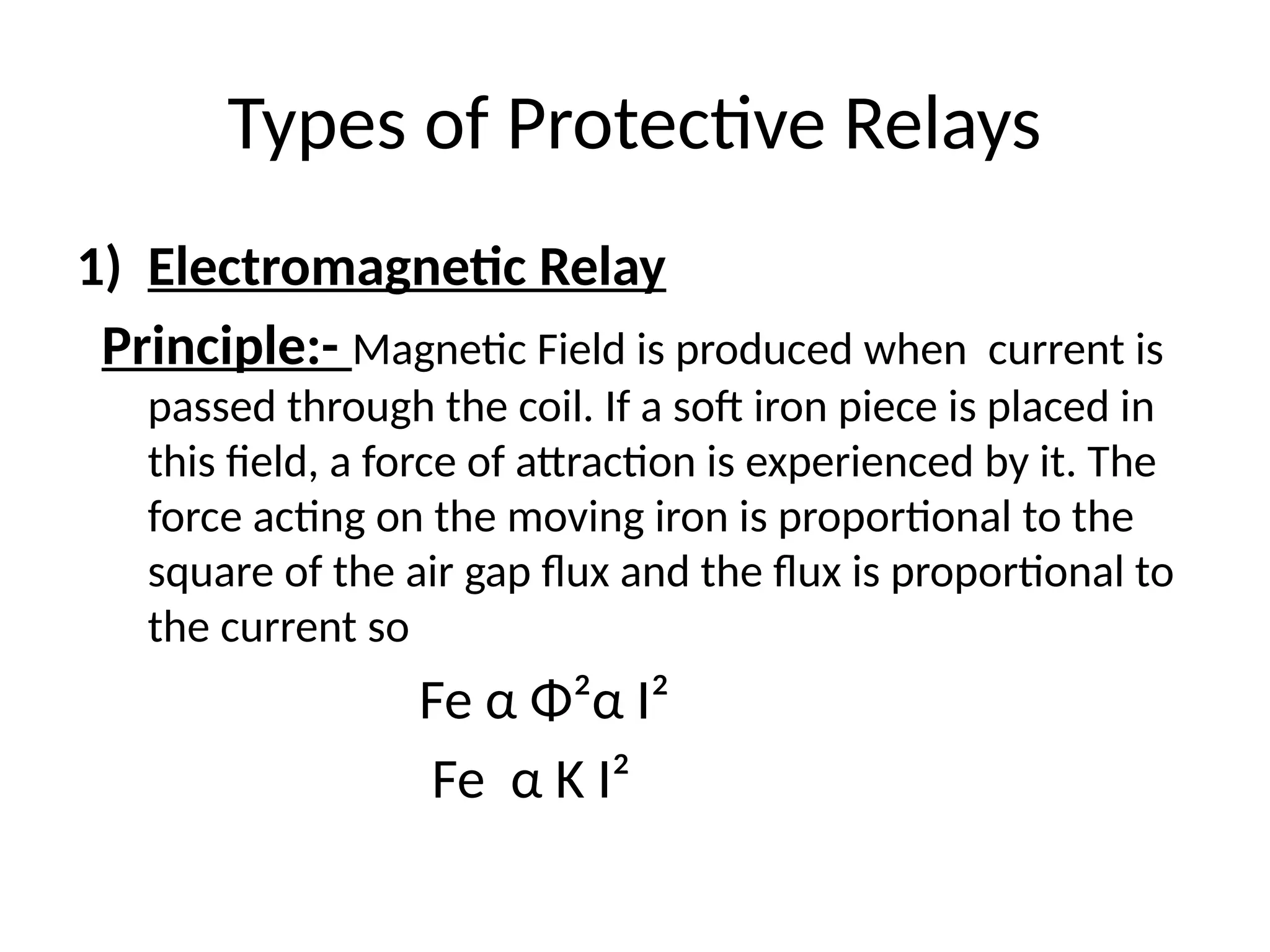
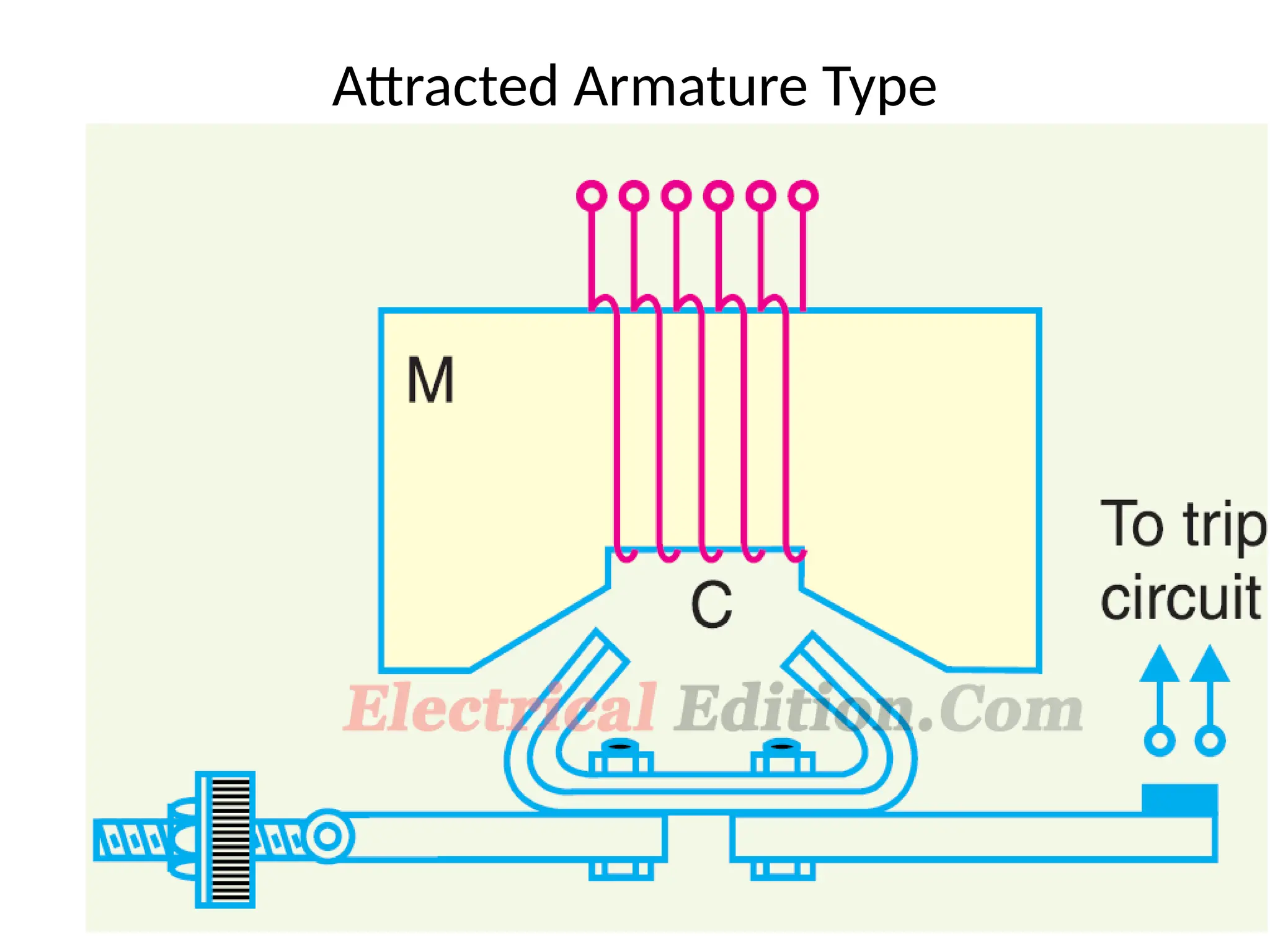
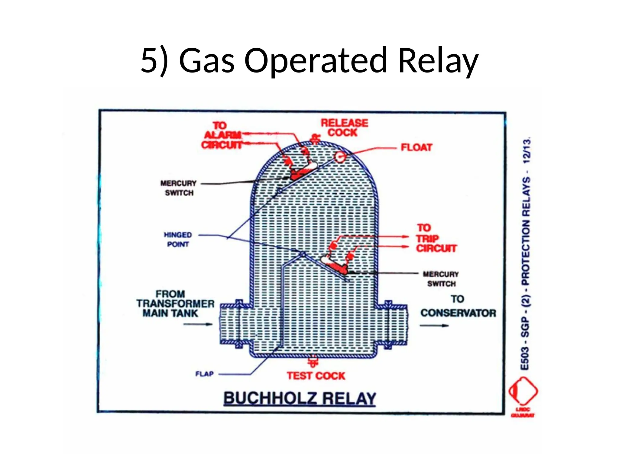
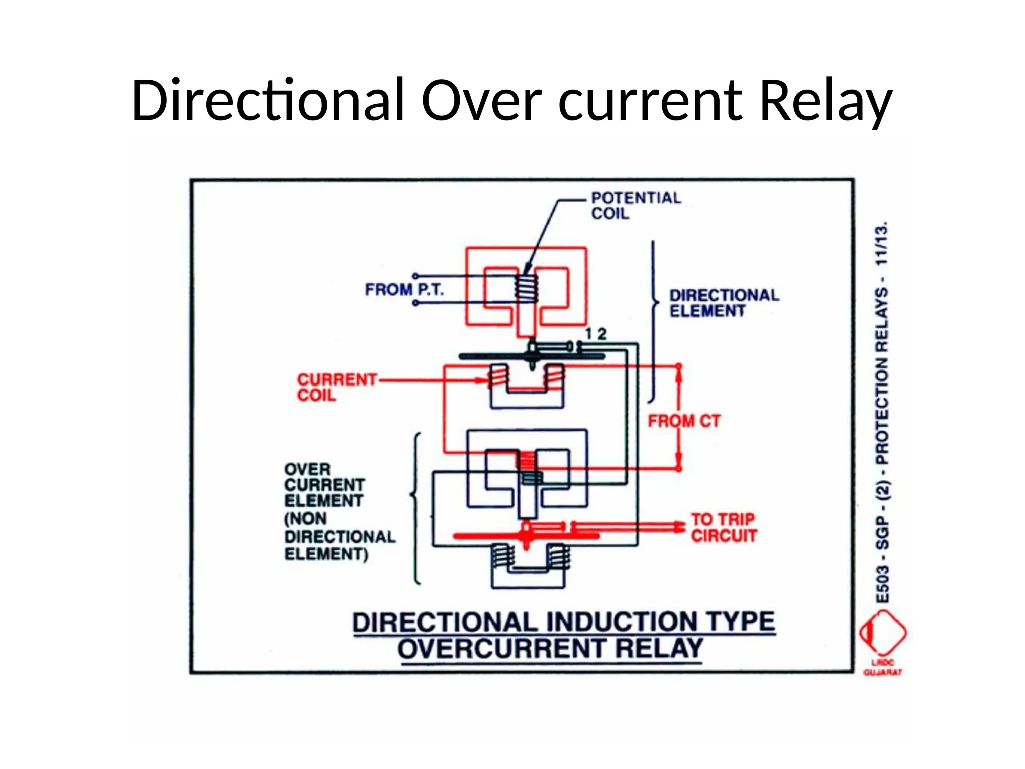
SGP
Chapter-3
Protective Relays
Types of Protective Relays
1) Electromagnetic Relay
Principle:- Magnetic Field is produced when current is
passed through the coil. If a soft iron piece is placed in
this field, a force of attraction is experienced by it. The
force acting on the moving iron is proportional to the
square of the air gap flux and the flux is proportional to
the current so
Fe α Φ²α I²
Fe α K I²
Types of Electromagnetic Attraction Relay
I) Attracted Armature Type
II) Solenoid type
III) Balanced beam type
Attracted Armature Type
Solenoid type Relay
Conti…..
i) Shading band method of Preventing chatting
of the contacts:-
Conti….
ii) Condenser method of preventing chattering
of the contacts And Vector Diagram:-
Attracted Armature type Polarized
Relay
Balanced Beam Type Relay
I1 = Current Flowing through the operating coil
I2 = Current flowing through the restraining coil
Neglecting the spring force,
Net force = K1 I1² - K2 I²
The two forces become equal when the relay operates
K1 I1² = K2 I²
I1/I2 = √K2/K1
Characteristic..
Types of Balanced Beam Relay
1) Current Relay :- The Current are supplied through the
secondary windings of CTs.
I1/I2 = √K2/K1
2) Voltage Relay:- In this relay the two coils are excited the voltage
sources.
K1 V1² - K2 V2²
V1/V2 = √K2/K1
2) Impedance Relay:- In this type of relay one coil is excited from the
voltage source V and the other coil is excited from the current source I.
K1 V² = - K2 I²
2) Electromagnetic Induction Relay
Equations
Types of Induction Relay
1. Shaded pole type induction disc relay
2. Watt hour meter type induction relay
3. Induction cup relay
Characteristics of Induction Type Relay
1) Shaded pole type induction disc relay
2) Watt hour meter type induction disc relay
3) Induction Cup Relay
Two-pole type Induction cup relay
3) Permanent Magnet Moving Coil Relay
4) Thermal Relay
5) Gas Operated Relay
Time Characteristics of Relay
1. Instantaneous
Characteristic
2. Definite time lag Relay
3. Inverse Characteristic
4. Very inverse characteristic
5. Extremely inverse
characteristic
6. Inverse definite minimum
time lag characteristic
Current Setting
Definite:- ‘Arrangement should be provided in relay to adjust
the current. This arrangement is called the current Setting. ‘
Current Setting Bridge
Plug Setting Multiplier
Time Setting Multiplier
• The adjustment of travelling distance of an
electromechanical relay is commonly known as time
setting. This adjustment is commonly known as time
setting multiplier of relay. The time setting dial is
calibrated from 0 to 1 in steps 0.05 sec.
Time – PSM curve
Calculation of operating Time of the
Relay
 For calculating actual relay operating time, we need
to know these following operation.
1. Fault current level.
2. Ratio of current transformer.
3. Time / PSM curve.
4. Time setting.
Conti…..
 Step – 1
• From CT ratio, we first see the rated secondary current of CT. Say the CT ratio is 100 / 1 A, i.e.
secondary current of CT is 1 A.
 Step – 2
• From current setting we calculate the trick current of the relay. Say current setting of the relay
is 150% therefore pick up current of the relay is 1 × 150% = 1.5 A.
 Step – 3
• Now we have to calculate PSM for the specified faulty current level. For that, we have to first
divide primary faulty current by CT ratio to get relay faulty current. Say the faulty current level
is 1500 A, in the CT primary, hence secondary equivalent of faulty current is 1500/(100/1) = 15
A
 Step – 4
• Now, after calculating PSM, we have to find out the total time of operation of the relay from
Time / PSM curve. From the curve, say we found the time of operation of relay is 3 second for
PSM = 10.
 Step – 5
• Finally that operating time of relay would be multiplied with time setting multiplier, in order to
get actual time of operation of relay. Hence say time setting of the relay is 0.1.
• Therefore actual time of operation of the relay for PSM 10, is 3 × 0.1 = 0.3 sec or 300 ms.
Directional Relay
Directional Relay Should
posses the following
features
1. Speed
2. Sensitivity
3. Less burden
4. Sufficient short time
thermal lag
5. Possibility of operating
the coil at reduced
voltage
6. Relay should not operate
when only voltage coil
Directional Relay Used
Directional Relay for the Protection
of Parallel Feeder
Directional Power Relay
Directional Over current Relay
Wrong Arrangement of the directional over
current Relay
Distance Relay
Used:-
The protection of high voltage (HV) and extra
high voltage (EHV) transmission and sub
transmission lines.
 its used which measures the impedance of the
line at the relay location.

protective relays like electromagnet ppt

  • 1.
  • 2.
    Types of ProtectiveRelays 1) Electromagnetic Relay Principle:- Magnetic Field is produced when current is passed through the coil. If a soft iron piece is placed in this field, a force of attraction is experienced by it. The force acting on the moving iron is proportional to the square of the air gap flux and the flux is proportional to the current so Fe α Φ²α I² Fe α K I²
  • 3.
    Types of ElectromagneticAttraction Relay I) Attracted Armature Type II) Solenoid type III) Balanced beam type
  • 4.
  • 5.
  • 6.
    Conti….. i) Shading bandmethod of Preventing chatting of the contacts:-
  • 7.
    Conti…. ii) Condenser methodof preventing chattering of the contacts And Vector Diagram:-
  • 8.
    Attracted Armature typePolarized Relay
  • 9.
  • 10.
    Balanced Beam TypeRelay I1 = Current Flowing through the operating coil I2 = Current flowing through the restraining coil Neglecting the spring force, Net force = K1 I1² - K2 I² The two forces become equal when the relay operates K1 I1² = K2 I² I1/I2 = √K2/K1
  • 11.
  • 12.
    Types of BalancedBeam Relay 1) Current Relay :- The Current are supplied through the secondary windings of CTs. I1/I2 = √K2/K1 2) Voltage Relay:- In this relay the two coils are excited the voltage sources. K1 V1² - K2 V2² V1/V2 = √K2/K1 2) Impedance Relay:- In this type of relay one coil is excited from the voltage source V and the other coil is excited from the current source I. K1 V² = - K2 I²
  • 13.
  • 14.
  • 15.
    Types of InductionRelay 1. Shaded pole type induction disc relay 2. Watt hour meter type induction relay 3. Induction cup relay
  • 16.
  • 17.
    1) Shaded poletype induction disc relay
  • 18.
    2) Watt hourmeter type induction disc relay
  • 19.
  • 20.
  • 21.
    3) Permanent MagnetMoving Coil Relay
  • 22.
  • 23.
  • 24.
    Time Characteristics ofRelay 1. Instantaneous Characteristic 2. Definite time lag Relay 3. Inverse Characteristic 4. Very inverse characteristic 5. Extremely inverse characteristic 6. Inverse definite minimum time lag characteristic
  • 25.
    Current Setting Definite:- ‘Arrangementshould be provided in relay to adjust the current. This arrangement is called the current Setting. ‘
  • 26.
  • 27.
  • 28.
    Time Setting Multiplier •The adjustment of travelling distance of an electromechanical relay is commonly known as time setting. This adjustment is commonly known as time setting multiplier of relay. The time setting dial is calibrated from 0 to 1 in steps 0.05 sec.
  • 29.
  • 30.
    Calculation of operatingTime of the Relay  For calculating actual relay operating time, we need to know these following operation. 1. Fault current level. 2. Ratio of current transformer. 3. Time / PSM curve. 4. Time setting.
  • 31.
    Conti…..  Step –1 • From CT ratio, we first see the rated secondary current of CT. Say the CT ratio is 100 / 1 A, i.e. secondary current of CT is 1 A.  Step – 2 • From current setting we calculate the trick current of the relay. Say current setting of the relay is 150% therefore pick up current of the relay is 1 × 150% = 1.5 A.  Step – 3 • Now we have to calculate PSM for the specified faulty current level. For that, we have to first divide primary faulty current by CT ratio to get relay faulty current. Say the faulty current level is 1500 A, in the CT primary, hence secondary equivalent of faulty current is 1500/(100/1) = 15 A  Step – 4 • Now, after calculating PSM, we have to find out the total time of operation of the relay from Time / PSM curve. From the curve, say we found the time of operation of relay is 3 second for PSM = 10.  Step – 5 • Finally that operating time of relay would be multiplied with time setting multiplier, in order to get actual time of operation of relay. Hence say time setting of the relay is 0.1. • Therefore actual time of operation of the relay for PSM 10, is 3 × 0.1 = 0.3 sec or 300 ms.
  • 32.
    Directional Relay Directional RelayShould posses the following features 1. Speed 2. Sensitivity 3. Less burden 4. Sufficient short time thermal lag 5. Possibility of operating the coil at reduced voltage 6. Relay should not operate when only voltage coil
  • 33.
    Directional Relay Used DirectionalRelay for the Protection of Parallel Feeder
  • 34.
  • 35.
  • 36.
    Wrong Arrangement ofthe directional over current Relay
  • 37.
    Distance Relay Used:- The protectionof high voltage (HV) and extra high voltage (EHV) transmission and sub transmission lines.  its used which measures the impedance of the line at the relay location.