This document is the table of contents for the textbook "Inorganic Chemistry" by Gary L. Miessler and Donald A. Tarr. It provides an overview of the 16 chapters and 4 appendices that make up the textbook, with brief 1-3 sentence descriptions of the topics covered in each chapter and appendix. The textbook covers fundamental concepts in inorganic chemistry such as atomic structure, bonding theories, symmetry, acid-base chemistry, main group elements, coordination chemistry, and applications.


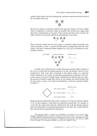
![2 Chapter 1 Introduction to Inorganic Chemistry
Organic Inorganic Organometallic
0
I ,cO
,I,
OC-Mn- CH,
FIGURE 1-1 Single and Multiple Bonds in Organic and Inorganic Molecules
FIGURE 1-2 Examples of
Bonditig Interactions.
Some of the most striking differences between the chemistry of carbon and that of
many other elements are in coordination number and geometry. Although carbon is usu-
ally limited to a maximum coordination number of four (a maximum of four atoms
bonded to carbon, as in CH4), inorganic compounds having coordination numbers of
five, six, seven, and more are very common; the most common coordination geometry is
an octahedral arrangement around a central atom, as shown for [T~F~],- Figure 1-4.
in](https://image.slidesharecdn.com/39116938-130119020116-phpapp02/85/39116938-11-320.jpg)


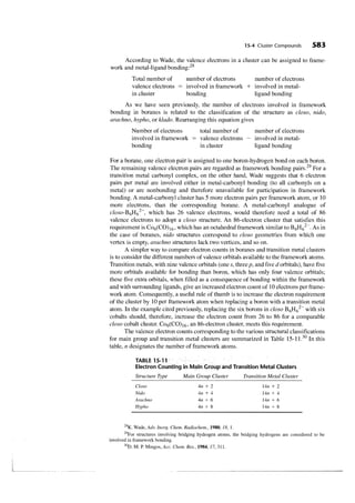
![1-5 Distribution of Elements on Earth 9
or more stable isotopes. 3 5 has a natural abundance of 75.77%, and 3 7 has a
~ ~ ~ ~
natural abundance of 24.23%. Both are stable, as are all the natural isotopes of the
lighter elements. The radioactive isotopes of these elements have short half-lives and
have had more than enough time to decay to more stable elements. 3 ~14C, and a few
,
other radioactive nuclei are continually being formed by cosmic rays and have a low
constant concentration.
Heavier elements ( Z = 40 or higher) may also have radioactive isotopes with
longer half-lives. As a result, some of these radioactive isotopes have not had time to
decay completely, and the natural substances are radioactive. Further discussion of iso-
topic abundances and radioactivity can be found in larger or more specialized ~ o u r c e s . ~
As atomic mass increases, the ratio of neutrons to protons in stable isotopes grad-
ually increases from 1 : 1 to 1.6 : 1 for 2@J. There is also a set of nuclear energy levels
similar to the electron energy levels described in Chapter 2 that result in stable nuclei
with 2, 8, 20, 28, 50, 82, and 126 protons or neutrons. In nature, the most stable nuclei
are those with the numbers of both protons and neutrons matching one of these num-
bers; $He, '$0, $ca, and ;q8pb are examples.
Elements not present in nature can be formed by bombardment of one element
with nuclei of another; if the atoms are carefully chosen and the energy is right, the two
nuclei can merge to form one nucleus and then eject a portion of the nucleus to form a
new element. This procedure has been used to extend the periodic table beyond uranium.
Neptunium and plutonium can be formed by addition of neutrons to uranium followed
by release of electrons (P particles). Still heavier elements require heavier projectiles
and higher energies. Using this approach, elements up to 112, temporarily called unun-
bium for its atomic number, have been synthesized. Synthesis of elements 114, 116, and
1 18 has been claimed, but the claim for 118 was later withdrawn. Calculations indicate
that there may be some relatively stable (half-lives longer than a few seconds) isotopes
of some of the superheavy elements, if the appropriate target isotopes and projectiles
are used. Suggestions include 2 4 8 ~ m ,5 0 ~ m , 2 4 4 as targets and 4 8 ~as the pro-
2 and ~ ~ a
jectile. Predictions such as this have fueled the search for still heavier elements, even
though their stability is so low that they must be detected within seconds of their cre-
ation before they decompose to lighter elements. Hoffman and ~ e have reviewed the
e ~
efforts to study the chemistry of these new elements. The subtitle of their article, "One
Atom at a Time," described the difficulty of such studies. In one case, a-daughter decay
chains of 2 6 5 ~ g
were detected from only three atoms during 5000 experiments, but this
was sufficient to show that Sg(V1) is similar to W(V1) and Mo(V1) in forming neutral or
negative species in HN03-HF solution, but not like U(VI), which forms [ U O ~ ] ~ ' under
these conditions. Element 108, hassium, formed by bombarding 2 4 8 ~ with high-ener-
m
gy atoms of 2 6 ~ g , found to form an oxide similar to that of osmium on the basis of
was
six oxide molecules carried from the reaction site to a detector by a stream of h e l i ~ m . ~
This may be the most massive atom on which "chemistry" has been performed to date.
1-5 Theories that attempt to explain the formation of the specific structures of the Earth
DISTRIBUTION OF are at least as numerous as those for the formation of the universe. Although the details
ELEMENTS ON of these theories differ, there is general agreement that the Earth was much hotter
EARTH during its early life, and that the materials fractionated into gaseous, liquid, and solid
states at that time. As the surface of the Earth cooled, the lighter materials in the crust
solidified and still float on a molten inner layer, according to the plate tectonics
3 ~ N. Greenwood and A. Earnshaw, Chemistry o the Elements, 2nd ed., Butterworth-Heinemann,
. f
Oxford, 1997; J. Silk, The Big Bang. The Creation and Evolution of the Universe, W. H . Freeman, San Fran-
cisco, 1980.
4 ~ C. Hoffman and D. M. Lee, J. Chem. Educ., 1999, 76,331.
.
hem. Eng. News, June 4,2001,p. 47.](https://image.slidesharecdn.com/39116938-130119020116-phpapp02/85/39116938-18-320.jpg)


![16 Chapter 2 Atomic Structure
When two measures of hydrogen and one of oxygen gas are mixed, and fired by the elec-
tric spark, the whole is converted into steam, and if the pressure be great, this steam be-
comes water. It is most probable then that there is the same number of particles in two
measures of hydrogen as in one of oxygen.3
In fact, he then changed his mind about the number of molecules in equal volumes of
different gases:
At the time I formed the theory of mixed gases, I had a confused idea, as many have, I sup-
pose, at this time, that the particles of elastic fluids are all of the same size; that a given vol-
ume of oxygenous gas contains just as many particles as the same volume of hydrogenous;
or if not, that we had no data from which the question could be solved. . . . I [later] became
convinced. . . That every species of pure elastic fluid has its particles globular and all of a
size; but that no two species agree in the size of their particles, the pressure and tempera-
ture being the same.4
Only a few years later, Avogadro used data from Gay-Lussac to argue that equal
volumes of gas at equal temperatures and pressures contain the same number of mole-
cules, but uncertainties about the nature of sulfur, phosphorus, arsenic, and mercury va-
pors delayed acceptance of this idea. Widespread confusion about atomic weights and
molecular formulas contributed to the delay; in 1861, Kekul6 gave 19 different possible
formulas for acetic acid!' In the 1850s, Cannizzaro revived the argument of Avogadro
and argued that everyone should use the same set of atomic weights rather than the
many different sets then being used. At a meeting in Karlsruhe in 1860, he distributed a
pamphlet describing his views.6 His proposal was eventually accepted, and a consistent
set of atomic weights and formulas gradually evolved. In 1869, ~ e n d e l e e v ~ ~ e ~ e r '
and
independently proposed periodic tables nearly like those used today, and from that time
the development of atomic theory progressed rapidly.
2-1-1 THE PERIODIC TABLE
The idea of arranging the elements into a periodic table had been considered by many
chemists, but either the data to support the idea were insufficient or the classification
schemes were incomplete. Mendeleev and Meyer organized the elements in order of
atomic weight and then identified families of elements with similar properties. By ar-
ranging these families in rows or columns, and by considering similarities in chemical
behavior as well as atomic weight, Mendeleev found vacancies in the table and was able
to predict the properties of several elements (gallium, scandium, germanium, polonium)
that had not yet been discovered. When his predictions proved accurate, the concept of
a periodic table was quickly established (see Figure 1-10). The discovery of additional
elements not known in Mendeleev's time and the synthesis of heavy elements have led
to the more complete modern periodic table, shown inside the front cover of this text.
In the modern periodic table, a horizontal row of elements is called a period, and
a vertical column is a group or family. The traditional designations of groups in the
United States differ from those used in Europe. The International Union of Pure and
Applied Chemistry (IUPAC) has recommended that the groups be numbered I through
18, a recommendation that has generated considerable controversy. In this text, we will
31bid.,p. 133
4~bid., 144-145.
pp.
5 ~ .Partington, A Short History of Chemistry, 3rd ed., Macmillan, London, 1957; reprinted, 1960,
~ .
Harper & Row, New York, p. 255.
6~bid., 256-258.
pp.
7 ~ I..Mendeleev, J. Russ. Phys. Chem. Soc., 1869, i, 60.
Meyer, Justus Liebigs Ann. Chem., 1870, Suppl, vii, 354.
8 ~ .](https://image.slidesharecdn.com/39116938-130119020116-phpapp02/85/39116938-25-320.jpg)


![2-2 The Schriidingel- Equation 27
TABLE 2-4
Hydrogen Atom Wave Functions: Radial Functions
Radial Functions R ( r ) , with 0 = Z r / a o
Orbital n 1 R(r)
The fourth quantum number explains several experimental observations. Two of
these observations are that lines in alkali metal emission spectra are doubled, and that a
beam of alkali metal atoms splits into two parts if it passes through a magnetic field.
Both of these can be explained by attributing a magnetic moment to the electron; it be-
haves like a tiny bar magnet. This is usually described as the spin of the electron be-
cause a spinning electrically charged particle also has a magnetic moment, but it should
not be taken as an accurate description; it is a purely quantum mechanical property.
The quantum number n is primarily responsible for determining the overall energy of
an atomic orbital; the other quantum numbers have smaller effects on the energy. The quan-
tum number I determines the angular momentum of the orbital or shape of the orbital and
has a smaller effect on the energy. The quantum number ml determines the orientation of the
angular momentum vector in a magnetic field, or the position of the orbital in space, as
shown in Table 2-3. The quantum number m, determines the orientation of the electron
1)
magnrlic moment in a magnetic field, either in the direction of the field ( + or opposed to
i).
it ( - When no field is present, all mi values (all threep orbitals or all five d orbitals) have
the same energy and both m, values have thc samc cncrgy. Togcthcr, the quantum numbers
n, 1, and ml define an atomic orbital; the quantum number m , describes the electron spin
within the orbital.
One feature that should be mentioned is the appearance of i (= fi) p in the
and d orbital wave equations in Table 2-3. Because it is much more convenient to work
with real functions than complex functions, we usually take advantage of another prop-
erty of the wave equation. For differential equations of this type, any linear combination
of solutions (sums or differences of the functions, with each multiplied by any coeffi-
cient) to the equation is also a solution to the equation. The combinations usually cho-
sen for the p orbitals are the sum and difference of the p orbitals having ml = 1 and +
1 i
- 1, normalized by multiplying by the constants -and -----,respectively:
./z
1
+
qZpx -----
=
fi
+ XI)=
'J3
-
2
- [ R ( r ) ] sin 0 cos
IT
- = - - [ R ( r ) ] 0 sin $
sin I](https://image.slidesharecdn.com/39116938-130119020116-phpapp02/85/39116938-36-320.jpg)


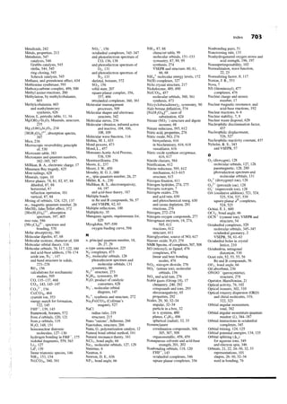
![TABLE 2-7
Electron Configurations of the Elements
Element Z Configuration Element Z Configuration
1s' Ce *[xe]6s24f 5d'
ls2 Pr [xe]6s24f"
Nd [ x e ] 6 s 2f4
[~e]2s'
[He]2s2 Pm [xe]6s24f"
[He]2s22p' Sm [xe]6s24f
[~e]2s~2p~ Eu [xe]6s24f
[~e]2s~2p' Gd * [ x e ] 6 s 2 4 f 5d'
[He]2s22p4 Tb [xe]6s24 f
[He]2s22p5 DY [xe]6s24fl o
[~e]2s'2p~ Ho [xe]6s24f "
Er [xe]6s24fl 2
[Ne]3s1
Tm [xe]6s24 l3 f
[~e]3s'
[Ne]3s23p' Yb [xe]6s24 l 4 f
[~e]3s~3p~ Lu [xe]6s24fI45d1
[Ne]3s23p3 Hf [xe]6s24fI45d2
[~e]3s~3p~ Ta [xe]6s24fI45d"
[Ne]3s23p5 W [xe]6s24f I45d4
[Ne]3s23p6 Re [xe]6s24f145d5
0s [xe]6s24fI45d6
[Ar]4s1 Ir [xe]6s24fI45d7
[Ar]4s2
Pt *[xe]6s14~I45d9
[Ar]4s23d'
Au * [ x e ] 6 s 1 4I45di0
f
[Ar]4s23d2
[~r]4s~3d' Hg [xe]6s24fI45di0
*[Ar]4si3d5 T1 [xe]6s24f'45d106p1
[Ar]4s23d5 Pb [xe]6s24f'45d'06p2
[Ar]4s23d6 Bi [xe]6s24f'45d106p"
[Ar]4s23d7 Po [xe]6s24 145d I06p4
f
[Ar14s23d8 At [xe]6s24fI45d I06p5
*[~r]4s'3d Rn [xe]6s24fI45dI06p6
[Ar]4s23d10
[Ar]4s23di04p' Fr
[Ar]4s23d104pL Ra
[Ar]4~~3d'~4p~ Ac
[Ar14s23dI04p4 Th
[Ar]4~~3d'~4p~ Pa
[Ar]4s23d"4p6 U
[Kr]5s1 NP
[Kr15s2 Pu
Am
[Kr]5s24d1 Cm
[~r]5s~4d~ Bk
*[Kr]5s'4d4 Cf
*[Kr]5s14d5 Es
[Kr]5s24d5 Fm
*[~r]5s'4d'
Md
*[Kr]5s'4d8
No
*[Kr]4d o
l
*[~r]5s'4d'~ Lr
[~r]5s~4d
[Kr]5~~4d'~5p' Rf
[Kr]5~~4d'~5p~ Db
[Kr]5s24d'?p3 sg
[Kr]5~~4d'~5p~ Bh
[~r]5s~4d'~5p~ Hs
[Kr]5~~4d'~5p~ Mt
[Xe]6s ' Uun
uuu
[xe]6s2
Uub
*[xe]6s25d1
* Elements with configurations that do not follow the simple order o f orbital filling.
NOTE: Actinide configurations are from J. J . Katz, G. T. Seaborg, and L. R. Morss, The Chemistry of the Actinide Elements, 2nd ed., Chapman and
Hall, New York and London, 1986. Configurations for elements 100 to 112 are predicted, not experimental.
39](https://image.slidesharecdn.com/39116938-130119020116-phpapp02/85/39116938-48-320.jpg)

![2-2 The SchrGdinger Equation 41
For the 4s electron,
z*=z-S
= 28 - [ l o X (1.00)] - [16 X (0.85)] - [ l X (0.35)] = 4.05
( I s , 2s, 2 p ) (3s, 3p, 3 4 (4s)
The ten Is, 2s, and 2 p electrons each contribute 1.00, the sixteen 3s, 3p, and 3d electrons each
contribute 0.85, and the other 4s electron contributes 0.35, for a total S = 23.95 and
Z* = 4.05, considerably smaller tha11 the value for the 3d electron above. The 4s electron is
held less tightly than the 3d and should therefore be the first removed in ionization. This is
consistent with experimental observations on nickel compounds. ~ i " , the most common oxi-
dation state of nickel, has an electron configuration of [ ~ r ] 3 d (rather than [ ~ r ] 3 d ~ 4 scor-,
' *)
responding to loss of the 4s electrons from nickel atoms. All the transition metals follow this
same pattern of losing ns electrons more readily than ( n - 1)d electrons.
EXERCISE 2-5
Calculate the effective nuclear charge on a 5s, a 5p, and a 4d electron in a tin atom.
EXERCISE 2-6
nuclear charge on a 7s, a 5f , and a 6d electron in a uranium atom.
Justification for Slater's rules (aside from the fact that they work) comes from the
electron probability curves for the orbitals. The s and p orbitals have higher probabili-
ties near the nucleus than do d orbitals of the same n, as shown earlier in Figure 2-7.
Therefore, the shielding of 3d electrons by (3s, 3 p ) electrons is calculated as 100%ef-
fective (a contribution of 1.00). At the same time, shielding of 3s or 3p electrons by
(2s, 2p) electrons is only 85% effective (a contribution of0.85), because the 3s and 3p
orbitals have regions of significant probability close to the nucleus. Therefore, electrons
in these orbitals are not completely shielded by (2s, 2p) electrons.
A complication arises at Cr ( 2 = 24) and Cu ( 2 = 29) in the first transition se-
ries and in an increasing number of atoms under them in the second and third transition
series. This effect places an extra electron in the 3d level and removes one electron from
the 4s level. Cr, for example, has a configuration of [ ~ r ] 4 s l 3 d ~
(rather than [ ~ r ] 4 s ~ 3 d ~ ) .
Traditionally, this phenomenon has often been explained as a consequence of the "spe-
cial stability of half-filled subshells." Half-filled and filled d and f subshells are, in fact,
fairly common, as shown in Figure 2-1 1. A more accurate explanation considers both
the effects of increasing nuclear charge on the energies of the 4s and 3d levels and the
interactions (repulsions) between the electrons sharing the same orbital.25 This ap-
proach requires totaling the energies of all the electrons with their interactions; results
of the complete calculations match the experimental results.
Another explanation that is more pictorial and considers the electron-electron in-
teractions was proposed by ~ i c hHe explained the structure of these atoms by specif-
. ~ ~
ically considering the difference in energy between the energy of one electron in an
orbital and two electrons in the same orbital. Although the orbital itself is usually as-
sumed to have only one energy, the electrostatic repulsion of the two electrons in one
orbital adds the electron pairing energy described previously as part of Hund's rule. We
can visualize two parallel energy levels, each with electrons of only one spin, separated
by the electron pairing energy, as shown in Figure 2-1 2. As the nuclear charge increas-
es, the electrons are more strongly attracted and the energy levels decrease in energy,
becoming more stable, with the d orbitals changing more rapidly than the s orbitals
because the d orbitals are not shielded as well from the nucleus. Electrons fill the
"L. G. Vanquickenborne, K. Pierloot, and D. Devoghel, J. Chem. Educ., 1994,71,469.
2 6 ~ L.
.Rich, Periodic Correlations, W. A. Benjamin, Menlo Park, CA, 1965,pp. 9-1 1.](https://image.slidesharecdn.com/39116938-130119020116-phpapp02/85/39116938-50-320.jpg)


![. . .. . , ,. ,,~t.,.."...",
48 Chapter 2 Atomic Structure
2-3 The transition from the n = 7 to the n = 2 level of the hydrogen atom is accompanied
by the emission of light slightly beyond the range of human perception, in the ultravio-
let region of the spectrum. Determine the energy and wavelength of this light.
2-4 The details of several steps in the particle in a box model in this chapter have been
omitted. Work out the details of the following steps:
+
a. Show that if P = A sin rx B cos sx (A, B, r, and s are constants) is a solution to
'
the wave equation for the one-dimensional box, then
b. Show that if ?V' = A sin rx, the boundary conditions (?V'
= 0 when x = 0 and
nT
7
x = a ) require that r = i--, where n = any integer other than zero.
a
nT
7
c. Show that if r = f-, the energy levels of the particle are given by
a
d. Show that substituting the above value of r into T = A sin rx and applying the nor-
malizing requirement gives A = m.
2-5 For the 3p, and 4d,, hydrogen-like atomic orbitals, sketch the following:
a. The radial function R.
b. The radial probability function a o r 2 ~ ' .
c. Contour maps of electron density.
2-6 Repeat the exercise in Problem 5 for the 4s and 5dxLy2orbitals.
2-7 Repeat the exercise in Problem 5 for the 5s and 4dz2 orbitals.
2-8 The 4fZ(,Ly2) orbital has the angular function Y = (constant)z(x2 - y2).
a. How many spherical nodes does this orbital have?
b. How many angular nodes does it have?
c. Describe the angular nodal surfaces.
d. Sketch the shape of the orbital.
2-9 Repeat the exercise in Problem 8 for the 5fxyz orbital, which has Y = (constant)xyz.
2-10 a. Find the possible values for the I and rnl yuarltum numbers for a 5d elcctron, a 4f
electron, and a 7g electron.
b. Find the possible values for all four quantum numbers for a 3d electron.
2-11 Give explanations of the following phenomena:
a. The electron configuration of Cr is [ ~ r ] 4 s ' 3 drather than [ ~ r ] 4 s ~ 3 d ~ .
~
b. The electron configuration of Ti is [ ~ r ] 4 s * 3 dbut that of cr2+ is l ~ r l 3 d ~ .
~,
2-12 Give electron configurations for the following:
a. V b. Br c. R U ~ + d. H~~~ e. Sb
2-13 Which 2+ ion has five 3d electrons? Which one has two 3d electrons?
2-14 Determine the Coulombic and exchange energies for the following configurations and
determine which configuration is favored (of lower energy):
'T
a. --and -'T 'T & -
b. - Ta n d - - t -
t t.1 t
2-15 Using Slater's rules, determine Z* for
a. A 3p electron in P, S, C1, and Ar. Is the calculated value of Z* consistent with the
relative sizes of these atoms?
b. A 2 p electron in 0*-,F-, ~ a ' , and ~ g " . Is the calculated value of Z* consistent
with the relative sizes of these ions?](https://image.slidesharecdn.com/39116938-130119020116-phpapp02/85/39116938-57-320.jpg)
![Problems 49
c. A 4s and a 3d electron of Cu. Which type of electron is more likely to be lost when
copper forms a positive ion?
d. A 4f electron in Ce, Pr, and Nd. There is a decrease in size, commonly known as the
lanthanide contraction, with increasing atomic number in the lanthanides. Are
your values of Z* consistent with this trend?
Select the better choice in each of the following, and explain your selection briefly.
a. Higher ionization energy: Ca or Cia
b. Higher ionization energy: Mg or Ca
c. Higher electron affinity: Si or P
d. More likely configuration for ~ n ~ + : [ A r ] 4 ~ ~[ 3 r ]~ d '
or ~ d 3
Ionization energies should depend on the effective nuclear charge that holds the elec-
trons in the atom. Calculate Z* (Slater's rules) for N, P, and As. Do their ionization en-
ergies seem to match these effective nuclear charges? If not, what other factors
influence the ionization energies?
The ionization energies for C1-, C1, and e l f are 349, 1251, and 2300 kJ/mol, respec-
tively. Explain this trend.
-
The second ionization of carbon (c'
(B +
-
Why are the ionization energies of the alkali metals in the order Li > Na > K
+
B+ e+) both fit the reaction 1 ~ ~ 2 =~ls22s2 + e-. Compare the two
~ 2 ~ '
> Rb?
c2+ e-) and the first ionization of boron
ionization energies (24.383 eV and 8.298 eV, respectively) and the effective nuclear
charges, Z*. Is this an adequate explanation of the difference in ionization energies? If
not, suggest other factors.
In each of the following pairs, pick the element with the higher ionization energy and
explain your choice.
a. Fe,Ru b . P , S c . K , B r d . C , N e . C d , I n
On the basis of electron configurations, explain why
a. Sulfur has a lower electron affinity than chlorine.
b. Iodine has a lower electron affinity than bromine.
c. Boron has a lower ionization energy than beryllium.
d. Sulfur has a lower ionization energy than phosphorus
e. Chlorine has a lower ionization energy than fluorine.
a. The graph of ionization energy versus atomic number for the elements Na through
Ar (Figure 2-13) shows maxima at Mg and P and minima at A1 and S. Explain these
maxima and minima.
b. The graph of electron affinity vs. atomic number for the elements Na through Ar
(Figure 2-13) also shows maxima and minima, but shifted one element in comparison
with the ionization energy graph. Why are the maxima and minima shifted in this way?
The second ionization energy of He is almost exactly four times the ionization energy
of H, and the third ionization energy of Li is almost exactly nine times the ionization
energy of H:
IE (MJ mol-')
Explain this trend on the basis of the Bohr equation for energy levels of single-
electron systems.
2-25 The size of the transition metal atoms decreases slightly from left to right in the period-
ic table. What factors must be considered in explaining this decrease? In particular, why
does the size decrease at all, and why is the decrease so gradual?](https://image.slidesharecdn.com/39116938-130119020116-phpapp02/85/39116938-58-320.jpg)
![50 Chapter 2 Atomic Structure
2-26 Predict the largest and smallest in each series:
2-27 Prepare a diagram such as the one in Figure 2-12(a) for the fifth period in the periodic
table, elements Zr through Pd. The configurations in Table 2-7 can be used to determine
the crossover points of the lines. Can a diagram be drawn that is completely consistent
with the configurations in the table?
2-28 There are a number of websites that display atomic orbitals. Use a search engine to find
a. A complete set of the f orbitals.
b. A complete set of the g orbitals.
Include the URL for the site wjth each of these, along with sketches or printouts of the
orbitals. [One website that allows display of any orbital, complete with rotation and
scaling, is h~~p://www.orbital.com/.]](https://image.slidesharecdn.com/39116938-130119020116-phpapp02/85/39116938-59-320.jpg)


. There are rarely
]~ ~
more than 18 electrons (2 for s, 6 for p, and 10 for d orbitals) around a single atom in the
top half of the periodic table, and crowding of the outer atoms usually keeps the number
below this, even for the much heavier atoms with f orbitals energetically available.
3-1-3 FORMAL CHARGE
Formal charges can be used to help in the assessment of resonance structures and mole-
cular topology. The use of formal charges is presented here as a simplified method of
describing structures, just as the Bohr atom is a simple method of describing electronic
configurations in atoms. Both of these methods are incomplete and newer approaches
are more accurate, but they can be useful as long as their limitations are kept in mind.
Formal charges can help in assigning bonding when there are several possibilities.
This can eliminate the least likely forms when we are considering resonance structures
and, in some cases, suggests multiple bonds beyond those required by the octet rule. It
is essential, however, to remember that formal charge is only a tool for assessing Lewis
structures, not a measure of any actual charge on the atoms.
Formal charge is the apparent electronic charge of each atom in a molecule, based
on the electron-dot structure. The number of valence electrons available in a free atom
of an element minus the total for that atom in the molecule (determined by counting
lone pairs as two electrons and bonding pairs as one assigned to each atom) is the for-
mal charge on the atom:
number of valence
Formal charge =
atom of the element
number of unshared
electrons on the atom - inumber of bonds
to the atom
In addition,
Charge on the molecule or ion = sum of all the formal charges
'L. Suidan, J. K. Badenhoop, 35. D. Glcndening, and F. Weinhold, J. Chem. Educ., 1995, 72, 583;
J. Cioslowski and S. T. Mixon, Inorg. Chem., 1993,32,3209; E. Magnusson, J. Am. Chem. Soc., 1990, 112,
7940.](https://image.slidesharecdn.com/39116938-130119020116-phpapp02/85/39116938-63-320.jpg)


![3-2 Valence Shell Electron Pair Repulsion Theory 59
FIGURE 3-9 Conversion of a
Cube into a Square Antiprism.
the center of the plane. The regular square antiprism structure (SN = 8) is like a cube
with the top and bottom faces twisted 45" into the antiprism arrangement, as shown in
Figure 3-9. It has three different bond angles for adjacent fluorines. [ T ~ F has] ~ ~~
square antiprism symmetry, but is distorted from this ideal in the solid.7 (A simple cube
has only the 109.5' and 70.5" bond angles measured between two corners and the cen-
ter of the cube, because all edges are equal and any square face can be taken as the bot-
tom or top.)
3-2-1 LONE PAIR REPULSION
We must keep in mind that we are always attempting to match our explanations to ex-
perimental data. The explanation that fits the data best should be the current favorite,
but new theories are continually being suggested and tested. Because we are working
with such a wide variety of atoms and molecular structures, it is unlikely that a single,
simple approach will work for all of them. Although the fundamental ideas of atomic
and molecular structures are relatively simple, their application to complex molecules is
not. It is also helpful to keep in mind that for many purposes, prediction of exact bond
H
I angles is not usually required. To a first approximation, lone pairs, single bonds, double
H-C-H bonds, and triple bonds can all be treated similarly when predicting molecular shapes.
I However, better predictions of overall shapes can be made by considering some impor-
H
tant differences between lone pairs and bonding pairs. These methods are sufficient to
show the trends and explain the bonding, as in explaining why the H -N -H angle in
H-N-H ammonia is smaller than the tetrahedral angle in methane and larger than the
H- 0 -H angle in water.
H
Steric number = 4
H-0:
The isoelectronic molecules CH4, NH3, and H 2 0 (Figure 3-10) illustrate the effect of
H lone pairs on molecular shape. Methane has four identical bonds between carbon and
each of the hydrogens. When the four pairs of electrons are arranged as far from each
FIGURE 3-10 Shapes of Methane, other as possible, the result is the familiar tetrahedral shape. The tetrahedron, with all
Ammonia, and Water. H- C -H angles measuring 109.S0,has four identical bonds.
7 ~ L.
. Hoard, W. J. Martin, M. E. Smith, and J. F. Whitney, J. Am. Chern. Soc., 1954, 76, 3820.](https://image.slidesharecdn.com/39116938-130119020116-phpapp02/85/39116938-69-320.jpg)


![Problems 73
G E N E R A L Good sources for bond lengths and bond angles are the references by Wells, Greenwood
REFERENCES and Earnshaw, and Cotton and Wilkinson cited in Chapter 1. Appendix D provides a re-
view of electron-dot diagrams and formal charges at the level of most general chemistry
texts. Alternative approaches to these topics are available in most general chemistry
texts, as are descriptions of VSEPR theory. One of the best VSEPR references is still the
early paper by R. J. Gillespie and R. S. Nyholm, Q. Rev. Chem. Soc. 1957, XI, 339-380.
More recent expositions of the theory are in R. J. Gillespie and I. Hargittai, The VSEPR
Model ofMolecular Geometry, Allyn & Bacon, Boston, 1991, and R. J. Gillespie and P.
L. A. Popelier, Chemical Bonding and Molecular Geometry: From Lewis to Electron
Densities, Oxford University Press, New York, 2001. Molecular orbital arguments for
the shapes of many of the same molecules are presented in B. M. Gimarc, Molecular
Structure and Bonding, Academic Press, New York, 1979, and J. K. Burdett, Molecular
Shapes, John Wiley & Sons, New York, 1980.
PROBLEMS 3-1 The dimethyldithiocarbamate ion, [S2CN(CH&-, has the following skeletal structure:
a. Give the important resonance structures of this ion, including any formal charges
where necessary. Select the resonance structure likely to provide the best descrip-
tion of this ion.
b. Repeat for dimethylthiocarbamate, [OSCN(CH3)2]-.
Several resonance structures are possible for each of the following ions. For each, draw
these resonance structures, assign formal charges, and select the resonance structure
likely to provide the best description for the ion.
a. Selenocyanate ion, SeCN-
b. Thioformate ion, H -C '
S
c. Dithiocarbonate, [s2c012- (C is central)
Draw the resonance structures for the isoelectronic ions NSO- and SNO-, and assign
formal charges. Which ion is likely to be more stable?
Three isomers having the formula N2C0 are known: ONCN (nitrosyl cyanide), ONNC
(nitrosyl isocyanide), and NOCN (isonitrosyl cyanide). Draw the most important reso-
nance structures of these isomers, and determine the formal charges. Which isomer do
you predict to be the most stable (lowest energy) form? (Reference: G. Maier, H. P.
Reinsenauer, J. Eckwert, M. Naumann, and M. De Marco, Angew. Chern., Int. Ed.,
1997, 36, 1707.)
Predict and sketch the structure of the (as yet) hypothetical ion IF^^^.
Select from each set the molecule or ion having the smallest bond angle, and briefly ex-
plain your choice:
a. NH3, pH3, or AsH3
b. 03+, 0 3 , or 03-
halogen angle)](https://image.slidesharecdn.com/39116938-130119020116-phpapp02/85/39116938-83-320.jpg)

![Problems 75
c. Predict the structure of CAI4. (Reference: X. Li, L-S. Wang, A. I. Boldyrev, and
J. Simons, J. Am. Chern. Soc., 1999,121,6033.)
For each of the following bonds, indicate which atom is more negative. Then rank the
series in order of polarity.
a. C-N b. N-0 c. C-I d. 0-C1 e. P-Br f. S-Cl
Explain the following:
a. PC15 is a stable molecule, but NC15 is not.
b. SF4 and SF6 are known, but OF4 and OF6 are not.
Provide explanations for the following:
a. Methanol, CH30H, has a much higher boiling point than methyl mercaptan, CH3SH.
b. Carbon monoxide has slightly higher melting and boiling points than N2.
c. The ortho isomer of hydroxybenzoic acid [C6H4(0H)(C02H)] has a much lower
melting point than the meta and para isomers.
d. The boiling points of the noble gases increase with atomic number.
e. Acetic acid in the gas phase has a significantly lower pressure (approaching a limit
of one half) than predicted by the ideal gas law.
f. Mixtures of acetone and cl~loroformexhibit significant negative deviations from
Raoult's law (which states that the vapor pressure of a volatile liquid is proportional
to its mole fraction). For example, an equimolar mixture of acetone and chloroform
has a lower vapor pressure than either of the pure liquids.
L. C. Allen has suggested that a more meaningful formal charge can be obtained by tak-
ing into account the ele~trone~ativities the atoms involved. Allen's formula for this
of
type of charge, referred to as the Lewis-Langmuir (L-L) charge, of an atom, A, bonded
to another atom, B, is
(US) group - number of unshared - number of bonds
L-L charge =
number of A electrons on A
where XA and XB designate the electronegativities. Using this equation, calculate the
L-L charges for CO, NOp, and HF and compare the results with the corresponding for-
mal charges. Do you think the L-L charges are a better representation of electron distri-
bution? (Reference: L. C. Allen, J. Am. Chern. Soc., 1989,111,9115.)
Predict the structure of I(CF3)C12. Do you expect the CF3 group to be in an axial or
equatorial position? Why? (Reference: R. Minkwitz and M. Merkei, Inorg. Chern.,
1999,38,5041.)
Two ions isoelectronic with carbon suboxide, C3O2, are N ~ and OCNCO+. Whereas
+
C3O2 is linear, both N ~ ' and OCNCO' arc bcnt at thc ccntral nitrogen. Suggcst an
explanation. Also predict which has the smaller outer atom-N-outer atom angle
and explain your reasoning. (References: I. Bernhardi, T. Drews, and K. Seppelt,
Angew. Chem., Int. Ed., 1999,38,2232; K. 0 . Christe, W. W. Wilson, J. A. Sheehy, and
J. A. Boatz, Angew. Chem., Int. Ed., 1999,38,2004.)
The thiazyl dichloride ion, NSC12-, has recently been reported. This ion is
isoelectronic with thionyl dichloride, OSC12.
a. Which of these species has the smaller C1- S -C1 angle? Explain briefly.
b. Which do you predict to have the longer S-C1 bond? Why? (Reference: E.
Kessenich, F. Kopp, P. Mayer, and A. Schulz, Angew. Chern.,Int. Ed., 2001,40, 1904.)
Although the C -F distances and the F-C -F bond angles differ considerably in
F2C=CF2, F2C0, CF4, and F3CO- (C-F distances: 131.9 to 139.2 pm; F-C -F
bond angles: 101.3" to 109S0), the F . . . F distance in all four structures is very nearly
the same (215 to 218 pm). Explain, using the LCP model of Gillespie. (Reference: R. J.
Gillespie, Coord. Chem. Rev., 2000,197, 5 1.)](https://image.slidesharecdn.com/39116938-130119020116-phpapp02/85/39116938-85-320.jpg)


![86 Chapter 4 Symmetry and Group Theory
HC1 has C,, symmetry, C 0 2 has DWh symmetry, CH4 has tetrahedral ( T d )
symmetry, SF6 has octahedral (Oh) symmetry, and B ~ ~ has icosahedral- ( I h )
H ~ ~ ~
symmetry
There are now seven molecules left to be assigned to point groups out of the
original 15.
4-2-2 OTHER CROUPS
2. Find the rotation axis with the highest n, the highest order C, axis for the
molecule. This is the principal axis of the molecule.
The rotation axes for the examples are shown in Figure 4-9. If they are all equiv-
alent, any one can be chosen as the principal axis.
PF5 H,CCH, 1,3,5,7-tetrafluoro- C3 perpendicular to
cyclooctatetraene the plane of the page
Ko(en),13+
C2 perpendicular to the
plane of the molecule
FIGURE 4-9 Rotation Axes.
3. Does the molecule have any C2 axes perpendicular to the C, axis?
The C2 axes are shown in Figiire, 4-10.
ii
FIGURE 4-10 Perpendicular C2 PF5 H,CCH, ~~ocen)~]~
Axes. Yes Yes Yes](https://image.slidesharecdn.com/39116938-130119020116-phpapp02/85/39116938-96-320.jpg)


![90 Chapter 4 Symmetry and Group Theory
TABLE 4-B--cont'd
Further Examples of C and D Pdnt Crdkps
General Label Point Group and Example
Dhh benzene
acetylene (CzH2) H-CsC-H
Ddd Ni(c~c1obutadiene)~
(staggered)
D3 [R~(NH~CH~CH~NH~)~]~'
(treating the NH2CH2CH2NH2
group as a planar ring)
'"J
Determine the point groups of the following molecules and ions from Figures 3-13 and 3-16:
XeF4 is not in the groups of low or high symmetry.
Its highest order rotation axis is C4.
It has four C2 axes perpendicular to the C4 axis and is therefore in the D set of groups.
It has a horizontal plane perpendicular to the C4 axis. Therefore its point group is D4h.
It is not in the groups of high or low symmetry.
Its highest order (and only) rotation axis is a C2 axis passing through the lone pair.
The ion has no other C2 axes and is therefore in the C or S set.
It has no minor plane perpendicular to the C2.
It has two minor planes containing the C2 axis. Therefore, the point group is Cb.
The molecule has no symmetry (other than E). Its point group is C1.
I EXERCISE 4-3
I Use the procedure described above to verify the point groups of the molecules in Table 4-4.](https://image.slidesharecdn.com/39116938-130119020116-phpapp02/85/39116938-100-320.jpg)

![FIGURE 4-13 W[N(CH3)2]6,
a Molecule with Th Symmetry.
Th symmetry is rare but is known for a few molecules. The compound shown in
Figure 4- 13 is an example. I, 0,and T symmetry are rarely if ever encountered in chernislry.
That's all there is to it! It takes a fair amount of practice, preferably using molec-
ular models, to learn the point groups well, but once you know them, they can be ex-
tremely useful. Several practical applications of point groups appear later in this
chapter, and additional applications are included in later chapters.
4-3 All mathematical groups (of which point groups are special types) must have certain
PROPERTIES AND properties. These properties are listed and illustrated in Table 4-6, using the symmetry
REPRESENTATIONS operations of NH3 in Figure 4-14 as an example.
OF CROUPS
4-3-1 MATRICES
Important information about the symmetry aspects of point groups is summarized in
character tables, described later in this chapter. To understand the construction and use
of character tables, we first need to consider Lhe properties of matrices, which are the
basis for the tables2
C3 rotation about the z axis One of the mirror planes
FIGURE 4-14 Symmetry Opera-
tions for Ammonia. (Top view) NH3
is of point group C3v,with the sym- /
N N N
metry operations E, C j , c j 2 , a,, H2 H3 H< H< 'H~
a' a,", usually written as E, 2C3,
,,
and 3a, (note that c~~ E ) .
= NH3 after E NH3 after C3 NH3 after o (.yz)
,
2 ~ o r details on matrices and their manipulation are available in Appendix I of F. A. Cotton,
e
Chemical Applications ofGroup Theory, 3rd ed., John Wiley & Sons, New York. 1990, and in linear algebra
and finite mathematics textbooks.](https://image.slidesharecdn.com/39116938-130119020116-phpapp02/85/39116938-102-320.jpg)

![94 Chapter 4 Symmetry and Croup Theory
I
This example has 2 rows and 2 columns in each initial matrix, so it has 2 rows and 2 columns
in the product matrix; i = j = k = 2.
I Here, i = 1, j = 3, and k = 3, so the product matrix has 1 row (i) and 3 columns ( j ) .
I Here i = 3, j
EXERCISE 4-4
= 1, and k = 3, so the product matrix has 3 rows (i) and 1 column ( j ) .
Do the following multiplications:
4-3-2 REPRESENTATIONS OF POINT GROUPS
Symmetry operations: Matrix
representations
Consider the effects of the symmetry operations of the C2, point group on the set of x,
y, and z coordinates. [The set o f p orbitals (p,, py, pZ) behaves the same way, so this is
a useful exercise.] The water molecule is an example of a molecule having C2, symme-
try. It has a C2 axis through the oxygen and in the plane of the molecule, no perpendic-
ular C2 axes, and no horizontal mirror plane, but it does have two vertical mirror planes,](https://image.slidesharecdn.com/39116938-130119020116-phpapp02/85/39116938-104-320.jpg)
![4-3 Properties and Representations of Groups 95
G x
/ /O /O /O
HI H2 H2 HI HI '32 '32 HI
FIGURE 4-15 Symmetry Opera-
tions uT Lhe Water Molecule. Coordinate system After C2 ATlcr o,(xz) After o,'(yz)
as shown in Table 4- 1 and Figure 4- 15. The z axis is usually chosen as the axis of high-
est rotational symmetry; for HzO, this is the only rotational axis. The other axes are ar-
bitrary. We will use the xz plane as the plane of the m ~ l e c u l eThis set of axes is chosen
.~
to obey the right-hand rule (the thumb and first two fingers of the right hand, held per-
pendicular to each other, are labeled x,y, and z,respectively).
Each symmetry operation may be expressed as a transformation matrix as follows:
[New coordinates] = [transformation matrix][old coordinates]
As examples, consider how transformation matrices can be used to represent the sym-
metry operations of the C2, point group:
C2: Rotate a point having coordinates (x, y, z) about the Cz(z) axis. The new coordi-
nates are given by
XI = newx = -x
y1 = newy = -y ( 0 - 1 0 ( transformation matrix for C2
z1 = new z = z
In matrix notation.
transformation new coordinates
in terms of old I
u,(xz): Reflect a point with coordinates (x, z) through the xz plane.
y,
x'
yt
newx = x
=
= new y = -y
z1 = new z = z
[k -% 81 transformation matrix for cr(xz~
The matrix equation is
3 ~ o m sources use yz as the plane of the molecule. The assignment of B, and B2 in Section 4-3-3 is
e
reversed with this choice.](https://image.slidesharecdn.com/39116938-130119020116-phpapp02/85/39116938-105-320.jpg)

![4-3 Properties and Representations of Croups 97
When matrices are block diagonalized in this way, the x, y, and z coordinates are
also block diagonalized. As a result, the x, y, and z coordinates are independent of each
other. The matrix elements in the 1,l positions (numbered as row, column) describe the
results of the symmetry operations on the x coordinate, those in the 2,2 positions de-
scribe the results of the operations on they coordinate, and those in the 3,3 positions de-
scribe the results of the operations on the z coordinate. The four matrix elements for x
form a representation of the group, those for y form a second representation, and those
for z form a third representation, all shown in the following table:
Irreducible representations E Cz u,(xz) u~'(Yz) Coordinate Used
of the C2, point group, 1 -1 1 -1 x
which add to make up the / 1 -1 -1 1 / Y
reducible representation r 1 I 1 1 z
r 3 -1 1 1
Each row is an irreducible representation (it cannot be simplified further), and the
characters of these three irreducible representations added together under each opera-
tion (column) make up the characters of the reducible representation T,just as the com-
bination of all the matrices for the x, y, and z coordinates makes up the matrices of the
reducible representation. For example, the sum of the three characters for x, y, and z
under the C2 operation is -1, the character for r under this same operation.
The set of 3 X 3 matrices obtained for H 2 0 is called a reducible representation,
because it is the sum of irreducible representations (the block diagonalized 1 X 1 ma-
trices), which cannot be reduced to smaller component parts. The set of characters of
these matrices also forms the reducible representation T,for the same reason.
4-3-3 CHARACTER TABLES
Three of the representations for C22,,labeled A l , B 1 , and B2 below, have been deter-
mined so far. The fourth, called A2, can be found by using the properties of a group de-
scribed in Table 4-7. A complete set of irreducible representations for a point group is
called the character table for that group. The character table for each point group is
unique; character tables for the common point groups are included in Appendix C.
The complete character table for C2, with the irreducible representations in the
order commonly used, is
The labels used with character tables are as follows:
x, Y , z transformations of the x, y , z coordinates or combinations thereof
Rs, R,, R, rotation about the x, y, and z axes
R any symmetry operation [such as C2 or u,(xz)]
X character of an operation
i and j designation of different representations (such as A 1 or A?)
h order of the group (the total number of symmetry operations in the group)](https://image.slidesharecdn.com/39116938-130119020116-phpapp02/85/39116938-107-320.jpg)


![102 Chapter 4 Symmetry and Group Theory
b. Subscript 1 designates a representation symmetric to a C2 rotation perpendicu-
lar to the principal axis, and subscript 2 designates a representation antisym-
metric to the C2. If there are no perpendicular C2 axes, 1 designates a
representation symmetric to a vertical plane, and 2 designates a representation
antisymmetric to a vertical plane.
c. Subscript g (gerade) designates symmetric to inversion, and subscript u
(ungerade) designates antisymmetric to inversion.
d. Single primes are symmetric to o h and double primes are antisymmetric to o h
when a distinction between representations is needed (C3),, CSh,D3h, DSh).
4-4 4-4-1 CHIRALITY
EXAMPLES A N D
APPLICATIONS OF Many molecules are not superimposable on their mirror image. Such molecules, labeled
SYMMETRY chiral or dissymmetric, may have important chemical properties as a consequence of
this nonsuperimposability. An example of a chiral organic molecule is CBrCIFI, and
many examples of chiral objects can also be found on the macroscopic scale, as in
Figure 4-1 8.
Chiral objects are termed dissymmetric. This term does not imply that these ob-
jects necessarily have no symmetry. For example, the propellers shown in Figure 4-18
each have a C3 axis, yet they are nonsuperimposable (if both were spun in a clockwise
direction, they would move an airplane in opposite directions!). In general, we can say
that a molecule or some other object is chiral if it has no symmetry operations (other
than Q or if it has only proper rotation axes.
EXERCISE 4-6
Which point groups are possible for chiral molecules? (Hint: Refer as necessary to the charac-
ter tables in Appendix C.)
Air blowing past the stationary propellers in Figure 4-18 will be rotated in either
a clockwise or counterclockwise direction. By the same token, plane-polarized light
will be rotated on passing through chiral molecules (Figure 4-19); clockwise rotation is
designated dextrorotatory, and counterclockwise rotation levorotatory. The ability of
chiral molecules to rotate plane-polarized light is termed optical activity and may be
measured experimentally.
Many coordination compounds are chiral and thus exhibit optical activity if they
can be resolved into the two isomers. One of these is [ R U ( N H ~ C H ~ C H ~ N Hwith ] ~ + ,
~)~
F ' F
I I I
FIGURE 4-18 A Chiral Molecule
and Other Chiral Objects.](https://image.slidesharecdn.com/39116938-130119020116-phpapp02/85/39116938-112-320.jpg)


![4-4 Examples and Applications of Symmetry 105
Reducing representations to irreducible
representations
The next step is to separate this representation into its component irreducible represen-
tations. This requires another property of groups. The number of times that any irre-
ducible representation appears in a reducible representation is equal to the sum of the
products of the characters of the reducible and irreducible representations taken one
operation at a time, divided by the order of the group. This may be expressed in equa-
tion form, with the sum taken over all symmetry operations of the group.4
"umber of irreducible) =
representations of
Order
[( number
of operations
)( character of
reducible
)( character of
irreducible
)]
a given type in the class representation representation
In the water example, the order of CZv is 4, with one operation in each class
( E , C 2 ,u,", u,'). The results are then
The reducible representation for all motions of the water molecule is therefore
+
reduced to 3A1 A:! + 3B1 2B2. +
Examination of the columns on the far right in the character table shows that
translation along the x, y, and z directions is A I + +
B1 B2 (translation is motion along
the x, y, and z directions, so it transforms in the same way as the three axes) and that
+ +
rotation in the three directions (R,, Ry , R Z )is A2 B1 B2. Subtracting these from
+
the total above leaves 2A1 Bl , the three vibrational modes, as shown in Table 4-10.
The number of vibrational modes equals 3N - 6, as described earlier. Two of the
modes are totally symmetric ( A l )and do not change the symmetry of the molecule, but
one is antisymmetric to C2 rotation and to reflection perpendicular to the plane of the
molecule ( B , ) . These modes are illustrated as symmetric stretch, symmetric bend, and
antisymmetric stretch in Table 4-1 1.
4 ~ h i procedure should yield an integer for the number of irreducible representations of each type;
s
obtaining a fraction in this step indicates a calculation error.](https://image.slidesharecdn.com/39116938-130119020116-phpapp02/85/39116938-115-320.jpg)


![118 Chapter 5 Molecular Orbitals
Because the u molecular orbital is the sum of the two atomic orbitals,
1
-' [$(Is,) + $(l s ~ ) ]and results in an increased concentration of electrons between
,
6
the two nuclei where both atomic wave functions contribute, it is a bonding molecular
orbital and has a lower energy than the starting atomic orbilals. The u* molecular
1
orbital is the difference of the two atomic orbitals, ----[+(ls,) - +(lsb)]. It has a
di
node with zero electron density between the nuclei caused by cancellation of the two
wave functions and has a higher energy; it is therefore called an antibonding orbital.
Electrons in bonding orbitals are concentrated between the nuclei and attract the nuclei
and hold them together. Antibonding orbitals have one or more nodes between the nu-
clei; electrons in these orbitals cause a mutual repulsion between the atoms. The differ-
ence in energy between an antibonding orbital and the initial atomic orbitals is slightly
larger than the same difference between a bonding orbital and the initial atomic orbitals.
Nonbonding orbitals are also possible. The energy of a nonbonding orbital is essen-
tially that of an atomic orbital, either because the orbital on one atom has a symmetry
that does not match any orbitals on the other atom, or the energy of the molecular
orbital matches that of the atomic orbital by coincidence.
The u (sigma) notation indicates orbitals that are symmetric to rotation about the
line connecting the nuclei:
o" from s orbital o" from p, orbital
An asterisk is frequently used to indicate antibonding orbitals, the orbitals of higher .:
energy. Because the bonding, nonbonding, or antibonding nature of a molecular orbital
is sometimes uncertain, the asterisk notation will be used only in the simpler cases in
which the bonding and antibonding characters are clear.
The pattern described for H2 is the usual model for combining two orbitals: two
atomic orbitals combine to form two molecular orbitals, one bonding orbital with a
lower energy and one antibonding orbital with a higher energy. Regardless of the num- i
ber of orbitals, the unvarying rule is that the number of resulting molecular orbitals is :
i
the same as the initial number of atomic orbitals in the atoms.](https://image.slidesharecdn.com/39116938-130119020116-phpapp02/85/39116938-127-320.jpg)


![5-2 Homonuclear Diatomic Molecules 123
FIGURE 5-5 Molecular Orbitals
for the First 10 Elements, with no
a-aInteraction. a ...,-
og ,,ex
orbitals according to the same rules that govern the filling of atomic orbitals (filling
from lowest to highest energy [aufbau], maximum spin multiplicity consistent with the
lowest net energy [Hund's rules], and no two electrons with identical quantum numbers
[Pauli exclusion principle]).
The overall number of bonding and antibonding electrons determines the number
of bonds (bond order):
Bond order = -
number of electrons
in bonding orbitals > - (
number of electrons
in antibonding orbitals >1
For example, 02, with 10 electrons in bonding orbitals and 6 electrons in antibonding
orbitals, has a bond order of 2, a double bond. Counting only valence electrons (8 bond-
ing and 4 antibonding) gives the same result. Because the molecular orbitals derived
from the 1s orbitals have the same number of bonding and antibonding electrons, they
have no net effect on the bonding.
Additional labels are helpful in describing the orbitals and have been added to
Figure 5-5. We have added g and u subscripts, which are used as described at the end of](https://image.slidesharecdn.com/39116938-130119020116-phpapp02/85/39116938-132-320.jpg)


![126 Chapter 5 Molecular Orbitals
FIGURE 5-7 Energy Levels of
the Homonuclear Diatomics of the
Second Period.
Bond order Li2
1
Unpaired e- 0
"2 " 9
0 2
;
0 0
22 0 0
bond order of $, has been detected in low-pressure gas discharge systems. As expected,
it is less stable than H2 and has a considerably longer bond distance (106 pm) than H2
(74.2 pm).
He2 [U~'U,*~(I s)]
The molecular orbital description of He2 predicts two electrons in a bonding orbital and
two electrons in an antibonding orbital, with a bond order of zero-in other words, no
bond. This is what is observed experimentally. The noble gas He has no significant
tendency to form diatomic molecules and, like the other noble gases, exists in the form
of free atoms. He2 has been detected only in very low pressure and low temperature
molecular beams. It has a very low binding energy,3 approximately 0.01 J/mol; for
comparison, H2 has a bond energy of 436 kJ/mol.
3 ~ LUO, C. McBane, G.
. G. Kim, C. F. Giese, and W. R. Gentry, J. Chem. Phys., 1993,98,3564](https://image.slidesharecdn.com/39116938-130119020116-phpapp02/85/39116938-135-320.jpg)

![128 Chapter 5 Molecular Orbitals
N2 has a triple bond according to both the Lewis and the molecular orbital models. This
is in agreement with its very short N-N distance (109.8 pm) and extremely high bond
dissociation energy (942 kJ/mol). Atomic orbitals decrease in energy with increasing
nuclear charge Z as shown in Figure 5-7; as the effective nuclear charge increases, all
orbitals are pulled to lower energies. The shielding effect and electron-electron interac-
tions described in Section 2-2-4 cause an increase in the difference between the 2s and
2 p orbital energies as Z increases, from 5.7 eV for boron to 8.8 eV for carbon and
12.4 eV for nitrogen. (A table of these energies is given in Table 5-1 in Section 5-3-1.)
As a result, the a g ( 2 s ) and o g ( 2 p )levels of N2 interact (mix) less than the B2 and C2
levels, and the o g ( 2 p )and IT,(^^) are very close in energy. The order of energies of
these orbitals has been a matter of controversy and will be discussed in more detail in
Section 5-2-4 on photoelectron spectroscopy.6
0 2 is paramagnetic. This pToperty, as for B2, cannot be explained by the traditional
Lewis dot structure (:O=O:), but is evident from the MO picture, which assigns two
electrons to the degenerate vg* orbitals. The paramagnetism can be demonstrated by
pouring liqnid O2 between the poles of a strong magnet; some of the O2 will be held be-
tween the pole faces until it evaporates. Several ionic forms of diatomic oxygen are
known, including 02+, 02-, and oZ2-. internuclear 0 -0 distance can be conve-
The
niently correlated with the bond order predicted by the molecular orbital model, as
shown in the following table.
Internuclear
Bond Order Distance ( p m )
NOTE: Oxygen-oxygen distances in 0 2 - and 0 2 ~ - are influenced by the
cation. This influence is especially strong in the case of 02~- and is one
factor in its unusually long bond distance.
The extent of mixing is not sufficient in O2 to push the a g ( 2 p )orbital to higher
energy than the v g ( 2 p ) orbitals. The order of molecular orbitals shown is consistent
with the photoelectron spectrum discussed in Section 5-2-4.
FZ [ u g 2 ~ u 2 ~ u 2 ~ g * 2 ~ g * 2 ( 2 p ) ]
The MO picture of F2 shows a diamagnetic molecule having a single fluorine-fluorine
bond, in agreement with experimental data on this very reactive molecule,
The net bond order in N2, 0 2 , and F2 is the same whether or not mixing is taken into
account, but the order of the filled orbitals is different. The switching of the order of the
6 ~ the first and second editions of this text, the order of the ng and T , orbitals in N2 was reversed
n
from the order in Figurc 5-7. We have since become persuaded that the a, orbital has the higher energy.
7 ~ Herzberg, Molecular Spectra and Molecular Structure I: The Spectra of Diatomic Molecules, Van
.
Nostrand-Reinhold, New York, 1950, p. 366.
%. L. Miller and C. H. Townes, Phys. Rev., 1953,90,537.
9 ~ . - Vannerberg, Prog. Inorg. Chem., 1963,4, 125.
~ .](https://image.slidesharecdn.com/39116938-130119020116-phpapp02/85/39116938-137-320.jpg)


![148 Chapter 5 Molecular Orbitals
Molecular orbitals of nonlinear molecules can be determined by the same procedures.
Water will be used as an example, and the steps of the previous section will be used.
1. Water is a simple triatomic bent molecule with a C2 axis through the oxygen and
two mirror planes that intersect in this axis, as shown in Figure 5-27. The point
group is therefore C2,.
2. The C2 axis is chosen as the z axis and the xz plane as the plane of the molecule.21
Because the hydrogen 1s orbitals have no directionality, it is not necessary to as-
sign axes to the hydrogens.
3. Because the hydrogen atoms determine the symmetry of the molecule, we will
use their orbitals as a starting point. The characters for each operation for the Is
orbitals of the hydrogen atoms can be obtained easily. The sum or thc contribu-
tions to the character (I, 0, or - 1, as described previously) for each symmetry op-
eration is the character for that operation, and the complete list for all operations
of the group is the reducible representation for the atomic orbitals. The identity
operation leaves both hydrogen orbitals unchanged, with a character of 2.
FIGURE 5-27 Symmetry of the Twofold rotation interchanges the orbitals, so each contributes 0, for a total char-
Water Molecule.
acter of 0. Reflection in the plane of the molecule (a,) leaves both hydrogens un-
changed, for a character of 2; reflection perpendicular to the plane of the
molecule (a,') switches the two orbitals, for a character of 0, as in Table 5-2.
TABLE 5-2
&oms ,in Wker
Representations for Ch Symmetry Op,erationrfol ~ydrogen
Cz, Character Table
I:[ [: ];:[I
= for the identity operation
I:[ [y ]:b[]
= for the C2,, operation
[EL:] [b :][:,]
= for the G ,reflection (xz plane)
,
[;:I [y b][,:
= for the D,,'
reflection ( y z plane)
The reducible representation F = A 1 i BI :
-
2 1 ~ o msources use the yz plane as the plane of the molecule. This convention results in r
e = A, + B2
and switches the hl and b2 labels of the molecular orbitals.](https://image.slidesharecdn.com/39116938-130119020116-phpapp02/85/39116938-155-320.jpg)
![5-4 Molecular Orbitals for Larger Molecules 149
Hydrogen orbitals
1
Ha - Hb
Characters
A1
Ha + Hh
Charactcrs
Oxygen orbitals
PY B2
Characters
Px B1
Characters
om 1
00 o
-1 1
m 00
-1
Characters 1 1 1 1
FIGURE 5-28 Symmetry of
Atomic and Group Orbitals in the
Water Molecule. Characters 1 1 1 1
4. The representation can be reduced to the irreducible representations A + B 1 ,
r
representing the symmetries of the group orbitals. These group orbitals can now
be matched with orbitals of matching symmetries on oxygen. Both 2s and 2p,
orbitals have A1 symmetry, and the 2p, orbital has Bl symmetry. In finding
molecular orbitals, the first step is to combine the two hydrogen 1s orbitals.
1
The sum of the two, L [ T ( ~ a ) + T ( H b ) ] ,has symmetry A l and the difference,
1
v5
L[T(Ha) - T(Hb)], has symmetry B1, as can be seen by examining Figure
v5
5-28. These group orbitals, or symmetry-adapted linear combinations, are each
then treated as if they were atomic orbitals. In this case, the atomic orbitals are
identical and have equal coefficients, so they contribute equally to the group
1
orbitals. The normalizing factor is ---. In general, the normalizing factor for a
group orbital is v5
where ci = the coefficients on the atomic orbitals. Again, each group orbital is
treated as a single orbital in combining with the oxygen orbitals.
5. The same type of analysis can be applied to the oxygen orbitals. This requires
only the addition of -1 as a possible character when a p orbital changes sign.
Each orbital can be treated independently.](https://image.slidesharecdn.com/39116938-130119020116-phpapp02/85/39116938-156-320.jpg)
![150 Chapter 5 Molecular Orbitals
Molecular Oxygen Atomic Group Orbitals
Symmetry Orbitals Orbitals from Hydrogen Atoms Description
BI T6
-
- c9 NPX) + .lo [ $ ( H a ) - W b ) ] antibonding (clo is negative)
A1 9 5
-
- C7 $($I + cx [$(Hn) + *(Hb)l antibonding (c8 is negative)
-
B2 9 4 - ~(PY) nonbonding
A1 9 3
-
- c5 ~(Pz) + C6 [@(Ha) + d ~ ( ~ b ) l nearly nonbonding (slightly
bonding; c6 is very small)
B1 9 2
-
- C3 NPX) + C4 [$(Ha) - wb)l bonding (qis positive)
AI 9I -
- Ci C(s) + cz [$(Ha) + W b ) ] bonding (c2 is positive)
The s orbital is unchanged by all the operations, so it has A l symmetry.
The p, orbital has the B1 symmetry of the x axis.
The py orbital has the B2 symmetry of they axis.
The p, orbital has the Al symmetry of the z axis.
The x, y, and z variables and the more complex functions in the character tables
assist in assigning representations to the atomic orbitals.
6. The atomic and group orbitals with the same symmetry are combined into molec-
ular orbitals, as listed in Table 5-3 and shown in Figure 5-29. They are numbered
q, through q6 order of their energy, with 1 the lowest and 6 the highest.
in
The A , group orbital combines with the s and p, orbitals of the oxygen to form
three molecular orbitals: one bonding, one nearly nonbonding (slightly bonding), and
one antibonding (three atomic or group orbitals forming three molecular orbitals, q 1 ,
!P3, and q 5 ) . The oxygen p, has only minor contributions from the other orbitals in the
weakly bonding q3 orbital, and the oxygen s and the hydrogen group orbitals combine
weakly to form bonding and antibonding !PI and q5orbitals that are changed only
slightly from the atomic orbital energies.
The hydrogen B1 group orbital combines with the oxygen p, orbital to form two
MOs, one bonding and one antibonding ( Y 2 and !P6). The oxygen py ( q 4 , with B2
symmetry) does not have the same symmetry as any of the hydrogen 1s group orbitals,
and is a nonbonding orbital. Overall, there are two bonding orbitals, two nonbonding or
nearly nonbonding orbitals, and two antibonding orbitals. The oxygen 2s orbital is near-
ly 20 eV below the hydrogen orbitals in energy, so it has very little interaction with
them. The oxygen 2 p orbitals are a good match for the hydrogen 1s energy, allowing
formation of the bonding bl and a1 molecular orbitals.
When the eight valence electrons available are added, there are two pairs in bond-
ing orbitals and two pairs in nonbonding orbitals, which are equivalent to the two bonds
and two lone pairs of the Lewis electron-dot structure. The lone pairs are in molecular
orbitals, one b2 from the py of the oxygen, the other a l from a combination of s and p,
of the oxygen and the two hydrogen Is orbitals. The resulting molecular orbital diagram
is shown in Figure 5-29.
The molecular orbital picture differs from the common conception of the water
molecule as having two equivalent lone electron pairs and two equivalent 0 -H bonds.
In the MO picture, the highest energy electron pair is truly nonbonding, occupying the
2py orbital perpendicular to the plane of the molecule. The next two pairs are bonding .
:
pairs, .resulting from overlap of the 2p, and 2p, orbital with the 1s orbitals of the hy- j
drogens. The lowest energy pair is a lone pair in the essentially unchanged 2s orbital of j
the oxygen. Here, all four occupied molecular orbitals are different.](https://image.slidesharecdn.com/39116938-130119020116-phpapp02/85/39116938-157-320.jpg)


![160 Chapter 5 Molecular Orbitals
This means that the atomic orbitals in the hybrids must have the same symmetry prop-
erties as A1' and E'. More specifically, it means that one orbital must have the same symme-
try as Air (which is one-dimensional) and two orbitals must have the same symmetry,
collectively, as E' (which is two-dimensional). This means that we must select one orbital
with Al symmetry and one pair of orbitals that collectively have E' symmetry. Looking at the
functions listed for each in the right-hand column of the character table, we see that the s or-
bital (not libted, but understood to bc present for the totally symmetric representation) and the
d,2 orbitals match the A symmetry. However, the 3d orbitals, the lowest possible d orbitals,
are too high in energy for bonding in BF3 compared with the 2s and 2p. Therefore, the 2s or-
bital is the contributor, with Alr symmetry.
The functions listed for E' symmetry match the (p,, p,) set or the (dn2-yZ, d,,) set.
The d orbitals are too high in energy for effective bonding. so the 2px and 2py orbitals are used
by the central atom. A combination of one p orbital and one d orbital cannot be chosen be-
cause orbitals in parentheses must always be taken together.
Overall, the orbitals used in the hybridization are the 2s, 2p,, and 2p,, orbitals of boron,
comprising the familiar sp2 hybrids. The difference between this approach and the molecular
orbital approach is that these orbitals are combined to form the hybrids before considering
their interactions with the fluorine orbitals. Because the ovcrall symmetry is trigonal planar,
the resulting hybrids must have that same symmetry, so the three sp2 orbitals point at the three
comers of a planar triangle, and each interacts with a fluorine p orbital to form the three o
bonds. The energy level diagram is similar to the diagram in Figure 5-33, but the three u or-
bitals and the three a* orbitals each form degenerate sets. The 2p, orbital is not involved in
the bonding and serves as an acceptor in acld-base reactions.
EXERCISE 5-8
Determine the types of hybrid orbitals that are consistent with the symmetry of the central
atom in
b. [ P ~ C I ~ ] a - ,
~ square planar ion
The procedure just described for determining hybrids is very similar to that used in
finding the molecular orbitals. Hybridization uses vectors pointing toward the outlying
atoms and usually deals only with u bonding. Once the a hybrids are known, 71. bonding
is easily added. It is also possible to use hybridization techniques for IT bonding, but that
approach will not be discussed here.23Hybridization may be quicker than the molecular
orbital approach because the molecular orbital approach uses all the atomic orbitals of
the atoms and includes both a and 71. bonding directly. Both methods are useful and the
choice of method depends on the particular problem and personal preference.
EXERCISE 5-9
Find the reducible representation for all the u bonds, reduce it to its irreducible representa-
tions, and deteminc the sulfur orbitals used in bonding for SOC12.
2 3 ~A. Cotton, Chrrnical Applications o Group Theory, 3rd ed., John Wiley & Sons, New York, 1990,
. f
pp. 227-230.](https://image.slidesharecdn.com/39116938-130119020116-phpapp02/85/39116938-167-320.jpg)


![6-2 Major Acid-Base Concepts 173
FIGURE 6-5 HOMO-LUMO In-
teractions. (Adapted with permission
from W. B. Jensen, The Lewis Acid-
Base Concepts, Wiley-Interscience,
N e w York, 1980. ~ i g u r 4-6, p. 140
e
~ ~ ~~0 ~ Ca ~ ~ l ~ ~ :
Copyright O 1980, John Wiley &
Sons, Inc. Reprinted by permission (Reference
of John wile; & sons,-&.) Compound)
Reactant A is taken as a reference; water is a good example. The first combination
of reactants, A + B, has all the B orbitals at a much higher energy than those of water
(Ca, for example; the alkali metals react similarly but have only one electron in their
highest s orbital). The energies are so different that no adduct can form, but a transfer of
electrons can take place from B to A. From simple electron transfer, we might expect
formation of HzOP, but reduction of water yields hydrogen gas instead. As a result,
-
water is reduced to H2 and OH-, Ca is oxidized to ca2+:
2 H20 + Ca ca2+ + 2 OH- + H2 (water as oxidant)
If orbitals with matching shapes have similar energies, the resulting bonding
orbitals will have lower energy than the reactant HOMOs, and a net decrease in energy
(stabilization of electrons in the new HOMOs) results. An adduct is formed, with its sta-
bility dependent on the difference between the total energy of the product and the total
energy of the reactants.
An example with water as acceptor (with lower energy orbitals) is the reaction
n H20 -
with chloride ion (C in Figure 6-5):
+ C1- [C1(H20),]- (water as acid)
In this reaction, water is the acceptor, and the LUMO used is an antibonding or-
bital centered primarily on the hydrogen atoms (the chloride HOMO is one of its lone
pairs from a 3 p orbital).
A reactant with orbitals lower in energy than those of water (for example, M ~ ~ + ,
D in Figure 6-5) allows water to act as a donor:
6 H20 +M ~ + [ M ~ ( H ~ o ) ~ ] ~(water as base)
~ + +
Here, water is the donor, contributing a lone pair primarily from the HOMO, which has
a large contribution from the p, orbital on the oxygen atom (the magnesium ion LUMO
is the vacant 3s orbital). The molecular orbital levels that result from reactions with B or
C are similar to those in Figures 6-7 and 6-8 for hydrogen bonding.](https://image.slidesharecdn.com/39116938-130119020116-phpapp02/85/39116938-178-320.jpg)


![178 Chapter 6 Acid-Base and Donor-Acceptor Chemistry
bonding between other atoms. The description above can be described as a three-center
four-electron model,14 which results in a bond angle at the hydrogen within 10" to 15"
of a linear 180" angle.
6-2-7 ELECTRONIC SPECTRA (INCLUDING
CHARGE TRANSFER)
One reaction that shows the effect of adduct formation dramatically is the reaction of I2
as an acid with different solvents and ions that act as bases. The changes in spectra and
visible color caused by changes in electronic energy levels (shown in Figures 6-9 and
6-10) are striking. The upper molecular orbitals of I2 are shown on the left in
Figure 6-9, with a net single bond due to the filled 9ug orbital and lone pairs in the 4n,
*
and 4vg orbitals. In the gas phase, I2 is violet, absorbing light near 500 nm because of
promotion of an electron from the IT^ * level to the 9u, * level (shown in Figure 6-9).
This absorption removes the middle yellow, green, and blue parts of the visible spec-
trum, leaving red and violet at opposite ends of the spectrum to combine in the violet
color that is seen.
In nondonor solvents such as hexane, the iodine color remains essentially the
same violet, but in benzene and other IT-electron solvents it becomes more red-violet,
and in good donors such as ethers, alcohols, and amines the color becomes distinctly
brown. The solubility of I2 also increases with increasing donor character of the solvent.
-
Interaction of the donor orbital of the solvent with the 9u,* orbital results in a lower oc-
cupied bonding orbital and a higher unoccupied antibonding orbital. As a result, the
* +
a,* transition for I2 donor (Lewis base) has a higher energy and an ab-
ng
sorbance peak shifted toward the blue. The transmitted color shifts toward brown (com-
bined red, yellow, and green), as more of the yellow and green light passes through.
Water is also a donor, but not a very good one; 12 is only slightly soluble in water, and
the solution is yellow-brown. Adding I- (a very good donor) results in the formation of
-
13-, which is brown and, being ionic, is very soluble in water. When the interaction be-
tween the donor and I2 is strong, the LUMO of the adduct has a higher energy and the
energy of the donor-acceptor transition IT^
* a,*) increases.
-
In addition to these shifts, a new charge-transfer band appears at the edge of the
ultraviolet (230-400 nm, marked CT in Figure 6-10). This band is due to the transition
o a*, between the two new orbitals formed by the interaction. Because the u or-
bital has a larger proportion of the donor (solvent or I-) orbital and the a * orbital has a
larger proportion of the I2 orbital, the transition transfers an electron from an orbital that
is primarily of donor composition to one that is primarily of acceptor composition;
hence, the name charge transfer for this transition. The energy of this transition is less
predictable because it depends on the energy of the donor orbital. The transition may be
shown schematically as
The charge-transfer phenomenon also appears in many other adducts. If the -::
charge-transfer transition actually transfers the electron permanently, the result is an
oxidation-reduction reaction-the donor is oxidized and the acceptor is reduced. The
sequence of reactions of [ F ~ ( H ~ o ) ~ ] ~ +
(the acid) and aquated halide ions (the bases) "
:
1 4 ~ .L. DeKock and W. B. Bosma, J. Chem. Educ., 1988,65, 194. g](https://image.slidesharecdn.com/39116938-130119020116-phpapp02/85/39116938-183-320.jpg)
![6-3 Hard and Soft Acids and Bases 179
,'
,-
A
-
A
,
Donor-acceptor
1 transition 1
Charge transfer
transition
FIGURE 6-9 Electronic Transi-
tions in 12 Adducts. I2 Adduct Donor
forming [ F ~ ( H ~ o ) ~ x illustrates the whole range of possibilities as the energy of the
]~'
HOMO of the halide ion increases from F- to I-. All of them show charge-transfer
transitions. In concentrated iodide, there is complete transfer of the electron through
the reaction 2 ~ e +~2 I- --+ 2 ~ e +~12.+
+
6-3 In addition to their intrinsic strength, acids and bases have other properties that determine
HARD A N D SOFT the extent of reaction. For example, silver halides have a range of solubilities in aqueous
ACIDS A N D BASES solution. A simple series shows the trend:
AgF(s) + H 2 0 +~ ~ ' ( a q+ F-(aq)
) K,, = 205
Solvation of the ions -is certainly a factor in these reactions, with fluoride ion being
much more strongly solvated than the other anions. However, the trend is also related to
changes in the degree of interaction between the halides and the silver ions. The inter-
actions can be expressed in terms of hard and soft acids and bases (HSAB), in which](https://image.slidesharecdn.com/39116938-130119020116-phpapp02/85/39116938-184-320.jpg)


![184 Chapter 6 Acid-Base and Donor-Acceptor Chemistry
TABLE 6-4
SaR
~ a r d k n d Acids
Hard Acids Borderline Acids Soft Acids
H', ~ i +Na+, K+
,
~ e ~~ + " , ca2+, s r 2
g ,
BF3, B C k , K O & B(CH3)3 BH3, TI+, Tl(CH&
A13+,A1(CH3)3,AlCl;, A1H3
cr3+,~ n * +Fe3+, co3+
, Fe2+, co2+, Ni2+, CU*', zn2+ Cu+, A$, AU+,cd2+,HgZ2+,
Rh3+, 1r3+,Ru3+, 0s'' Hg2+, C H ~ H ~ '[co(cN)~]~-,
.
pd2+,pt2+, pt4+,
Ions with oxidation states of Br2, 1,
4 or higher
Metals with zero oxidation state
HX (hydrogen-bonding a acceptors: e.g., Vinitrobenzene,
molecules) quinones, tetracyanoethyleiie
-
Adapted from R. G. Pearson, J. Chenz. Educ., 1968,45,581.
SOURCE:
The trends in bases are even easier to see, with fluoride hard and iodide soft.
Again, more electrons and larger size lead to softer behavior. In another example, s2-is
softer than 0'- because it has more electrons spread over a slightly larger volume, mak-
ing s2-more polarizable. Within a group, such comparisons are easy; as the electronic
structure and size change, comparisons become more difficult but are still possible.
Thus, s2-is softer than C1-, which has the same electronic structure, because s2-has a
smaller nuclear charge and a slightly larger size. As a result, the negative charge is more
available for polarization. Soft acids tend to react with soft bases and hard acids with
hard bases, so the reactions produce hard-hard and soft-soft combinations. Quantitative
measures of hard-soft parameters are described in Section 6-3-2.
1s OH- or s'- more likely to form insoluble salts with 3+ transition metal ions? Which is
more likely to form insoluble salts with 2+ transition metal ions?
Because OH- is hard and S2- is soft, OH- is more likely to form insoluble salts with
3+ transition metal ions (hard) and s2 is more likely to form insoluble salts with 2+ transi-
tion metal ions (borderline or soft).
I EXERCISE 6-4
Some of the products of the following reactions will be insoluble and some form solublc
adducts. Consider only the HSAB characteristics in your answers.
a. Will CU'' react more strongly with OH- or NH3? With 0'- or s'-?
b. Will Fe3+ react more strongly with OH- or NH3? With 0'- or s2-?
c. Will Agi react more strongly with NH3 or pH3?
d. Will Fe, Fe2+, or ~ e react more strongly with CO?
~ +
More detailed comparisons are possible, but another factor, called the inherent
acid-base strength, must also be kept in mind in these comparisons. An acid or a base
may be either hard or soft and at the same time be either strong or weak. The strength of
the acid or base may be more important than the hard-soft characteristics; both must be
considered at the same time. If two soft bases are in competition for the same acid, the
one with more inherent base strength may be favored unless there is considerable dif-
ference in softness. As an example, consider the following reaction. Two hard-soft](https://image.slidesharecdn.com/39116938-130119020116-phpapp02/85/39116938-189-320.jpg)

![186 Chapter 6 Acid-Base and Donor-Acceptor Chemistry
I Group 2 is made up of borderline and soft acids that are readily precipitated in acidic
H2S solution, in which the s*-concentration is very low because the equilibrium
lies far to the left in acid solution. The metal ions in this group are soft enough that a low con-
centration of the soft sulfide is sufficient to precipitate them. Group 3 cleans up the remaining
transition metals in the list, all of which are borderline acids. In the basic H2S solution, the
equilibrium above lies far to the right and the high sulfide ion concentration precipitates even
these cations. A I ~ and cr3+ are hard enough that they prefer OH over s*- and precipitate as
-
hydroxides. Another hard acid could be ~ e ~ but it is reduced by s2-, and iron precipitates as
',
FeS. Group 4 is a clear-cut case of hard-hard interactions, and Group 5 cations are larger, with
only a single electronic charge, and thus have small electrostatic attractions for anions. For
this reason, they do not precipitate except with certain highly specific reagents, such as per-
chlorate, C104-, for potassium and tetraphenylborate, [B(C6Hs)4]-, or zinc uranyl acetate,
[Zn(U02)3(CzH302)9]-,for sodium.
This quick summary of the analysis scheme shows where hard-hard or soft-soft
combinations lead to insoluble salts, but also shows that the rules have limitations.
Some cations considered hard will precipitate under the same conditions as others that
are clearly soft. For this reason, any solubility predictions based on HSAB must be con-
sidered tentative, and solvent and other interactions must be considered carefully.
HSAB arguments such as these explain the formation of some metallic ores de-
scribed in Chapter 1 (soft and borderline metal ions form sulfide ores, hard metal ions
form oxide ores, some ores such as bauxite result from the leaching away of soluble
salts) and some of the reactions of ligands with metals (borderline acid cations of Co,
Ni, Cu, and Zn tend to form -NCS complexes, whereas softer acid cations of Rh, Ir,
Pd, Pt, Au, and Hg tend to form -SCN complexes). Few of these cases involve only
this one factor, but it is important in explaining trends in many reactions. There are ex-
amples of both -SCN and -NCS bonding with the same metal (Section 9-3-7),
along with compounds in which both types of bonding are found, with the thiocyanate
bridging between two metal atoms.
A somewhat oversimplified way to look at the hard-soft question considers the
hard-hard interactions as simple electrostatic interactions, with the LUMO of the
acid far above the HOMO of the base and relatively little change in orbital energies
on adduct formation.I8 A soft-soft interaction involves HOMO and LUMO energies
that are much closer and give a large change in orbital energies on adduct formation.
Diagrams of such interactions are shown in Figure 6-12, but they need to be used
with caution. The small drop in energy in the hard-hard case that seems to indicate
only small interactions is not necessarily the entire story. The hard-hard interaction
depends on a longer range electrostatic force, and this interaction can be quite
strong. Many comparisons of hard-hard and soft-soft interactions indicate that the
hard-hard combination is stronger and is the primary driving force for the reaction.
The contrast between the hard-hard product and the hard-soft reactants in such cases
provides the net energy difference that leads to the products. One should also re-
member that many reactions to which the HSAB approach is applied involve compe-
tition between two different conjugate acid-base pairs; only in a limited numbcr of
cases is one interaction large enough to overwhelm the others and deter~nine whether
the reaction will proceed.
".Tensen, pp. 262-265; C. K. Jergensen, Struct. Bonding (Berlin), 1966,1,234.](https://image.slidesharecdn.com/39116938-130119020116-phpapp02/85/39116938-191-320.jpg)


![190 Chapter 6 Acid-Base and Donor-Acceptor Chemistry
TABLE 6-7
I& EA, Cg,and 4 Values (kcal/mol)
:
Acid
Trimethylhoron, B(CH3)?
Boron trifluoride (gas), BF3
Trimethylaluminum, Al(CH&
Iodine (standard), I2
Trimethylgallium, Ga(CH&
Iodine monochloride, 1C1
Sulfur dioxide, SO2
Phenol, C6H50H
tert-hutyl alcohol, C4H90H
Pyrrole, C&NH
Chloroform, CHC13
Base CB EB
1-Azahicyclo[2.2.2] octane,
HC(C2H4)3N(qninuclidine) 13.2 0.704
Trimethylamine, (CH3)3N 115 4 0.808
Triethylamine, (C2H&N 11.09 0.991
Dimethylamine. (CH3)2NH 8.73 1.09
Diethyl sulfide, (C2H5)$ 7.40" 0.399
Pyridine, C5H5N 6.40 1.17
Methylamine, CH3NH2 5.88 1.30
Ammonia, NH3 3.46 1.36
Diethyl ether, (C2H=J20 3.25 0.963
N,N-dimethylacetamide, (CH3)2NCOCH3 2.58 1.32"
Benzene, C& 0.681 0.525
- - - -
SOURCE Data from R. S. Drago, J Chem. Educ ,1974,51,300
NOTE:* Reference values
tendency to form covalent bonds. The subscripts refer to values assigned to the acid and
base, with I2 chosen as the reference acid and N,N-dimethylacetamide and diethyl
sulfide as reference bases. The defined values (in units of kcal/mol) are
CA EA CB EB
I2 1.00 1.oo
N,N-dimethylacetamide 1.32
Diethyl sulfide 7.40
Values of EA and C A for selected acids and EB and CBfor selected bases are given f
in Table 6-7, and a longer list is in Appendix B-6. Combining the values of these para-
meters for acid-base pairs gives the enthalpy of reaction in kcal/mol; multiplying by
4.184 J/cal converts to joules (although we use joules in this book, these numbers were
originally derived for calories and we have chosen to leave them unchanged).
Examination of the data shows that most acids have lower CA values and higher 1
EA values than 12. Because I2 has no permanent dipole, it has little electrostatic attrac-
tion for bases and has a low E A . On the other hand, it has a strong tendency to bond i
with some other bases, indicated by a relatively large CA. Because 1.00 was chosen as I
the reference value for both parameters for 12, most CA values are below 1 and most EA
values are above 1. For CB and E B , this relationship is reversed.](https://image.slidesharecdn.com/39116938-130119020116-phpapp02/85/39116938-195-320.jpg)


![6-4 Acid and Base Strength 193
6-4-2 THERMODYNAMIC MEASUREMENTS
The enthalpy change of some reactions can be measured directly, but for those that do
not go to completion (as is common in acid-base reactions), thermodynamic data from
reactions that do go to completion can be combined using Hess's law to obtain the need-
ed data. For example, the enthalpy and entropy of ionization of a weak acid, HA, can be
found by measuring (1) the enthalpy of reaction of HA with NaOH, (2) the enthalpy of
reaction of a strong acid (such as HCl) with NaOH, and (3) the equilibrium constant for
dissociation of the acid (usually determined from the titration curve).
Enthalpy Change
(1) HA + OH- - +
- A + H20 AH,"
(2) +
H ~ O + OH- - +
- 2 H20 AH2"
From the usual thermodynamic relationships,
[because Reaction (3) = Reaction (1) - Reaction (2)]
Rearranging (6):
Naturally, the final calculation can be more complex than this when HA is already
partly dissociated in the first reaction, but the approach remains the same. It is also pos-
sible to measure the equilibrium constant at different temperatures and use Equation (6)
to calculate AH0 and AS". On a plot of In K , versus 1/T, the slope is -AH3"/R and
the intercept is AS3"/R. This method works as long as AH0 and AS0 do not change
appreciably over the temperature range used. This is sometimes a difficult condition.
Data for AH", AS", and K , for acetic acid are given in Table 6-9.
TABLE 6-9
Thermodynamics of Acetic Acid Dissociation
AHo (W mol-') AS0 (JK-' mol-')
H3O+ + OH- e 2 H20 -55.9 -80.4
HOAc + OH- eH20 + OAC -56.3 -12.0
HOAc ---' H+ + OAc
NOTE:A H o and ASo for these reactions change rapidly with temperature. Calculations based on these
data are valid only over the limited temperature range given above.](https://image.slidesharecdn.com/39116938-130119020116-phpapp02/85/39116938-198-320.jpg)


![198 Chapter 6 Acid-Base and Donor-Acceptor Chemistry
In less acidic (or more basic) solutions, hydroxide or oxide bridges between metal atoms
form, the high positive charge promotes more hydrogen ion dissociation, and a large ag-
gregate of hydrated metal hydroxide precipitates. A possible first step in this process is
In general, metal ions with larger charges and smaller radii are stronger acids. The
alkali metals show essentially no acidity, the alkaline earth metals show it only slightly,
2+ transition metal ions are weakly acidic, 3+ transition metal ions are moderately
acidic, and ions that would have charges of 4+ or higher as monatomic ions are such
strong acids in aqueous solutions that they exist only as oxygenated ions. Some exam-
ples of acid dissociation constants are given in Table 6-10.
TABLE 6-10
Hydrated Metal Ion Agdities
Metal Ion Ka Metal Ion Ka
~ e ~ + 6.7 X lo-' ~ e " 5 x
cr3+ 1.6 X cu2+ 5 x
A++ 1.1 x 5 x 10-10
SC'+ 1.1 x lo-5 zn2+ 2.5 X
NOTE:These are equilibrium constants for [M(H~o),]'" -tH 2 0 ; t
= [M(H~o),-~(oH)](~-')++ H ~ o + .
Solubility of the metal hydroxide is also a measure of cation acidity. The stronger
the cation acid, the less soluble the hydroxide. Generally, transition metal 3+ ions are
acidic enough to form hydroxides that precipitate even in the slightly acidic solutions
formed when their salts are dissolved in water. The yellow color of iron(II1) solutions
mentioned earlier is an example. A slight precipitate is also formed in concentrated so-
lutions unless acid is added. When acid is added, the precipitate dissolves and the color
disappears (Fe(II1) is very faintly violet in concentrated solutions, colorless in dilute so-
lutions). The 2+ d-block ions and M ~ precipitate as hydroxides in neutral or slightly
~ +
basic solutions, and the alkali and remaining alkaline earth ions are so weakly acidic
that no pH effects are measured. Some solubility products are given in Table 6-1 1.
, -
TABLE-6-11",
Satu'bility~ h d u c t 'onstiints
f ' . - ,
Metal Hydroxide K s ~ Metal Hydroxide Kv
WOW3 6 x WOW2 8 x lo-'"
Cr(OW3 7 x lo-" Cu(OW2 2.2 x
lo-2o
1.4 X loP34 Ni(OH)2 2 x lo-'"
zn(oH12 7 x
Mg(OH12 1.1 x lo-"
NOTE:These are equilibrium constants for the reaction M(OH),(s) ; Mn+(aq)
t + n OH-.
At the highly charged extreme, the free metal cation is no longer a detectable
species. Instead, ions such as permanganate (Mn04-), chromate ( c ~ o ~ ~ - uranyl
),
(uo~'), dioxovanadium (vo~'), and vanadyl ( ~ 0 " ) are formed, with oxidation](https://image.slidesharecdn.com/39116938-130119020116-phpapp02/85/39116938-203-320.jpg)


![204 Chapter 6 Acid-Base and Donor-Acceptor Chemistry
The Lewis superacids formed by the fluorides are a result of transfer of anions to
form complex fluoro anions:
2 HF + 2 SbF5 +
H ~ F + Sb2FII-
acid base acid base
acid base acid base
These acids are very strong Friedel-Crafts catalysts. For this purpose, the term su-
peracid applies to any acid stronger than AlC13, the most common Friedel-Crafts cata-
lyst. Other fluorides, such as those of arsenic, tantalum, niobium, and bismuth, also
form superacids. Many other compounds exhibit similar behavior; additions to the list
of superacids include HS03F-Nb(S03F)5and HS03F-Ta(S03F)5, synthesized by oxi-
dation of niobium and tantalum in HS03F by Their acidity is explained by
reactions similar to those for SbFSin fluorosulfonic acid. Crystal structures of a number
of the oxonium salts of Sb2F11- and cesium salts of several fluorosulfato ions have
more recently been determined,33 and AsF5 and SbF5 in HF have been used to protonate
H2Se, H3As, H3Sb, H2Se, H4P2, H202, and, ~ 2 .34 ~ 2
GENERAL W. B. Jensen, The Lewis Acid-Base Concepts: An Overview, Wiley-Interscience, New
REFERENCES York, 1980, and H. L Finston and Allen C. Rychtman, A New Hew of Current Acid-Base
Theories, John Wiley & Sons, New York, 1982, provide good overviews of the history
of acid-base theories and critical discussions of the different theories. R. G. Pearson's
Hard and Soft Acids and Bases, Dowden, Hutchinson, & Ross, Stroudsburg, PA, 1973,
is a review by one of the leading exponents of HSAB. For other viewpoints, the refer-
ences provided in this chapter should be consulted.
PROBLEMS Additional acid-base problems may be found at the end of Chapter 8.
6-1 For each of the following reactions identify the acid and the base. Also indicate which
--
acid-base definition (Lewis, solvent system, BrGnsted) applies. In some cases, more
than one definition may apply.
a. BF3 + 2 C1F [cI~F]+ + [BFJ
b. HC104 + CH3CN
c. PC15 + IC1 - CH~CNH' CI04-
[PC14]+ + [IC121-
+
e. 2 C103-
+
SO2 -
d. NOF ClF3 ---+[NO]+ + [CF4]-
+ 2 CIOz sod2- +
+
f. Pt XeF4 ---t PtF4 Xe
g. Xe03 OH- +
+
-
[HXe04]-
+
h. 2 HF SbF5 ---+[ H ~ F ~ +[SbF6Ip +
i. 2 NOCl
j. PtF5 C1F3+
+
- -
Sn +SnC12 + 2 NO (in N20J solvent)
[cIF~]' +
[PtF6]-
6-2
k. (ben~y1)~N CH3COOH
1. BH,- +8 OH-
+
-B(OH)4-
( b e n ~ ~ l +~ ~ ~ '
4 H20 +
) CH3COO-
Baking powder is a mixture of aluminum sulfate and sodium hydrogen carbonate, which
generates a gas and makes bubbles in biscuit dough. Explain what the reactions are.
Cicha and F. Aubke, J. Am. Chem. Soc., 1989,111,4328.
3 2 ~ V.
.
3 3 ~Zhang,
. S. J. Rettig, J. Trottcr, and F. Aubke, Inorg. Chem., 1996,35,6113.
3 4 ~ Minkwitz, A. Kormath, W. Sawodny, and J. Hahn, Inorg. Chem., 1996, 35, 3622, and
.
references therein.](https://image.slidesharecdn.com/39116938-130119020116-phpapp02/85/39116938-209-320.jpg)


![7-1 Formulas and Structures 209
cells and contribute to each. As can be seen in Figure 7-1, unit cells need not have
equal dimensions or angles. For example, triclinic crystals have three different angles
and may have three different distances for the dimensions of the unit cell.
The diagram below shows a space-filling diagram of a face-centered cubic unit cell cut to
show only the part of each atom that is inside the unit cell boundaries. The comer atoms are
each shared among eight unit cells, so of the atom is in the unit cell shown. The face-
4
centered atoms are shared between two unit cells, so of the atom is in the unit cell shown.
Thc eight corncrs of the unit cell then total 8 X = 1 atom, the six faces total 6 X $ - 3
atoms, and there is a total of 4 atoms in the unit cell.
EXERCISE 7-1
Calculate the number of atoms in each unit cell of
a. A body-centered cubic structure.
b. A hexagonal structure.
The structures are shown in Figure 7-1.
The positions of atoms are frequently described in lattice points, expressed as
fractions of the unit cell dimensions. For example, the body-centered cube has atoms at
the origin [x = 0, y = 0, z = 0, or (O,O, O)] and at the center of the cube [ x = i.
1 1
y = I . z = 3,or (i,4,$)I. The other atoms can be generated by moving these two
atoms in each direction in increments of one cell length.
Cubic
The most basic crystal structure is the simple cube, called the primitive cubic structure,
with atoms at the eight corners. It can be described by specifying the length of one side,
the angle 90°, and the single lattice point (0, 0, 0). Because each of the atoms is shared
between eight cubes, four in one layer and four in the layer above or below, the total
4
number of atoms in the unit cell is 8 X = 1, the number of lattice points required.
Each atom is surrounded by six others, for a coordination number (CN) of 6. This
structure is not efficiently packed because the spheres occupy only 52.4% of the total
volume. In the center of the cube is a vacant space that has eight nearest neighbors or a](https://image.slidesharecdn.com/39116938-130119020116-phpapp02/85/39116938-212-320.jpg)


![236 Chapter 7 The Crystalline Solid State
Hydrated montmorillonite has water between the silicate-aluminate-silicate layers.
The micas (e.g., muscovite) have potassium ions in comparable positions and also have
aluminum substituting for silicon in about 25% of the silicate sites. Changes in the pro-
portions of aluminum and silicon in either of these allow the introduction of other cations
and the formation of a large number of minerals. The layered structures of some micas is
very obvious, allowing them to be cleaved into sheets used for high-temperature applica-
tions in which a transparent window is needed. They also have valuable insulating prop-
erties and are used in electrical devices. If the octahedral ~ 1 is partially replaced by
~ '
M ~ ~ 'additional cations with charges of 1 t or 24- are also added to the structures, and
,
montmorillonites are the result. These clays have ion exchange properties, swell on the
absorption of water, and have thixotropic properties. They are gels when undisturbed
but become liquid when stirred, making them useful as oil field "muds7' and in paints.
Their formulas are variable, with Na0,33[(Mg0.33A11,67(OH)2(Si4010)].n ex- HzO as an
ample. The cations can include Mg, Al, and Fe in the framework and H, Na, K, Mg, or
Ca in the exchangeable positions.
The term asbestos is usually applied to a fibrous group of minerals, including the
amphiboles, such as tremolite, Ca2(OH)2Mg5(Si401 with double-chain structures,
and chrysotile, Mg3(0H)4Si205.In chrysotile, the dimensions of the silicate and mag-
nesium layers are different, resulting in a curling that forms the characteristic cylindri-
cal fibers.
The final group we will consider are the zeolites, mixed aluminosilicates contain-
ing (Si, Al),Oz, frameworks with cations added to maintain charge balance. These min-
erals contain cavities that are large enough for other molecules to enter. In fact, it is now
possible to make synthetic zeolites with cavities tailored for specific purposes. The
holes that provide entrances to the cavities can have from 4 to 12 silicon atoms around
them. A common feature of many of these is a cubo-octahedral cavity formed from 24
silicate tetrahedra, each sharing oxygens on three corners. These units can then be
linked by sharing of the external oxygen atoms to form cubic or tetrahedral units with
still larger cavities. These minerals exhibit ion exchange properties, in which alkali and
alkaline earth metal cations can exchange, depending on concentration. They were used
as water softeners to remove excess ca2+ and M ~ until + development of poly-
~ the
styrene ion exchange resins. They can also be used to absorb water, oil, and other mol-
ecules and are known in the laboratory as molecular sieves; a larger commercial market
is as cat litter and oil absorbent. They are also used in the petroleum industry as cata-
lysts and as supports for other surface catalysts. A large number of zeolites have been
described and illustrated in the Atlas qf Zeolite Structure The references by
Wells and Greenwood and Earnshaw, cited previously in this book, also provide more
information about these essential materials.
Figure 7-25 shows an example of the type of structure possible in the zeolites.
Others have larger or smaller pores and larger or smaller entries into the pores (from 4
to 12 Si -0 units are possible).
The extreme range of sizes for the pores (260 to 1120 pm) makes it possible to
control entry to and escape from the pores bascd on the size and branching geometry of
the added material. In addition, the surfaces of the pores can be prepared with reactive
metal atoms, providing opportunities for surface-catalyzed reactions. Although much of
the design of these catalytic zeolites is of the "try it and see what happens" style, pat-
terns are emerging from the extensive base of data and planned synthesis of catalysts is
possible in some cases.
I7w.M. Meier and D. H. Olson, Atlas ofzeolite Structure Types, 2nd ed., Structure Commission of
the International Zeolite Commission, Butterworths, London, 1988.](https://image.slidesharecdn.com/39116938-130119020116-phpapp02/85/39116938-239-320.jpg)


![8-3 Group 1 (IA): The Alkali Metals 251
The solutions of alkali metals are unstable and undergo slow decompositionto form amides:
Other metals-especially the alkaline earths Ca, Sr, and Ba and the lanthanides Eu and
Yb (both of which can form 2+ ions)--can also dissolve in liquid ammonia to give the
solvated electron; however, the alkali metals undergo this reaction more efficiently and
have been used far more extensively for synthetic purposes.
Alkali metal atoms have very low ionization energies and readily lose their outer-
most (nsl) electron to form their common ions of I + charge. These ions can form com-
plexes with a variety of Lewis bases (ligands, to be discussed more fully in Chapters 9
through 14). Of particular interest are cyclic Lewis bases that have several donor atoms
that can surround, or trap, cations. Examples of such molecules are shown in Fig-
ure 8-6. The first of these is one of a large group of cyclic ethers, commonly known as
"crown" ethers, which donate electron density to metals through their oxygen atoms. The
second, one of a family of cryptands (or cryptates), can be even more effective as a cage
with eight donor atoms surrounding a central metal. Metallacrowns, which incorporate
metals into the crown structure, have also been developed.7 An example of the frame-
work structure of an iron-containing metallacrown is also shown in Figure 8-6. The im-
portance of these structures is shown by the fact that D. J. Cram, C. J. Pedersen, and
J.-M. Lehn won the Nobel Prize in Chemistry in 1987 for work with these compounds.8
As might be expected, the ability of a cryptand to trap an alkali metal cation de-
pends on the sizes of both the cage and the metal ion: the better the match between these
sizes, the more effectively the ion can be trapped. This effect is shown graphically for
the alkali metal ions in Figure 8-7.
The largest of the alkali metal cations, CS', is trapped most effectively by the
largest cryptand ([3.2.2]), and the smallcst, ~ i ' , by the smallest cryptand ([2.1.11).~
Other conelations can easily be seen in Figure 8-6. Cryptands have played an important
role in the study of a characteristic of the alkali metals that was not recognized until
rather recently, a capacity to form negatively charged ions.
Although the alkali metals are known primarily for their formation of unipositive
ions. numerous examples of alkali metal anions (alkalides) have been reported since 1974.
18-crown-6 Cryptand [2.2.2]
or or
18C6 C222
: ,
' :
,
{
'.
i .
,
,.,
,
FIGURE 8-6 A Crown Ether, a Cryptand, a Metal Ion Encased in a Cryptand, and a Metallacrown.
1.
* '
7 ~ L. Pecoraro, A. J. Stemmler, B. R. Gibney, J. J. Bodwin, H. Wang, I. W. Kampf, and A. Barwinski,
.
"Metallacrowns: A New Class of Molecular Recognition Agents," in Progr: Inorg. Chenz., 1997, 45, 83-177.
cr heir Nobel Prize lectures: D. J. Cram, Angew. Chem., 1988, 100, 1041; C. J. Pedersen, Angew
Chem., 1988,100, 1053; J.-M. Lehn, Angew. Chem., 1988,100,91.
he numbers indicate the number of oxygen atoms in each bridge between the nitrogens. Thus,
cryptand [2.2.2] has one bridge with three oxygens and two bridges with two oxygens. as shown in Figure 8-7.](https://image.slidesharecdn.com/39116938-130119020116-phpapp02/85/39116938-252-320.jpg)


![254 Chapter 8 Chemistry of the Main Group Elements
. ,
TABLE 8-4
Properties of the Group 2 (1IA) Ekments: The Alkaline Earths
Ionization Electron Melting Boiling
Energy Afiniiy Point Point Electro-
Element (W r n o l l ) (W r n ~ l - ~ ) ' ("C) negativity
1287 2500~ 1.576
649 1105 1.293
839 1494 1.034
768 1381 0.963
727 1850~ 0.88 1
700b 1700b 0.9~
SOURCE: Table 8-3.
See
NOTES:a A q u e o solution,25' C.
~~
b~pproximate values.
Atoms of the Group 2 (IIA) elements are smaller than the neighboring Group 1
(IA) elements as a consequence of the greater nuclear charge of the former. The ob-
served result of this decrease in size is that the Group 2 elements are more dense and
have higher ionization energies than the Group 1 elements. They also have higher melt- ,.
ing and boiling points and higher enthalpies of fusion and vaporization, as can be seen
from Tables 8-3 and 8-4. Beryllium, the lightest of the alkaline earth metals, is widely
used in alloys with copper, nickel, and other metals. When added in small amounts to
copper, for example, beryllium increases the strength of the metal dramatically and im- r
proves the corrosion resistance while preserving high conductivity and other desirable
properties. Emeralds and aquamarine are obtained from two types of beryl, the mineral :
source of beryllium; the vivid green and blue colors of these stones are the result of i
small amounts of chromium and other impurities. Magnesium, with its alloys, is used t
widely as a strong, but very light, construction material; its density is less than one
fourth that of steel. The other alkaline earth metals are used occasionally, but in much i
smaller amounts, in alloys. Radium has been used in the treatment of cancerous tumors,
but its use has largely been superseded by other radioisotopes.
8-4-2 CHEMICAL PROPERTIES
The elements in Group 2 (IIA), with the exception of beryllium, have very similar chem-
ical properties, with much of their chemistry governed by their tendency to lose two
electrons to achieve a noble gas electron configuration. In general, therefore, elements in
this group are good reducing agents. Although not as violently reactive toward water as
the alkali metals, the alkaline earths react readily with acids to generate hydrogen:
The reducing ability of these elements increases with atomic number. As a conse-
quence, calcium and the heavier alkaline earths react directly with water in a reaction
that can conveniently generate small quantities of hydrogen:
Beryllium is distinctly different from the other alkaline earths in its chemical
properties. The smallest of the alkaline earths, it participates primarily in covalent
rather than ionic bonding. Although the ion [ B ~ ( H ~ o ) ~ ]known, free Be2+ ions are
is ~ +](https://image.slidesharecdn.com/39116938-130119020116-phpapp02/85/39116938-255-320.jpg)


![8-6 Group 14 (IVA) 261
/
B-N
Property Benzene Bornzine
Me1ting point ("C) 6 -57
Boiling point ("C) 80 55
Density (1) (g cm-3)a 0.81 0.81
Surface tension ( I ) (N m-')a 0.0310 0.0311
Dipole moment 0 0
Internuclear distance in ring (pm) 142 144
Internuclear distance, bonds to H (pm) C-H: 108 B-H: 120
N-H: 102
SOURCE: Data from N. N. Greenwood and A. Earnshaw, Chemistry of the Elenzem, Pergamon Press,
Elmsford, NY, 1984, p. 238.
NOTE:aAt the melting point.
Despite these parallels, the chemistry of these two compounds is quite different.
In borazine, the difference in electronegativity between boron (2.051) and nitrogen
(3.066) adds considerable polarity to the B-N bonds and makes the molecule much
more susceptible to attack by nucleophiles (at the more positive boron) and elec-
trophiles (at the more negative nitrogen) than benzene.
Parallels between benzene and isoelectronic inorganic rings remain of interest.
Some examples include reports on boraphosphabenzenes (containing B3P3 rings)19 and
[(CH3)A1N(2,6-diisopropylphenyl)]3containing an A13N3 ring.20
Another interesting parallel between boron-nitrogen chemistry and carbon chem-
istry is offered by boron nitride, BN. Like carbon (Section 8-6), boron nitride exists in a
diamond-like form and in a form similar to graphite. In the diamond-like (cubic) form,
each nitrogen is coordinated tetrahedrally by four borons and each boron by four nitro-
gens. As in diamond, such coordination gives high rigidity to the structure and makes
BN comparable to diamond in hardness. In the graphite-like hexagonal form, BN also
occurs in extended fused ring systems. However, there is much less delocalization of IT
electrons in this form and, unlike graphite, hexagonal BN is a poor conductor. As in the
case of diamond, the harder, more dense form (cubic) can be formed from the less dense
form (hexagonal) under high pressures.
8-6 8-6-1 THE ELEMENTS
CROUP 14 (IVA)
Elements in this group range from a nonmetal, carbon, to the metals tin and lead, with
the intervening elements showing semimetallic behavior. Carbon has been known from
prehistory as the charcoal resulting from partial combustion of organic matter. In
recorded history, diamonds have been prized as precious gems for thousands of years.
Neither form of carbon, however, was recognized as a chemical element until late in the
'%IH. P. P. Power, Angew. Chem.,Int. Ed., 1987,26,1270; J. Am. Chem. Soc., 1989,111,144.
V. R. Dias and
M. Waggoner, H. Hope, and P. P. Power, Angew. Chem., Int. Ed., 1988,27, 1699.
'OK.](https://image.slidesharecdn.com/39116938-130119020116-phpapp02/85/39116938-262-320.jpg)


![8-6 Group 14 (IVA) 267
FIGURE 8-17 Polymers of C(jO.(a) Rhombohedra1 polymer. (b) Ball-and-chain dimers. Top to
bottom, sp, closed-66 sp2, open-66 sp2, open-56 sp2, open-56 sp2 in a distorted configuration.
(c) Double 1 +
2 21 closed-66 isomer for C122.(d) Other linked and linear chains. The 56 and 66
labels indicate that the bonds are to carbons common to five- and six-membered rings and to two
six-membered rings, respectively. [(a) and (d) from M. Nufiez-Tegueiro, L. Marques, J. L. Hodeau.
0. Bethoux, and M. Penoux, Phys. Rev. Lett., 1995, 74,278; (b) and (c) from A. A. Shvartsburg,
R. R. Hudgins, R. Gutierrez, G. Jungnickel, T. Frauenheim, K. A. Jackson, and M. F. Jarrold,
J. Phys. Chem. A, 1999,103, 5275. Reproduced with permission.]
8-6-2COMPOUNDS
A common misconception is that carbon can, at most, be four-coordinate.Although carbon
is bonded to four or fewer atoms in the vast majority of its compounds, many examples are
now known in which carbon has coordination numbers of 5, 6, or higher. Five-coordinate
carbon is actually rather common, with methyl and other groups frequently forming
bridges between two metal atoms, as in A12(CH3)6 (see Figure 8-15). There is even
considerable evidence for the five-coordinate ion CH~'.~' Many organometallic cluster
compounds contain carbon atoms surrounded by polyhedra of metal atoms. Such com-
pounds, often designated carbide clusters, are discussed in Chapter 15. Examples of carbon
atoms having coordination numbers of 5 , 6 , 7 , and 8 are shown in Figure 8-18.
The two most familiar oxides of carbon, CO and C02, are colorless, odorless
gases. Carbon monoxide is a rarity of sorts, a stable compound in which carbon formal-
ly has only three bonds. It is extremely toxic, forming a bright red complex with the
iron in hemoglobin, which has a greater affinity for CO than for 0 2 . As described in
Chapter 5 , the highest occupied molecular orbital of CO is concentrated on carbon; this
provides the molecule an opportunity to interact strongly with a variety of metal atoms,
which in turn can donate electron density through thcir d orbitals to empty T* orbitals
(LUMOs) on CO. The details of such interactions will be described more fully in
Chapter 13.
3 8 ~ A.
. Olah and G. Rasul, Ace. Chem. Kes., 1997,;10,245.](https://image.slidesharecdn.com/39116938-130119020116-phpapp02/85/39116938-268-320.jpg)


![8-6 Croup 14 (IVA) 271
Silane, SiH4, is stable and, like methane, tetrahedral. However, although silanes
(of formula Si,,H,+2) up to eight silicon atoms in length have been synthesized, their
stability decreases markedly with chain length; Si2H6 (disilane) undergoes only very
slow decomposition, but Si8H18decomposes rapidly. In recent years, a few compounds
containing Si=Si bonds have been synthesized, but there is no promise of a chemistry
of multiply bonded Si species comparable at all in diversity with the chemistry of un-
saturated organic compounds. Germanes of formulas GeH4 to Ge5HI2have been made,
as have SnH4 (stannane), Sn2H6 and, possibly, PbH4 (plumbane), but the chemistry in
these cases is even more limited than of the silanes.
Why are the silanes and other analogous compounds less stable (more reactive)
than the corresponding hydrocarbons? First, the Si-Si bond is slightly weaker than
the C-C bond (approximate bond energies, 340 and 368 kJ mol-l, respectively), and
Si-H bonds are weaker than C-H bonds (393 versus 435 kJ mol-I). Silicon is less
electronegative (1.92) than hydrogen (2.30) and is, therefore, more susceptible to nucle-
ophilic attack (in contrast to carbon, which is more electronegative [2.54] than hydro-
gen). Silicon atoms are also larger and therefore provide greater surface area for attack
by nucleophiles. In addition, silicon atoms have low-lying d orbitals that can act as ac-
ceptors of electron pairs from nucleophiles. Similar arguments can be used to describe
the high reactivity of germanes, staunanes, and plumbanes. Silanes are believed to de-
compose by elimination of :SiH2 by way of a transition state having a bridging hydro-
gen, as shown in Figure 8-21. This reaction, incidentally, can be used to prepare silicon
of extremely high purity.
FIGURE 8 - 2 1 Decomposition of
Silanes.
As mentioned, elemental silicon has the diamond structure. Silicon carbide, Sic,
occurs in many crystalline forms, some based on the diamond structure and some on the
wurtzite structure (see Figures 7-6 and 7-8(b)). It can be made from the elements at high
temperature, Carborundum, one form of silicon carbide, is widely used as an abrasive,
with a hardness nearly as great as diamond and a low chemical reactivity. S i c has now
garnered interest as a high-temperature semiconductor.
The elements germanium, tin, and lead show increasing importance of the 2+
oxidation state, an example of the inert pair effect. For example, all three show two
sets of halides, of formula MX4 and MX2. For germanium, the most stable halides
have the formula GeX4; for lead, it is PbX2. For the dihalides, the metal exhibits a
stereochemically active lone pair. This leads to bent geometry for the free molecules
and to crystalline structures in which the lone pair is evident, as shown for SnC12 in
Figure 8-22.
Sn%
&kc,/ Sn,
kC1/
FIGURE 8 - 2 2 Structure of SnClz 80' c1 c1
in Gas and Crystalline Phases. Gas Crystalline](https://image.slidesharecdn.com/39116938-130119020116-phpapp02/85/39116938-272-320.jpg)
![272 Chapter 8 Chemistry of the Main Group Elements
8-7 Nitrogen is the most abundant component of the Earth's atmosphere (78.1% by
CROUP 15 (VA) volume). However, the element was not successfully isolated from air until 1772,
when Rutherford, Cavendish, and Scheele achieved the isolation nearly simultane-
ously by successively removing oxygen and carbon dioxide from air. Phosphorus was
first isolated from urine by H. Brandt in 1669. Because the element glowed in the
dark on exposure to air, it was named after the Greek phos, light, and phoros,
bringing. Tnterestingly, the last three elements in Group 15 (vA)~' had long been
isolated by the time nitrogen and phosphorus were discovered. Their dates of
discovery are lost in history, but all had been studied extensively, especially by
alchemists, by the 15th century.
These elements again span the range from nonmetallic (nitrogen and phosphorus)
to metallic (bismuth) behavior, with the elements in between (arsenic and antimony)
having intermediate properties. Selected physical properties are given in Table 8-9.
TABLE 8-9 , .
Properties of the ~ m u p (+A) Elements,
, , 15 , .
Ionization Electron Melting Boiling
Energy Afinity Point Point Electro-
Element (kJ mol -') (W mol-I) ("c1 ("c1 negativity
N 1402 -7 -210 - 195.8 3.066
P 1012 72 44a 280.5 2.053
b b 2.21 1
As 947 78
Sb 834 103 63 1 1587 1.984
Bi 703 91 27 1 1564 2.0IC
SOURCE: Table 8-3.
See
NOTES:alu-P4.
b~ublimes 615".
at
'Approximate value.
8-7-1 THE ELEMENTS
Nitrogen is a colorless diatomic gas. As discussed in Chapter 5, the dinitrogen molecule
has a nitrogen-nitrogen triple bond of unusual stability. In large part, the stability of this
bond is responsible for the low reactivity of this molecule (although it is by no means
totally inert). Nitrogen is therefore suitable as an inert environment for many chemical
studies of reactions that are either oxygen or moisture sensitive. Liquid nitrogen, at
77 K, is frequently used as a convenient, rather inexpensive coolant for studying low-
temperature reactions, trapping of solvent vapors, and cooling superconducting mag-
nets (actually, for preserving the liquid helium coolant, which boils at 4 K).
For more than a century, the only isolable chemical species containing nitrogen
and no other elements were N2 and the azide ion, N3-. Remarkably, in 1999, a third
such species, N5+, was reported, a product of the following reaction:
1+ N~+[ASF~]- not stable at room temperature but can be preserved for weeks at
is
.N. 78°C. The N5+ ion has a V-shaped structure, bent at the central nitrogen and linear at
N' '* N the neighboring atoms.41Furthermore, even though the ions c ~and 0 2 ~ - have been
~ -
.N6 N.
40~lements this group are sometimes called the pnicogens or pnictogens.
in
4 ' ~0.Clxiste, W. W. Wilson, J. A. Sheehy, and J. A. Boatz,Arzgew. Clzern., Int. Ed., 1999,38,2004; for
.
more information on nitrogen-containing species, see T. M. Klapotke, Angew. Chem., Int. Ed., 1999, 38, 2536.](https://image.slidesharecdn.com/39116938-130119020116-phpapp02/85/39116938-273-320.jpg)


![, ~ , . , - , ' , .
TABCE 8-10. . -
Cornpoundi and Ions ~ o n t a i n i , k~ o g e n an$
nr &yg&h :'
., ,
, ",
~. ,
.
.
, .
,
,
. ,. ,
Fomuh Name Structurea Notes
N20 Nitrous oxide mp = -90.9"C; bp = -88.5"C
N=N=O
NO Nitric oxide
115 mp = -163.6"C; bp = -151.8"C; bond order
N=O approximately 2.5; paramagnetic
No2 a Nitrogen dioxide Brown, paramagnetic gas; exists in equilibrium with
2x9
o+-N.+ N@,; 2 NO2 4 Nz04
L A 0
134"
N2°3 Dinitrogen trioxide 105" mp = -100.1"C; dissociates above melting point:
N203 G=== NO + NO2
N2°4 Dinitrogen tetroxide 0 0 mp = -11.Z0C; bp = -21.15"C; dissociates into
2 NO2 [AH(dissociation) = 57 kJ/mol]
0 0
N2°,5 Dinitrogen pentoxide N-0-N bond may be bent; consists of
0
N02+NO3- in the solid
,N-0-N
0 0
NO+ Nitrosonium or nitrosyl Isoelectronic with CO
lo6
N r 0
~ 0 2 ' Nitronium or nitryl Isoelectronic with C 0 2
115
O=N=O
NO2- Nitrite N-0 distance varies from 113 to 123 pm and bond
4N.h angle varies from 116" to 132' depending on
0 0
cation; versatile ligand (see Chapter 9)
NO3- Nitrate
0 Forms compounds with nearly all metals; as ligand,
has a variety of coordination modes
0
~ 2 0 ~ ~ - Hyponitrite Useful reducing agent
0
/
O/N=N
~ 0 , ~ - Orthonitrate Na and K salts known; decomposes in presence of
H 2 0 and C 0 2
-
HN02 Nitrous acid Weak acid ( p K , = 3.3 at 25'C); disproportionates:
3 HN02 = ~ 3 0 ' 2 NO + +
NO3- in aqueous
solution
Ill0 0
HNO, Nitric acid Strong acid in aqueous solution; concentrated
aqueous solutions are strong oxidizing agents](https://image.slidesharecdn.com/39116938-130119020116-phpapp02/85/39116938-278-320.jpg)


![8-9 Group 17 (VIIA): The Halogens 289
The halogens CI2, Br2, and I2 can also be oxidized to cationic species. Examples
include the diatomic ions and 12+ (c12+ has been characterized in low-pressure
discharge tubes but is much less stable), I ~ +and IS+. 12+dimerizes into I ~ ~ + :
,
lnterhalogens
Halogens form many compounds containing two or more different halogens. Like the
halogens themselves, these may be diatomic (such as ClF) or polyatornic (such as ClF3,
BrF5, or IF7). In addition, polyatomic ions containing two or more halogens have been
synthesized for many of the possible combinations. Selected neutral boxed and ionic in-
terhalogen species are listed in Table 8-15. The elfect of the size of the central atom can
readily be seen, with iodine the only element able to have up to seven fluorine atoms in
a neutral molecule, whereas chlorine and bromine have a maximum of five fluorines.
The effect of size is also evident in the ions, with iodine being the only halogen large
enough to exhibit ions of formula X F ~ + XF8-.
and
TABLE 8-15 , ,
Interhalogen Species , .
Formation Number of
Oxidation State Lone Pairs
o f Central Atom on Central Atom Conzpounds and Ions
0
IF^+
IF8-
1 ( CIF5 BrFs IFS 1
~ 1 ~ 4B ~ F ~ ' lF4'
'
BrF6- IF6-
2 I CIF3 BrF, IF3 ]
CIF~' B ~ F ~ ' 1Fz+ IC12+ I B ~ ~ I B ~ C ~ '
'
CIF,- BrF4- IF4- ICL-
3 1 ClF BrF IF BrCl ICl IBr 1
C I F z BrF2- I F 2 BrCI2- IC12- IBr2-
Br2Cl- 12C1- 1 2 B r IBrC1-
Neutral interhalogens can be prepared in a variety of ways, including direct re-
action of the elements (the favored product often depending on the ratio of halogens used)
and reaction of halogens wiih metal halides or other halogenating agents. Examples
include
C12 + F2 - 2 ClF T = 225°C
I2 + 5 F2 4 21FS Room temperature
I, + AgF - IF + AgI 0°C](https://image.slidesharecdn.com/39116938-130119020116-phpapp02/85/39116938-290-320.jpg)