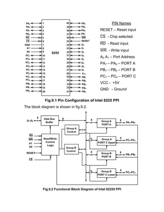
SlideShare a Scribd company logo
Lecture-49
INTEL 8255: (Programmable Peripheral Interface)
In previous lectures we have discussed how to interface I/O
devices with the system bys. If an input device, for example 8-toggle
switches, are to be interfaced with the processor, they can be
connected to data bus through 8-bit tri-state bus buffer. The status of
switches can be read using IN PORT instruction in isolated I/O mode.
The buffer is enabled during the execution of 3rd
machine cycle
(IORDMC) when IO/M =1, RD =0 and address of the device is
available on address bus. Similarly, if an output device, for example
8-LEDs are to be interfaced, they can be connected to data bus using
8-bit latch. The 8-bit data can be sent to LEDs using OUT PORT
instruction in isolated I/O mode. During the 3rd
machine cycle
(IOWRMC), the latch is enabled when IO/M =1, WR =0 and address
of the output device is available on address bus.
If the system is designed using buffer and latches to interface
input and out devices, then in future, it is not possible to change any
input device with the output device or vice-versa. In order to make it
simpler, Intel has designed 8255A chip to interface I/O devices.
The Intel 8255A is a general purpose programmable I/O device
designed for use with Intel microprocessors. It consists of three 8-bit
bidirectional I/O ports (24 I/O lines) that can be configured to meet
different system I/O needs. The three ports are designated as PORT
A, PORT B and PORT C. Port A contains one 8-bit output latch/buffer
and one 8-bit input buffer. Port B is same as PORT A or PORT B.
However, PORT C is split into two parts- PORT C lower (PC3-PC0)
and PORT C upper (PC7-PC4) by the control word. The four ports –
two 8-bit PORTs and two 4-bit PORTs are divided in two groups
Group A (PORT A and upper PORT C) Group B (PORT B and lower
PORT C) for programming purpose. These two groups can be
programmed in three different modes:
1. Mode-0
2. Mode-1
3. Mode-2
In the first mode, mode-0, each group may be programmed in either
input mode or output mode (PORT A, PORT B, PORT C lower,
PORT C upper). In mode-1, the second mode, each group may be
programmed to have 8-lines of input or output (PORT A or PORT B)
and of the remaining 4-lines (PORT C lower or PORT C upper) 3-
lines are used for handshaking and interrupt control signals. The third
mode of operation, mode-2, is a bidirectional bus mode which uses 8-
lines (PORT A) only for a bidirectional bus and five lines (PORT C
upper 4 lines and borrowing one line from PORT C lower) for
handshaking and control signals. PORT A and PORT B have both
input and output buffers and latches but PORT C has output latch
and input buffer.
The 8255A is contained in a 40-pin package, whose pin out is
shown in fig.9.1.
Fig.9.1 Pin Configuration of Intel 8225 PPI
The block diagram is shown in fig.9.2.
Fig.9.2 Functional Block Diagram of Intel 82255 PPI
1
2
3
4
5
6
7
8
9
10
11
12
13
14
15
16
17
18
19
20
37
38
39
40
D7
D6
D5
D4
D3
D2
D1
D0
VCC
WRRD
CS
8255
GND
21
22
36
35
34
33
32
31
30
29
28
27
26
25
24
23
RESET
PA0
PA1
PA2
PA3
PA7
PA6
PA5
PA4
A1
A0
PC0
PC5
PC6
PC7
PC4
PC3
PC2
PC1
PB0
PB2
PB1
PB5
PB3
PB4
PB7
PB6
Data Bus
Buffer
Read/Write
Control
Logic
D7-D0
RD
WR
A0
CS
88
Group B
Control
A1
8
4
RESET
Group A
Control
PA7-PA0
8Group A
PORT A
PC7-PC4
4
Group A
PORT C Upper
8
4
PB7-PB0
8Group B
PORT B
PC3-PC0
4
Group B
PORT C Lower
PIN Names
RESET – Reset input
CS - Chip selected
RD - Read input
WR - Write input
A0 A1 – Port Address
PA7 – PA0 – PORT A
PB7 – PB0 – PORT B
PC7 – PC0 – PORT C
VCC - +5V
GND - Ground
Functional Description:
This support chip is a general purpose I/O component to interface
peripheral equipment to the microcomputer system bus. It is
programmed by the system software so that normally no external
logic is necessary to interface peripheral devices or structures.
Data Bus Buffer:
It is a tri-state 8-bit buffer used to interface the chip to the system
data bus. Data is transmitted or received by the buffer upon execution
of input or output instructions by the CPU. Control words and status
information are also transferred through the data bus buffer. The data
lines are connected to BDB of 𝜇p.
Read/Write and Logic Control:
The function of this block is to control the internal operation of the
device and to control the transfer of data and control or status words.
It accepts inputs from the CPU address and control buses and, in
turn, issues command to both the control groups.
CS (Chip Select):
A low on this input selects the chip and enables the communication
between 8255A & the CPU. It is connected to the output of address
decode circuitry to select the device when it is addressed.
RD (Read):
A low on this input enables the 8255A to send the data or status
information to the CPU on the data bus.
WR (Write):
A low on this input pin enables the CPU to write data or control words
into the 8255A.
A1, A0 Port Select:
These input signals, in conjunction with the RD and WR inputs,
control the selection of one of the three ports or the control word
registers. They are normally connected to the least significant bits of
the address bus (A0 and A1).
The basic operation of these control signals is given in the
following Table:
A1 A0 RD WR CS Input –Output operation
0 0 0 1 0 PORT A Data bus
0 1 0 1 0 PORT B Data bus
1 0 0 1 0 PORT C Data bus
0 0 1 0 0 Data bus PORT A
0 1 1 0 0 Data bus PORT B
1 0 1 0 0 Data bus PORT C
1 1 1 0 0 Data bus CWR
All other states put data bus into tri-state/illegal condition.
RESET:
A high on this input pin clears the control register and all ports (PORT
A, PORT B & PORT C) are initialized in input mode. This is
connected to RESET OUT of 8085A. This is done to prevent
destruction of circuitry connected to port lines. If port lines are
initialized as output after a power up or reset, the port might try to
output into the output of a device connected to same inputs might
destroy one or both of them.
To understand why the programmable ports are automatically
programmed in input mode just after power on or reset, let us
consider the port is programmed by default in output mode. The user
might have connected an output device (LEDs) or an input device
(toggle switches) to the port before switching on power as shown in
fig.9.3.
Fig.9.3 Ports Programmed as Output Port by Default
The port, if programmed in output mode, derives the output lines and
the data flows from the port to device. Whatever may be the default
data output, the LEDs will be switched on or off accordingly. If an
input device is connected to the same port (programmed in output
mode by default), then the output device (toggle switches) also drives
the data lines. The data lines will be driven from both the ends and,
therefore, there will be data bus contamination.
Now let us consider the port is programmed in input mode by
default and the user has connected either input device or an output
Port
Programmed
as Output
Output
Device
Direction of data flow
Port
Programmed
as Output
Input
Device
Data Bus Conflict as both Port
and Device Outputs the data
device to this port as shown in fig.9.4. If an input device is connected
to the port, the device drives the data lines and the port accepts the
data from these lines. The data flows from the device to the port.
However, if an output device is connected to this port (programmed
by default in input mode), both the device and the port can only
accept data from the data lines. In this case, no data flow takes place
but there will be no data bus contamination. After switch on, the port
will be programmed in desired mode. That is the reason why
programmable ports are programmed in input mode just after power
on or reset.
Fig.9.4 Ports Programmed as Input Port by Default
PORTs A, B and C:
The 8255A contains three 8-bit ports (A, B and C). All can be
configured in a variety of functional characteristic by the system
software.
PORT A:
One 8-bit data output latch/buffer and one 8-bit data input latch.
Port
Programmed
as Input
Output
Device
Direction of data flow
Port
Programmed
as Input
Input
Device
No Data Bus Conflict as both
Port and Device can accept the
data from the bus
PORT B:
One 8-bit data output latch/buffer and one 8-bit data input buffer.
PORT C:
One 8-bit data output latch/buffer and one 8-bit data input buffer (no
latch for input). This port can be divided into two 4-bit ports under the
mode control. Each 4-bit port contains a 4-bit latch and it can be used
for the control signal outputs and status signals inputs in conjunction
with ports A and B.
Group A & Group B control:
The functional configuration of each port is programmed by the
system software. The control words outputted by the CPU configure
the associated ports of the each of the two groups. Each control block
accepts command from Read/Write content logic receives control
words from the internal data bus and issues proper commands to its
associated ports.
Control Group A – Port A & Port C upper
Control Group B – Port B & Port C lower
The control word register can only be written into. No read operation
of the control word register is allowed.

More Related Content

What's hot

8255 Programmble Peripheral Interface
8255 Programmble Peripheral Interface8255 Programmble Peripheral Interface
8255 Programmble Peripheral Interface
Amit Kumer Podder
 
Programmableperipheralinterface 8255 ppt
Programmableperipheralinterface 8255 pptProgrammableperipheralinterface 8255 ppt
Programmableperipheralinterface 8255 ppt
sharan Kumar
 
Unit 3-1 (1)
Unit 3-1 (1)Unit 3-1 (1)
Unit 3-1 (1)
Vasu Ch
 
8255 PPI or parallel interface
8255 PPI or parallel interface8255 PPI or parallel interface
8255 PPI or parallel interface
Akkenaguntla Karthik
 
Microprocessor Basics 8085-8255 ch-5
Microprocessor Basics 8085-8255 ch-5Microprocessor Basics 8085-8255 ch-5
Microprocessor Basics 8085-8255 ch-5
Neelam Kapoor
 
8085 Interfacing with I/O Devices or Memory
8085 Interfacing with I/O Devices or Memory8085 Interfacing with I/O Devices or Memory
8085 Interfacing with I/O Devices or Memory
Saumay Paul
 
8255 Introduction
8255 Introduction8255 Introduction
8255 Introduction
SharmilaChidaravalli
 
The 8255 PPI
The 8255 PPIThe 8255 PPI
The 8255 PPI
Srikrishna Thota
 
Intel 8086 internal architecture & pin diagram
Intel 8086 internal architecture & pin diagramIntel 8086 internal architecture & pin diagram
Intel 8086 internal architecture & pin diagram
krunal47
 
1.ppi 8255
1.ppi 8255 1.ppi 8255
1.ppi 8255
MdFazleRabbi18
 
PIN Specification of 8086 Microprocessor
PIN Specification of 8086 MicroprocessorPIN Specification of 8086 Microprocessor
PIN Specification of 8086 Microprocessor
Nikhil Kumar
 
Interfacing of 8255 IC By Er. Swapnil Kaware.
Interfacing of 8255 IC By Er. Swapnil Kaware.Interfacing of 8255 IC By Er. Swapnil Kaware.
Interfacing of 8255 IC By Er. Swapnil Kaware.
Prof. Swapnil V. Kaware
 
8085 lab
8085 lab8085 lab
8085 lab
Nithin Mohan
 
8255_Ppi new
8255_Ppi new8255_Ppi new
8255_Ppi new
Monica Gunjal
 
MICROPROCESSOR INPUT OUTPUT OPERATIONS
MICROPROCESSOR INPUT OUTPUT OPERATIONSMICROPROCESSOR INPUT OUTPUT OPERATIONS
MICROPROCESSOR INPUT OUTPUT OPERATIONS
George Thomas
 
DMA controller intel 8257
DMA controller intel 8257DMA controller intel 8257
DMA controller intel 8257
Daniel Ilunga
 
Basics of peripheral devices and Working
Basics of peripheral devices and WorkingBasics of peripheral devices and Working
Basics of peripheral devices and Working
Dr.YNM
 
Microprocessor & Interfacing (Part-2) By Er. Swapnil V. Kaware
Microprocessor & Interfacing (Part-2) By Er. Swapnil V. KawareMicroprocessor & Interfacing (Part-2) By Er. Swapnil V. Kaware
Microprocessor & Interfacing (Part-2) By Er. Swapnil V. Kaware
Prof. Swapnil V. Kaware
 
8085 instruction-set part 1
8085 instruction-set part 18085 instruction-set part 1
8085 instruction-set part 1
RENUKASHIRBAVIKAR1
 
8255 ppi
8255 ppi8255 ppi
8255 ppi
Suraj Bora
 

What's hot (20)

8255 Programmble Peripheral Interface
8255 Programmble Peripheral Interface8255 Programmble Peripheral Interface
8255 Programmble Peripheral Interface
 
Programmableperipheralinterface 8255 ppt
Programmableperipheralinterface 8255 pptProgrammableperipheralinterface 8255 ppt
Programmableperipheralinterface 8255 ppt
 
Unit 3-1 (1)
Unit 3-1 (1)Unit 3-1 (1)
Unit 3-1 (1)
 
8255 PPI or parallel interface
8255 PPI or parallel interface8255 PPI or parallel interface
8255 PPI or parallel interface
 
Microprocessor Basics 8085-8255 ch-5
Microprocessor Basics 8085-8255 ch-5Microprocessor Basics 8085-8255 ch-5
Microprocessor Basics 8085-8255 ch-5
 
8085 Interfacing with I/O Devices or Memory
8085 Interfacing with I/O Devices or Memory8085 Interfacing with I/O Devices or Memory
8085 Interfacing with I/O Devices or Memory
 
8255 Introduction
8255 Introduction8255 Introduction
8255 Introduction
 
The 8255 PPI
The 8255 PPIThe 8255 PPI
The 8255 PPI
 
Intel 8086 internal architecture & pin diagram
Intel 8086 internal architecture & pin diagramIntel 8086 internal architecture & pin diagram
Intel 8086 internal architecture & pin diagram
 
1.ppi 8255
1.ppi 8255 1.ppi 8255
1.ppi 8255
 
PIN Specification of 8086 Microprocessor
PIN Specification of 8086 MicroprocessorPIN Specification of 8086 Microprocessor
PIN Specification of 8086 Microprocessor
 
Interfacing of 8255 IC By Er. Swapnil Kaware.
Interfacing of 8255 IC By Er. Swapnil Kaware.Interfacing of 8255 IC By Er. Swapnil Kaware.
Interfacing of 8255 IC By Er. Swapnil Kaware.
 
8085 lab
8085 lab8085 lab
8085 lab
 
8255_Ppi new
8255_Ppi new8255_Ppi new
8255_Ppi new
 
MICROPROCESSOR INPUT OUTPUT OPERATIONS
MICROPROCESSOR INPUT OUTPUT OPERATIONSMICROPROCESSOR INPUT OUTPUT OPERATIONS
MICROPROCESSOR INPUT OUTPUT OPERATIONS
 
DMA controller intel 8257
DMA controller intel 8257DMA controller intel 8257
DMA controller intel 8257
 
Basics of peripheral devices and Working
Basics of peripheral devices and WorkingBasics of peripheral devices and Working
Basics of peripheral devices and Working
 
Microprocessor & Interfacing (Part-2) By Er. Swapnil V. Kaware
Microprocessor & Interfacing (Part-2) By Er. Swapnil V. KawareMicroprocessor & Interfacing (Part-2) By Er. Swapnil V. Kaware
Microprocessor & Interfacing (Part-2) By Er. Swapnil V. Kaware
 
8085 instruction-set part 1
8085 instruction-set part 18085 instruction-set part 1
8085 instruction-set part 1
 
8255 ppi
8255 ppi8255 ppi
8255 ppi
 

Similar to 363118864 8255-nptel

8255 PPI
8255 PPI8255 PPI
8255 PPI
deval patel
 
Mod-2 M&M.pptx
Mod-2 M&M.pptxMod-2 M&M.pptx
Mod-2 M&M.pptx
TechCook1
 
8255 ppi.pptx
8255 ppi.pptx8255 ppi.pptx
8255 ppi.pptx
zahid235639
 
unit-3-8255.pdf
unit-3-8255.pdfunit-3-8255.pdf
unit-3-8255.pdf
ShanmukhSaiR
 
8255-PPI MPMC text book for engineering.ppt
8255-PPI MPMC text book for engineering.ppt8255-PPI MPMC text book for engineering.ppt
8255-PPI MPMC text book for engineering.ppt
khushiduppala
 
8255 & IO Interfacing.pdf
8255 & IO Interfacing.pdf8255 & IO Interfacing.pdf
8255 & IO Interfacing.pdf
Ilavarasan Tamizh
 
8255 ppi students material for ppi mpmc study
8255 ppi students material for ppi mpmc study8255 ppi students material for ppi mpmc study
8255 ppi students material for ppi mpmc study
Sirisha Vamsi
 
MicroProcessors and MicroControllersUnit3
MicroProcessors and MicroControllersUnit3MicroProcessors and MicroControllersUnit3
MicroProcessors and MicroControllersUnit3
deepakdmaat
 
UNIT 3 Peripheral Interfacing.pptx
UNIT 3 Peripheral Interfacing.pptxUNIT 3 Peripheral Interfacing.pptx
UNIT 3 Peripheral Interfacing.pptx
Gowrishankar C
 
8255 presentaion.ppt
8255 presentaion.ppt8255 presentaion.ppt
8255 presentaion.ppt
kamlesh deshmukh
 
Unit iii microcontrollers final1
Unit iii microcontrollers final1Unit iii microcontrollers final1
Unit iii microcontrollers final1
Saritha Reddy
 
Io (2)
Io (2)Io (2)
Io (2)
Aisu
 
8255_utkarsh_kulshrestha
8255_utkarsh_kulshrestha8255_utkarsh_kulshrestha
8255_utkarsh_kulshrestha
Utkarsh Kulshrestha
 
8085-microprocessor
8085-microprocessor8085-microprocessor
8085-microprocessor
ATTO RATHORE
 
INTERFACING WITH INTEL 8251A (USART)
INTERFACING WITH INTEL 8251A (USART)INTERFACING WITH INTEL 8251A (USART)
INTERFACING WITH INTEL 8251A (USART)
Prof Ansari
 
INTERFACING WITH INTEL 8251A (USART)
INTERFACING WITH INTEL 8251A (USART)INTERFACING WITH INTEL 8251A (USART)
INTERFACING WITH INTEL 8251A (USART)
Prof Ansari
 
8251 communication interface
8251 communication interface8251 communication interface
8251 communication interface
LingalaSowjanya
 
8251 usart programmable communication interface by aniket bhute
8251  usart  programmable communication interface by aniket bhute8251  usart  programmable communication interface by aniket bhute
8251 usart programmable communication interface by aniket bhute
Aniket Bhute
 
Microprocessor Interfacing and 8155 Features
Microprocessor Interfacing and 8155 FeaturesMicroprocessor Interfacing and 8155 Features
Microprocessor Interfacing and 8155 Features
Srikrishna Thota
 
L4-L6 8255 A.pptx
L4-L6 8255 A.pptxL4-L6 8255 A.pptx
L4-L6 8255 A.pptx
Motaleb Hossen Manik
 

Similar to 363118864 8255-nptel (20)

8255 PPI
8255 PPI8255 PPI
8255 PPI
 
Mod-2 M&M.pptx
Mod-2 M&M.pptxMod-2 M&M.pptx
Mod-2 M&M.pptx
 
8255 ppi.pptx
8255 ppi.pptx8255 ppi.pptx
8255 ppi.pptx
 
unit-3-8255.pdf
unit-3-8255.pdfunit-3-8255.pdf
unit-3-8255.pdf
 
8255-PPI MPMC text book for engineering.ppt
8255-PPI MPMC text book for engineering.ppt8255-PPI MPMC text book for engineering.ppt
8255-PPI MPMC text book for engineering.ppt
 
8255 & IO Interfacing.pdf
8255 & IO Interfacing.pdf8255 & IO Interfacing.pdf
8255 & IO Interfacing.pdf
 
8255 ppi students material for ppi mpmc study
8255 ppi students material for ppi mpmc study8255 ppi students material for ppi mpmc study
8255 ppi students material for ppi mpmc study
 
MicroProcessors and MicroControllersUnit3
MicroProcessors and MicroControllersUnit3MicroProcessors and MicroControllersUnit3
MicroProcessors and MicroControllersUnit3
 
UNIT 3 Peripheral Interfacing.pptx
UNIT 3 Peripheral Interfacing.pptxUNIT 3 Peripheral Interfacing.pptx
UNIT 3 Peripheral Interfacing.pptx
 
8255 presentaion.ppt
8255 presentaion.ppt8255 presentaion.ppt
8255 presentaion.ppt
 
Unit iii microcontrollers final1
Unit iii microcontrollers final1Unit iii microcontrollers final1
Unit iii microcontrollers final1
 
Io (2)
Io (2)Io (2)
Io (2)
 
8255_utkarsh_kulshrestha
8255_utkarsh_kulshrestha8255_utkarsh_kulshrestha
8255_utkarsh_kulshrestha
 
8085-microprocessor
8085-microprocessor8085-microprocessor
8085-microprocessor
 
INTERFACING WITH INTEL 8251A (USART)
INTERFACING WITH INTEL 8251A (USART)INTERFACING WITH INTEL 8251A (USART)
INTERFACING WITH INTEL 8251A (USART)
 
INTERFACING WITH INTEL 8251A (USART)
INTERFACING WITH INTEL 8251A (USART)INTERFACING WITH INTEL 8251A (USART)
INTERFACING WITH INTEL 8251A (USART)
 
8251 communication interface
8251 communication interface8251 communication interface
8251 communication interface
 
8251 usart programmable communication interface by aniket bhute
8251  usart  programmable communication interface by aniket bhute8251  usart  programmable communication interface by aniket bhute
8251 usart programmable communication interface by aniket bhute
 
Microprocessor Interfacing and 8155 Features
Microprocessor Interfacing and 8155 FeaturesMicroprocessor Interfacing and 8155 Features
Microprocessor Interfacing and 8155 Features
 
L4-L6 8255 A.pptx
L4-L6 8255 A.pptxL4-L6 8255 A.pptx
L4-L6 8255 A.pptx
 

Recently uploaded

A Independência da América Espanhola LAPBOOK.pdf
A Independência da América Espanhola LAPBOOK.pdfA Independência da América Espanhola LAPBOOK.pdf
A Independência da América Espanhola LAPBOOK.pdf
Jean Carlos Nunes Paixão
 
Chapter wise All Notes of First year Basic Civil Engineering.pptx
Chapter wise All Notes of First year Basic Civil Engineering.pptxChapter wise All Notes of First year Basic Civil Engineering.pptx
Chapter wise All Notes of First year Basic Civil Engineering.pptx
Denish Jangid
 
Bonku-Babus-Friend by Sathyajith Ray (9)
Bonku-Babus-Friend by Sathyajith Ray  (9)Bonku-Babus-Friend by Sathyajith Ray  (9)
Bonku-Babus-Friend by Sathyajith Ray (9)
nitinpv4ai
 
How to Make a Field Mandatory in Odoo 17
How to Make a Field Mandatory in Odoo 17How to Make a Field Mandatory in Odoo 17
How to Make a Field Mandatory in Odoo 17
Celine George
 
How to deliver Powerpoint Presentations.pptx
How to deliver Powerpoint  Presentations.pptxHow to deliver Powerpoint  Presentations.pptx
How to deliver Powerpoint Presentations.pptx
HajraNaeem15
 
Temple of Asclepius in Thrace. Excavation results
Temple of Asclepius in Thrace. Excavation resultsTemple of Asclepius in Thrace. Excavation results
Temple of Asclepius in Thrace. Excavation results
Krassimira Luka
 
How to Setup Warehouse & Location in Odoo 17 Inventory
How to Setup Warehouse & Location in Odoo 17 InventoryHow to Setup Warehouse & Location in Odoo 17 Inventory
How to Setup Warehouse & Location in Odoo 17 Inventory
Celine George
 
Mule event processing models | MuleSoft Mysore Meetup #47
Mule event processing models | MuleSoft Mysore Meetup #47Mule event processing models | MuleSoft Mysore Meetup #47
Mule event processing models | MuleSoft Mysore Meetup #47
MysoreMuleSoftMeetup
 
The History of Stoke Newington Street Names
The History of Stoke Newington Street NamesThe History of Stoke Newington Street Names
The History of Stoke Newington Street Names
History of Stoke Newington
 
Gender and Mental Health - Counselling and Family Therapy Applications and In...
Gender and Mental Health - Counselling and Family Therapy Applications and In...Gender and Mental Health - Counselling and Family Therapy Applications and In...
Gender and Mental Health - Counselling and Family Therapy Applications and In...
PsychoTech Services
 
Stack Memory Organization of 8086 Microprocessor
Stack Memory Organization of 8086 MicroprocessorStack Memory Organization of 8086 Microprocessor
Stack Memory Organization of 8086 Microprocessor
JomonJoseph58
 
REASIGNACION 2024 UGEL CHUPACA 2024 UGEL CHUPACA.pdf
REASIGNACION 2024 UGEL CHUPACA 2024 UGEL CHUPACA.pdfREASIGNACION 2024 UGEL CHUPACA 2024 UGEL CHUPACA.pdf
REASIGNACION 2024 UGEL CHUPACA 2024 UGEL CHUPACA.pdf
giancarloi8888
 
BBR 2024 Summer Sessions Interview Training
BBR  2024 Summer Sessions Interview TrainingBBR  2024 Summer Sessions Interview Training
BBR 2024 Summer Sessions Interview Training
Katrina Pritchard
 
C1 Rubenstein AP HuG xxxxxxxxxxxxxx.pptx
C1 Rubenstein AP HuG xxxxxxxxxxxxxx.pptxC1 Rubenstein AP HuG xxxxxxxxxxxxxx.pptx
C1 Rubenstein AP HuG xxxxxxxxxxxxxx.pptx
mulvey2
 
RHEOLOGY Physical pharmaceutics-II notes for B.pharm 4th sem students
RHEOLOGY Physical pharmaceutics-II notes for B.pharm 4th sem studentsRHEOLOGY Physical pharmaceutics-II notes for B.pharm 4th sem students
RHEOLOGY Physical pharmaceutics-II notes for B.pharm 4th sem students
Himanshu Rai
 
Nutrition Inc FY 2024, 4 - Hour Training
Nutrition Inc FY 2024, 4 - Hour TrainingNutrition Inc FY 2024, 4 - Hour Training
Nutrition Inc FY 2024, 4 - Hour Training
melliereed
 
Lifelines of National Economy chapter for Class 10 STUDY MATERIAL PDF
Lifelines of National Economy chapter for Class 10 STUDY MATERIAL PDFLifelines of National Economy chapter for Class 10 STUDY MATERIAL PDF
Lifelines of National Economy chapter for Class 10 STUDY MATERIAL PDF
Vivekanand Anglo Vedic Academy
 
BÀI TẬP DẠY THÊM TIẾNG ANH LỚP 7 CẢ NĂM FRIENDS PLUS SÁCH CHÂN TRỜI SÁNG TẠO ...
BÀI TẬP DẠY THÊM TIẾNG ANH LỚP 7 CẢ NĂM FRIENDS PLUS SÁCH CHÂN TRỜI SÁNG TẠO ...BÀI TẬP DẠY THÊM TIẾNG ANH LỚP 7 CẢ NĂM FRIENDS PLUS SÁCH CHÂN TRỜI SÁNG TẠO ...
BÀI TẬP DẠY THÊM TIẾNG ANH LỚP 7 CẢ NĂM FRIENDS PLUS SÁCH CHÂN TRỜI SÁNG TẠO ...
Nguyen Thanh Tu Collection
 
Film vocab for eal 3 students: Australia the movie
Film vocab for eal 3 students: Australia the movieFilm vocab for eal 3 students: Australia the movie
Film vocab for eal 3 students: Australia the movie
Nicholas Montgomery
 
Wound healing PPT
Wound healing PPTWound healing PPT
Wound healing PPT
Jyoti Chand
 

Recently uploaded (20)

A Independência da América Espanhola LAPBOOK.pdf
A Independência da América Espanhola LAPBOOK.pdfA Independência da América Espanhola LAPBOOK.pdf
A Independência da América Espanhola LAPBOOK.pdf
 
Chapter wise All Notes of First year Basic Civil Engineering.pptx
Chapter wise All Notes of First year Basic Civil Engineering.pptxChapter wise All Notes of First year Basic Civil Engineering.pptx
Chapter wise All Notes of First year Basic Civil Engineering.pptx
 
Bonku-Babus-Friend by Sathyajith Ray (9)
Bonku-Babus-Friend by Sathyajith Ray  (9)Bonku-Babus-Friend by Sathyajith Ray  (9)
Bonku-Babus-Friend by Sathyajith Ray (9)
 
How to Make a Field Mandatory in Odoo 17
How to Make a Field Mandatory in Odoo 17How to Make a Field Mandatory in Odoo 17
How to Make a Field Mandatory in Odoo 17
 
How to deliver Powerpoint Presentations.pptx
How to deliver Powerpoint  Presentations.pptxHow to deliver Powerpoint  Presentations.pptx
How to deliver Powerpoint Presentations.pptx
 
Temple of Asclepius in Thrace. Excavation results
Temple of Asclepius in Thrace. Excavation resultsTemple of Asclepius in Thrace. Excavation results
Temple of Asclepius in Thrace. Excavation results
 
How to Setup Warehouse & Location in Odoo 17 Inventory
How to Setup Warehouse & Location in Odoo 17 InventoryHow to Setup Warehouse & Location in Odoo 17 Inventory
How to Setup Warehouse & Location in Odoo 17 Inventory
 
Mule event processing models | MuleSoft Mysore Meetup #47
Mule event processing models | MuleSoft Mysore Meetup #47Mule event processing models | MuleSoft Mysore Meetup #47
Mule event processing models | MuleSoft Mysore Meetup #47
 
The History of Stoke Newington Street Names
The History of Stoke Newington Street NamesThe History of Stoke Newington Street Names
The History of Stoke Newington Street Names
 
Gender and Mental Health - Counselling and Family Therapy Applications and In...
Gender and Mental Health - Counselling and Family Therapy Applications and In...Gender and Mental Health - Counselling and Family Therapy Applications and In...
Gender and Mental Health - Counselling and Family Therapy Applications and In...
 
Stack Memory Organization of 8086 Microprocessor
Stack Memory Organization of 8086 MicroprocessorStack Memory Organization of 8086 Microprocessor
Stack Memory Organization of 8086 Microprocessor
 
REASIGNACION 2024 UGEL CHUPACA 2024 UGEL CHUPACA.pdf
REASIGNACION 2024 UGEL CHUPACA 2024 UGEL CHUPACA.pdfREASIGNACION 2024 UGEL CHUPACA 2024 UGEL CHUPACA.pdf
REASIGNACION 2024 UGEL CHUPACA 2024 UGEL CHUPACA.pdf
 
BBR 2024 Summer Sessions Interview Training
BBR  2024 Summer Sessions Interview TrainingBBR  2024 Summer Sessions Interview Training
BBR 2024 Summer Sessions Interview Training
 
C1 Rubenstein AP HuG xxxxxxxxxxxxxx.pptx
C1 Rubenstein AP HuG xxxxxxxxxxxxxx.pptxC1 Rubenstein AP HuG xxxxxxxxxxxxxx.pptx
C1 Rubenstein AP HuG xxxxxxxxxxxxxx.pptx
 
RHEOLOGY Physical pharmaceutics-II notes for B.pharm 4th sem students
RHEOLOGY Physical pharmaceutics-II notes for B.pharm 4th sem studentsRHEOLOGY Physical pharmaceutics-II notes for B.pharm 4th sem students
RHEOLOGY Physical pharmaceutics-II notes for B.pharm 4th sem students
 
Nutrition Inc FY 2024, 4 - Hour Training
Nutrition Inc FY 2024, 4 - Hour TrainingNutrition Inc FY 2024, 4 - Hour Training
Nutrition Inc FY 2024, 4 - Hour Training
 
Lifelines of National Economy chapter for Class 10 STUDY MATERIAL PDF
Lifelines of National Economy chapter for Class 10 STUDY MATERIAL PDFLifelines of National Economy chapter for Class 10 STUDY MATERIAL PDF
Lifelines of National Economy chapter for Class 10 STUDY MATERIAL PDF
 
BÀI TẬP DẠY THÊM TIẾNG ANH LỚP 7 CẢ NĂM FRIENDS PLUS SÁCH CHÂN TRỜI SÁNG TẠO ...
BÀI TẬP DẠY THÊM TIẾNG ANH LỚP 7 CẢ NĂM FRIENDS PLUS SÁCH CHÂN TRỜI SÁNG TẠO ...BÀI TẬP DẠY THÊM TIẾNG ANH LỚP 7 CẢ NĂM FRIENDS PLUS SÁCH CHÂN TRỜI SÁNG TẠO ...
BÀI TẬP DẠY THÊM TIẾNG ANH LỚP 7 CẢ NĂM FRIENDS PLUS SÁCH CHÂN TRỜI SÁNG TẠO ...
 
Film vocab for eal 3 students: Australia the movie
Film vocab for eal 3 students: Australia the movieFilm vocab for eal 3 students: Australia the movie
Film vocab for eal 3 students: Australia the movie
 
Wound healing PPT
Wound healing PPTWound healing PPT
Wound healing PPT
 

363118864 8255-nptel

  • 1. Lecture-49 INTEL 8255: (Programmable Peripheral Interface) In previous lectures we have discussed how to interface I/O devices with the system bys. If an input device, for example 8-toggle switches, are to be interfaced with the processor, they can be connected to data bus through 8-bit tri-state bus buffer. The status of switches can be read using IN PORT instruction in isolated I/O mode. The buffer is enabled during the execution of 3rd machine cycle (IORDMC) when IO/M =1, RD =0 and address of the device is available on address bus. Similarly, if an output device, for example 8-LEDs are to be interfaced, they can be connected to data bus using 8-bit latch. The 8-bit data can be sent to LEDs using OUT PORT instruction in isolated I/O mode. During the 3rd machine cycle (IOWRMC), the latch is enabled when IO/M =1, WR =0 and address of the output device is available on address bus. If the system is designed using buffer and latches to interface input and out devices, then in future, it is not possible to change any input device with the output device or vice-versa. In order to make it simpler, Intel has designed 8255A chip to interface I/O devices. The Intel 8255A is a general purpose programmable I/O device designed for use with Intel microprocessors. It consists of three 8-bit bidirectional I/O ports (24 I/O lines) that can be configured to meet different system I/O needs. The three ports are designated as PORT A, PORT B and PORT C. Port A contains one 8-bit output latch/buffer and one 8-bit input buffer. Port B is same as PORT A or PORT B. However, PORT C is split into two parts- PORT C lower (PC3-PC0)
  • 2. and PORT C upper (PC7-PC4) by the control word. The four ports – two 8-bit PORTs and two 4-bit PORTs are divided in two groups Group A (PORT A and upper PORT C) Group B (PORT B and lower PORT C) for programming purpose. These two groups can be programmed in three different modes: 1. Mode-0 2. Mode-1 3. Mode-2 In the first mode, mode-0, each group may be programmed in either input mode or output mode (PORT A, PORT B, PORT C lower, PORT C upper). In mode-1, the second mode, each group may be programmed to have 8-lines of input or output (PORT A or PORT B) and of the remaining 4-lines (PORT C lower or PORT C upper) 3- lines are used for handshaking and interrupt control signals. The third mode of operation, mode-2, is a bidirectional bus mode which uses 8- lines (PORT A) only for a bidirectional bus and five lines (PORT C upper 4 lines and borrowing one line from PORT C lower) for handshaking and control signals. PORT A and PORT B have both input and output buffers and latches but PORT C has output latch and input buffer. The 8255A is contained in a 40-pin package, whose pin out is shown in fig.9.1.
  • 3. Fig.9.1 Pin Configuration of Intel 8225 PPI The block diagram is shown in fig.9.2. Fig.9.2 Functional Block Diagram of Intel 82255 PPI 1 2 3 4 5 6 7 8 9 10 11 12 13 14 15 16 17 18 19 20 37 38 39 40 D7 D6 D5 D4 D3 D2 D1 D0 VCC WRRD CS 8255 GND 21 22 36 35 34 33 32 31 30 29 28 27 26 25 24 23 RESET PA0 PA1 PA2 PA3 PA7 PA6 PA5 PA4 A1 A0 PC0 PC5 PC6 PC7 PC4 PC3 PC2 PC1 PB0 PB2 PB1 PB5 PB3 PB4 PB7 PB6 Data Bus Buffer Read/Write Control Logic D7-D0 RD WR A0 CS 88 Group B Control A1 8 4 RESET Group A Control PA7-PA0 8Group A PORT A PC7-PC4 4 Group A PORT C Upper 8 4 PB7-PB0 8Group B PORT B PC3-PC0 4 Group B PORT C Lower PIN Names RESET – Reset input CS - Chip selected RD - Read input WR - Write input A0 A1 – Port Address PA7 – PA0 – PORT A PB7 – PB0 – PORT B PC7 – PC0 – PORT C VCC - +5V GND - Ground
  • 4. Functional Description: This support chip is a general purpose I/O component to interface peripheral equipment to the microcomputer system bus. It is programmed by the system software so that normally no external logic is necessary to interface peripheral devices or structures. Data Bus Buffer: It is a tri-state 8-bit buffer used to interface the chip to the system data bus. Data is transmitted or received by the buffer upon execution of input or output instructions by the CPU. Control words and status information are also transferred through the data bus buffer. The data lines are connected to BDB of 𝜇p. Read/Write and Logic Control: The function of this block is to control the internal operation of the device and to control the transfer of data and control or status words. It accepts inputs from the CPU address and control buses and, in turn, issues command to both the control groups. CS (Chip Select): A low on this input selects the chip and enables the communication between 8255A & the CPU. It is connected to the output of address decode circuitry to select the device when it is addressed. RD (Read): A low on this input enables the 8255A to send the data or status information to the CPU on the data bus.
  • 5. WR (Write): A low on this input pin enables the CPU to write data or control words into the 8255A. A1, A0 Port Select: These input signals, in conjunction with the RD and WR inputs, control the selection of one of the three ports or the control word registers. They are normally connected to the least significant bits of the address bus (A0 and A1). The basic operation of these control signals is given in the following Table: A1 A0 RD WR CS Input –Output operation 0 0 0 1 0 PORT A Data bus 0 1 0 1 0 PORT B Data bus 1 0 0 1 0 PORT C Data bus 0 0 1 0 0 Data bus PORT A 0 1 1 0 0 Data bus PORT B 1 0 1 0 0 Data bus PORT C 1 1 1 0 0 Data bus CWR All other states put data bus into tri-state/illegal condition. RESET: A high on this input pin clears the control register and all ports (PORT A, PORT B & PORT C) are initialized in input mode. This is connected to RESET OUT of 8085A. This is done to prevent destruction of circuitry connected to port lines. If port lines are
  • 6. initialized as output after a power up or reset, the port might try to output into the output of a device connected to same inputs might destroy one or both of them. To understand why the programmable ports are automatically programmed in input mode just after power on or reset, let us consider the port is programmed by default in output mode. The user might have connected an output device (LEDs) or an input device (toggle switches) to the port before switching on power as shown in fig.9.3. Fig.9.3 Ports Programmed as Output Port by Default The port, if programmed in output mode, derives the output lines and the data flows from the port to device. Whatever may be the default data output, the LEDs will be switched on or off accordingly. If an input device is connected to the same port (programmed in output mode by default), then the output device (toggle switches) also drives the data lines. The data lines will be driven from both the ends and, therefore, there will be data bus contamination. Now let us consider the port is programmed in input mode by default and the user has connected either input device or an output Port Programmed as Output Output Device Direction of data flow Port Programmed as Output Input Device Data Bus Conflict as both Port and Device Outputs the data
  • 7. device to this port as shown in fig.9.4. If an input device is connected to the port, the device drives the data lines and the port accepts the data from these lines. The data flows from the device to the port. However, if an output device is connected to this port (programmed by default in input mode), both the device and the port can only accept data from the data lines. In this case, no data flow takes place but there will be no data bus contamination. After switch on, the port will be programmed in desired mode. That is the reason why programmable ports are programmed in input mode just after power on or reset. Fig.9.4 Ports Programmed as Input Port by Default PORTs A, B and C: The 8255A contains three 8-bit ports (A, B and C). All can be configured in a variety of functional characteristic by the system software. PORT A: One 8-bit data output latch/buffer and one 8-bit data input latch. Port Programmed as Input Output Device Direction of data flow Port Programmed as Input Input Device No Data Bus Conflict as both Port and Device can accept the data from the bus
  • 8. PORT B: One 8-bit data output latch/buffer and one 8-bit data input buffer. PORT C: One 8-bit data output latch/buffer and one 8-bit data input buffer (no latch for input). This port can be divided into two 4-bit ports under the mode control. Each 4-bit port contains a 4-bit latch and it can be used for the control signal outputs and status signals inputs in conjunction with ports A and B. Group A & Group B control: The functional configuration of each port is programmed by the system software. The control words outputted by the CPU configure the associated ports of the each of the two groups. Each control block accepts command from Read/Write content logic receives control words from the internal data bus and issues proper commands to its associated ports. Control Group A – Port A & Port C upper Control Group B – Port B & Port C lower The control word register can only be written into. No read operation of the control word register is allowed.