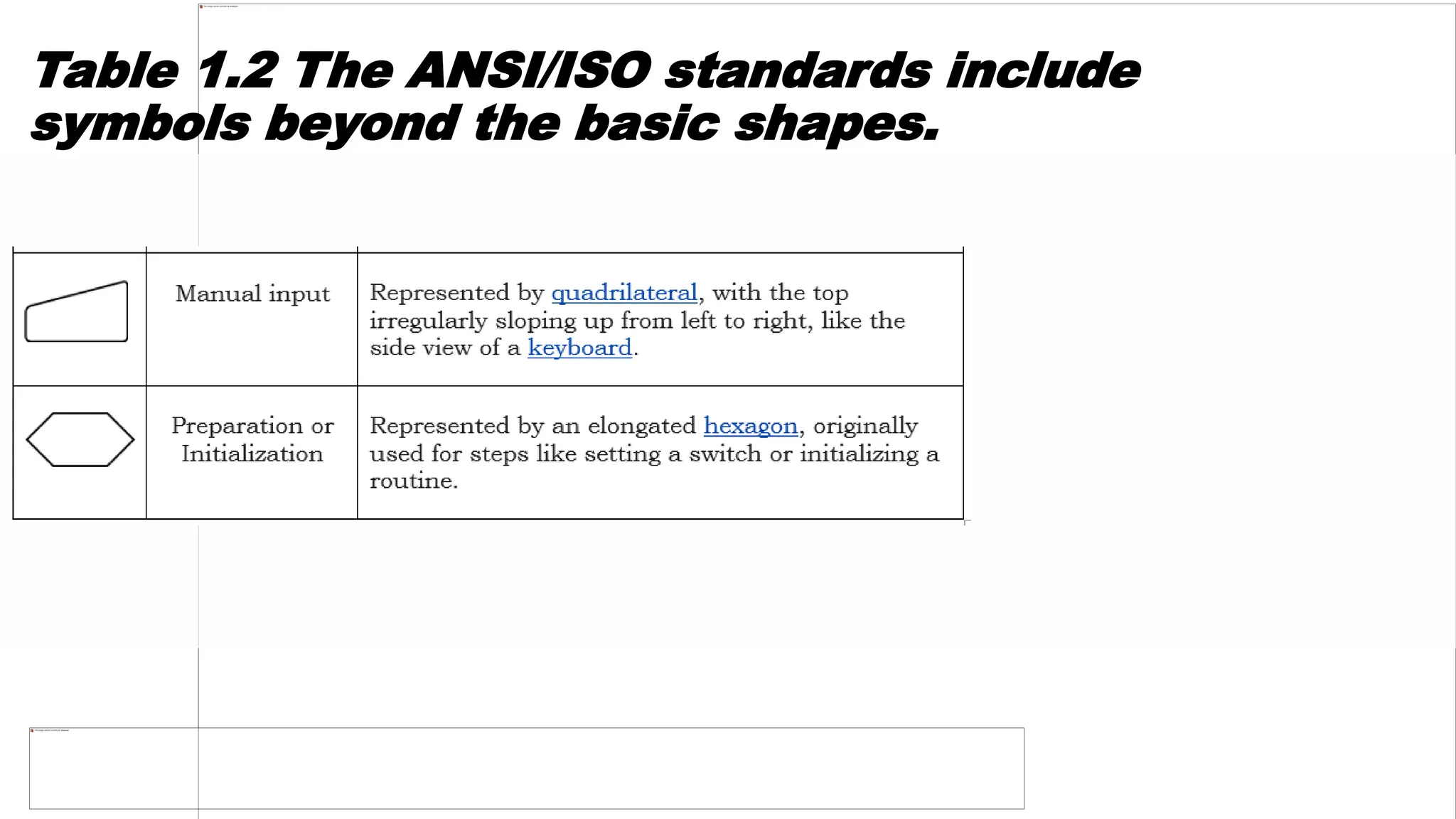
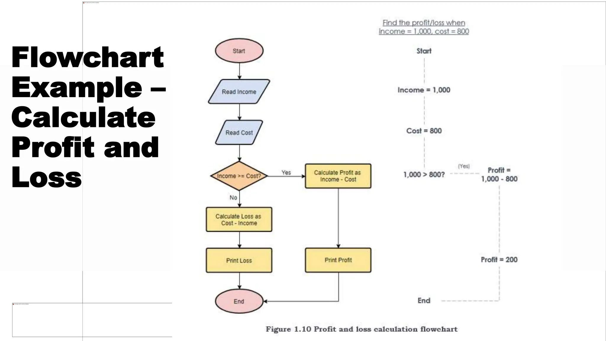
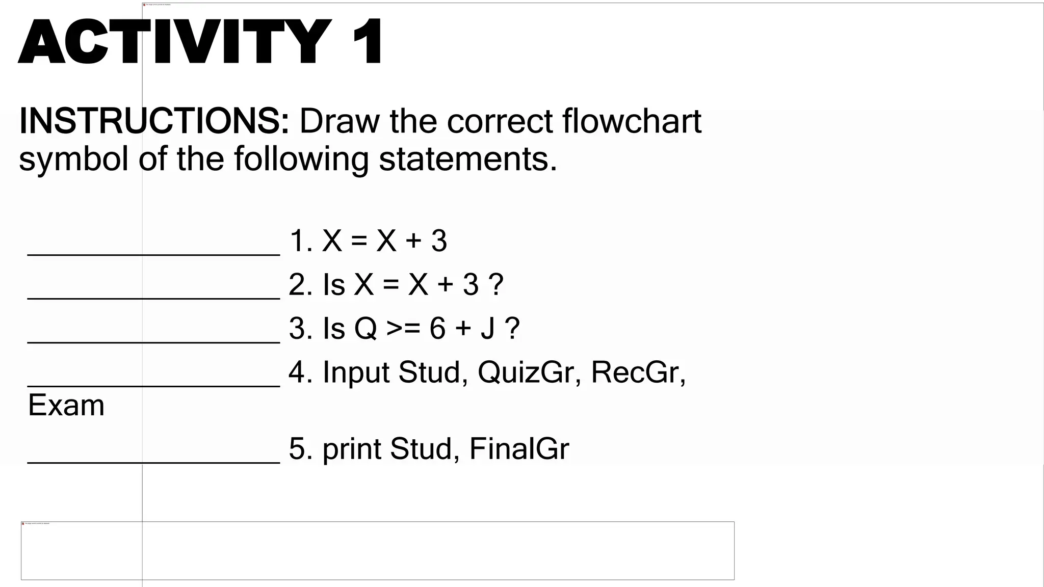
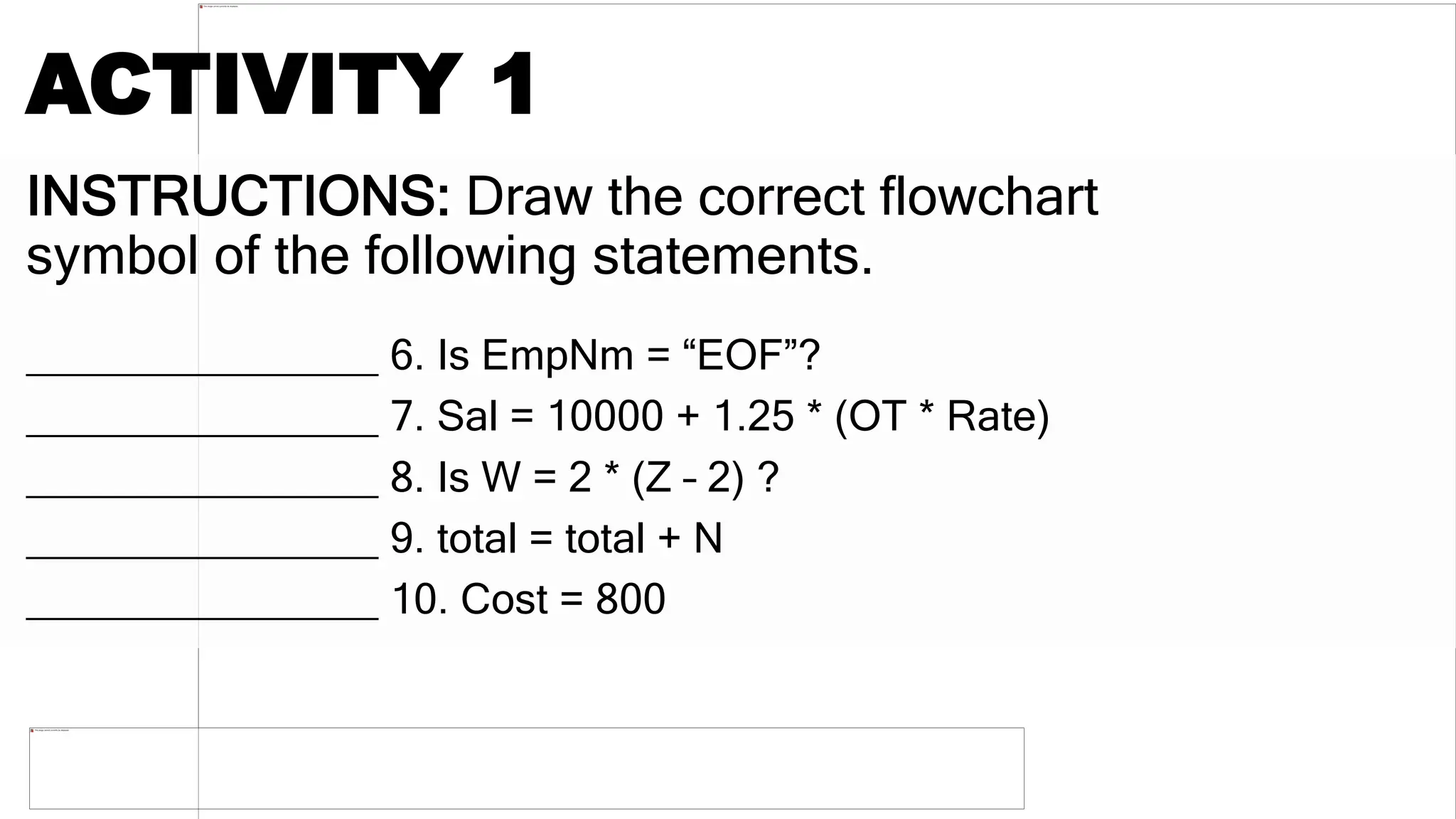
COMPUTER
PROGRAMMING
HIGH 5
San Policarpo National High School
Prayer
AVP
PICTOWORD
MECHANICS
• You need to “read” two pictures to form a word.
Example:
Answer: Earrings
1st Picture
1st Picture
Answer: ALGORITHM
2nd Picture
2nd Picture
Answer: SYMBOL
3rd Picture
3rd Picture
Answer: FLOWCHART
OBJECTIVES
1. Identify the ANSI Standard flowchart
symbols.
2. Draw a flowchart using ANSI Standard
symbols.
3. Appreciate the importance of using ANSI
Standard flowchart symbols.
N NQMNM,j7u ,shy wz7x ZX Zswa` nProgramming uses algorithm – an algorithm being a set of ordered steps for solving a
problem, and essentially a synonyms of logic. Analytical and critical thinking is needed in the formulation of solution to a
problem.
zn znj;sw8onn
PROGRAMMING
the art and science of creating programs.
 program is a list of organized instructions
that the computer must follow in order to
follow in order to process data into
information.
Coding
 an activity that involves typing words and
numbers in a computer.
Programming uses algorithm – an algorithm
being a set of ordered steps for solving a
problem, and essentially a synonyms of logic.
Analytical and critical thinking is needed in the
formulation of solution to a problem.
What is a Flowcharts?
• A flowchart is a visual outline of an
algorithm in which the steps and
processes to be followed are
represented by symbols.
• There are actually two kinds of
flowcharts: the system flowcharts
and the program flowchart.
SYSTEM FLOWCHART
• is a diagrammatic representation
of the broad flow of work,
documents and operations.
• A system flowchart shows what
job is to be done.
PROGRAM FLOWCHART
• is a diagrammatic representation
of a solution to a given problem for
which the program is written.
• A program flowchart shows how
the job is to be done.
History of Flowcharts
• The first structured method for documenting process
flow, the "flow process chart", was introduced by
Frank and Lillian Gilbreth in the presentation
"Process Charts: First Steps in Finding the One Best
Way to do Work", to members of the American
Society of Mechanical Engineers (ASME) in 1921.
History of Flowcharts
• In the early 1930s, an industrial engineer,
Allan H. Mogensen began to train
business people in the use of some of the
tools of industrial engineering at his Work
Simplification Conferences in Lake
Placid, New York.
History of Flowcharts
• Art Spinanger, a 1944 graduate of
Mogensen's class, took the tools back to
Procter and Gamble where he developed
their Deliberate Methods Change
Program.
History of Flowcharts
• Ben S. Graham, another 1944 graduate,
Director of Formcraft Engineering at
Standard Register Industrial, applied the
flow process chart to information
processing with his development of the
multi-flow process chart, to present
multiple documents and their
relationships.
History of Flowcharts
• In 1947, ASME adopted a symbol set
derived from Gilbreth's original work as
the "ASME Standard: Operation and
Flow Process Charts."
History of Flowcharts
• Douglas Hartree in 1949 explained that
Herman Goldstine and John von
Neumann had developed a flowchart
(originally, diagram) to plan computer
programs.
History of Flowcharts
• The original programming flowcharts of
Goldstine and von Neumann can be
found in their unpublished report,
"Planning and coding of problems for an
electronic computing instrument, Part II,
Volume 1" (1947), which is reproduced in
von Neumann's collected works.
History of Flowcharts
• The flowchart became a popular tool for
describing computer algorithms, but its
popularity decreased in the 1970s, when
interactive computer terminals and third-
generation programming languages
became common tools for computer
programming,
History of Flowcharts
• The flowchart became a popular tool for
describing computer algorithms, but its
popularity decreased in the 1970s, when
interactive computer terminals and third-
generation programming languages became
common tools for computer programming.
History of Flowcharts
• The flowchart became a popular tool for
describing computer algorithms, but its
popularity decreased in the 1970s, when
interactive computer terminals and third-
generation programming languages
became common tools for computer
programming,
ARRANGE ME!
FIGURE 1.1 A PAYROLL PROGRAM ALGORITHM WITH ITS
PSEUDOCODE
Figure 1.2 A program
flowchart for the problem
in Fig. 1.2
Table 1.1 ANSI Standard Flowchart
Symbols
Table 1.1 ANSI Standard Flowchart
Symbols
Table 1.2 The ANSI/ISO standards include
symbols beyond the basic shapes.
Table 1.2 The ANSI/ISO standards include
symbols beyond the basic shapes.
GENERAL RULES FOR
FLOWCHARTING
1. All boxes of the flowchart are connected with
Arrows. (Not lines)
2. Flowchart symbols have an entry point on the top
of the symbol with no other entry points. The exit
point for all flowchart symbols is on the bottom
except for the Decision symbol.
3. The Decision symbol has two exit points; these
can be on the sides or the bottom and one side.
GENERAL RULES FOR
FLOWCHARTING
4. Generally a flowchart will flow from top to
bottom. However, an upward flow can be shown
as long as it does not exceed 3 symbols.
5. Connectors are used to connect breaks in the
flowchart. Examples are:
o From one page to another page.
o From the bottom of the page to the top of the same
page.
oAn upward flow of more then 3 symbols
GENERAL RULES FOR
FLOWCHARTING
7. Subroutines and Interrupt programs have their
own and independent flowcharts.
8. All flow charts start with a Terminal or Predefined
Process (for interrupt programs or subroutines)
symbol.
9. All flowcharts end with a terminal or a
contentious loop.
GENERAL RULES FOR
FLOWCHARTING
7. Subroutines and Interrupt programs have their
own and independent flowcharts.
8. All flow charts start with a Terminal or Predefined
Process (for interrupt programs or subroutines)
symbol.
9. All flowcharts end with a terminal or a
contentious loop.
Advantages of
Flowchart:
●Flowcharts are better way of communicating the
logic of system.
●Flowcharts act as a guide for blueprint during
program designed.
●Flowcharts helps in debugging process.
●With the help of flowcharts programs can be easily
analyzed.
●It provides better documentation.
●Flowcharts serve as a good proper documentation.
Disadvantages of
Flowchart:
●It is difficult to draw flowchart for large and
complex programs.
●In this their is no standard to determine the
amount of detail.
●Difficult to reproduce the flowcharts.
●It is very difficult to modify the Flowchart.
Example of flowchart and coding in
different programming languages:
Flowchart
Example –
Medical
Service
Flowchart
Example –
Calculate
Profit and
Loss
INSTRUCTIONS: Draw the correct flowchart
symbol of the following statements.
_______________ 1. X = X + 3
_______________ 2. Is X = X + 3 ?
_______________ 3. Is Q >= 6 + J ?
_______________ 4. Input Stud, QuizGr, RecGr,
Exam
_______________ 5. print Stud, FinalGr
ACTIVITY 1
INSTRUCTIONS: Draw the correct flowchart
symbol of the following statements.
_______________ 6. Is EmpNm = “EOF”?
_______________ 7. Sal = 10000 + 1.25 * (OT * Rate)
_______________ 8. Is W = 2 * (Z – 2) ?
_______________ 9. total = total + N
_______________ 10. Cost = 800
ACTIVITY 1
ACTIVITY 2
Instruction: Draw a flowchart of the following problems.
ACTIVITY 2
Instruction: Draw a flowchart of the following problems.
ACTIVITY 2
Instruction: Draw a flowchart of the following problems.

3-1S Learning Presentation for PT's.pptx

  • 1.
  • 2.
    HIGH 5 San PolicarpoNational High School Prayer AVP
  • 4.
  • 5.
    MECHANICS • You needto “read” two pictures to form a word. Example: Answer: Earrings
  • 6.
  • 7.
  • 8.
  • 9.
  • 10.
  • 11.
  • 12.
    OBJECTIVES 1. Identify theANSI Standard flowchart symbols. 2. Draw a flowchart using ANSI Standard symbols. 3. Appreciate the importance of using ANSI Standard flowchart symbols.
  • 13.
    N NQMNM,j7u ,shywz7x ZX Zswa` nProgramming uses algorithm – an algorithm being a set of ordered steps for solving a problem, and essentially a synonyms of logic. Analytical and critical thinking is needed in the formulation of solution to a problem. zn znj;sw8onn PROGRAMMING the art and science of creating programs.  program is a list of organized instructions that the computer must follow in order to follow in order to process data into information.
  • 14.
    Coding  an activitythat involves typing words and numbers in a computer. Programming uses algorithm – an algorithm being a set of ordered steps for solving a problem, and essentially a synonyms of logic. Analytical and critical thinking is needed in the formulation of solution to a problem.
  • 15.
    What is aFlowcharts? • A flowchart is a visual outline of an algorithm in which the steps and processes to be followed are represented by symbols. • There are actually two kinds of flowcharts: the system flowcharts and the program flowchart.
  • 16.
    SYSTEM FLOWCHART • isa diagrammatic representation of the broad flow of work, documents and operations. • A system flowchart shows what job is to be done.
  • 17.
    PROGRAM FLOWCHART • isa diagrammatic representation of a solution to a given problem for which the program is written. • A program flowchart shows how the job is to be done.
  • 18.
    History of Flowcharts •The first structured method for documenting process flow, the "flow process chart", was introduced by Frank and Lillian Gilbreth in the presentation "Process Charts: First Steps in Finding the One Best Way to do Work", to members of the American Society of Mechanical Engineers (ASME) in 1921.
  • 19.
    History of Flowcharts •In the early 1930s, an industrial engineer, Allan H. Mogensen began to train business people in the use of some of the tools of industrial engineering at his Work Simplification Conferences in Lake Placid, New York.
  • 20.
    History of Flowcharts •Art Spinanger, a 1944 graduate of Mogensen's class, took the tools back to Procter and Gamble where he developed their Deliberate Methods Change Program.
  • 21.
    History of Flowcharts •Ben S. Graham, another 1944 graduate, Director of Formcraft Engineering at Standard Register Industrial, applied the flow process chart to information processing with his development of the multi-flow process chart, to present multiple documents and their relationships.
  • 22.
    History of Flowcharts •In 1947, ASME adopted a symbol set derived from Gilbreth's original work as the "ASME Standard: Operation and Flow Process Charts."
  • 23.
    History of Flowcharts •Douglas Hartree in 1949 explained that Herman Goldstine and John von Neumann had developed a flowchart (originally, diagram) to plan computer programs.
  • 24.
    History of Flowcharts •The original programming flowcharts of Goldstine and von Neumann can be found in their unpublished report, "Planning and coding of problems for an electronic computing instrument, Part II, Volume 1" (1947), which is reproduced in von Neumann's collected works.
  • 25.
    History of Flowcharts •The flowchart became a popular tool for describing computer algorithms, but its popularity decreased in the 1970s, when interactive computer terminals and third- generation programming languages became common tools for computer programming,
  • 26.
    History of Flowcharts •The flowchart became a popular tool for describing computer algorithms, but its popularity decreased in the 1970s, when interactive computer terminals and third- generation programming languages became common tools for computer programming.
  • 27.
    History of Flowcharts •The flowchart became a popular tool for describing computer algorithms, but its popularity decreased in the 1970s, when interactive computer terminals and third- generation programming languages became common tools for computer programming,
  • 28.
  • 29.
    FIGURE 1.1 APAYROLL PROGRAM ALGORITHM WITH ITS PSEUDOCODE
  • 30.
    Figure 1.2 Aprogram flowchart for the problem in Fig. 1.2
  • 31.
    Table 1.1 ANSIStandard Flowchart Symbols
  • 32.
    Table 1.1 ANSIStandard Flowchart Symbols
  • 33.
    Table 1.2 TheANSI/ISO standards include symbols beyond the basic shapes.
  • 34.
    Table 1.2 TheANSI/ISO standards include symbols beyond the basic shapes.
  • 35.
    GENERAL RULES FOR FLOWCHARTING 1.All boxes of the flowchart are connected with Arrows. (Not lines) 2. Flowchart symbols have an entry point on the top of the symbol with no other entry points. The exit point for all flowchart symbols is on the bottom except for the Decision symbol. 3. The Decision symbol has two exit points; these can be on the sides or the bottom and one side.
  • 36.
    GENERAL RULES FOR FLOWCHARTING 4.Generally a flowchart will flow from top to bottom. However, an upward flow can be shown as long as it does not exceed 3 symbols. 5. Connectors are used to connect breaks in the flowchart. Examples are: o From one page to another page. o From the bottom of the page to the top of the same page. oAn upward flow of more then 3 symbols
  • 37.
    GENERAL RULES FOR FLOWCHARTING 7.Subroutines and Interrupt programs have their own and independent flowcharts. 8. All flow charts start with a Terminal or Predefined Process (for interrupt programs or subroutines) symbol. 9. All flowcharts end with a terminal or a contentious loop.
  • 38.
    GENERAL RULES FOR FLOWCHARTING 7.Subroutines and Interrupt programs have their own and independent flowcharts. 8. All flow charts start with a Terminal or Predefined Process (for interrupt programs or subroutines) symbol. 9. All flowcharts end with a terminal or a contentious loop.
  • 39.
    Advantages of Flowchart: ●Flowcharts arebetter way of communicating the logic of system. ●Flowcharts act as a guide for blueprint during program designed. ●Flowcharts helps in debugging process. ●With the help of flowcharts programs can be easily analyzed. ●It provides better documentation. ●Flowcharts serve as a good proper documentation.
  • 40.
    Disadvantages of Flowchart: ●It isdifficult to draw flowchart for large and complex programs. ●In this their is no standard to determine the amount of detail. ●Difficult to reproduce the flowcharts. ●It is very difficult to modify the Flowchart.
  • 41.
    Example of flowchartand coding in different programming languages:
  • 47.
  • 48.
  • 49.
    INSTRUCTIONS: Draw thecorrect flowchart symbol of the following statements. _______________ 1. X = X + 3 _______________ 2. Is X = X + 3 ? _______________ 3. Is Q >= 6 + J ? _______________ 4. Input Stud, QuizGr, RecGr, Exam _______________ 5. print Stud, FinalGr ACTIVITY 1
  • 50.
    INSTRUCTIONS: Draw thecorrect flowchart symbol of the following statements. _______________ 6. Is EmpNm = “EOF”? _______________ 7. Sal = 10000 + 1.25 * (OT * Rate) _______________ 8. Is W = 2 * (Z – 2) ? _______________ 9. total = total + N _______________ 10. Cost = 800 ACTIVITY 1
  • 51.
    ACTIVITY 2 Instruction: Drawa flowchart of the following problems.
  • 52.
    ACTIVITY 2 Instruction: Drawa flowchart of the following problems.
  • 53.
    ACTIVITY 2 Instruction: Drawa flowchart of the following problems.