
Download as PDF, PPTX

![Yusufoglu, Institute of Semiconductor Electronics
Measurement of I-V characteristics
27.05.2014
Modeling and simulation of annual energy yields of bifacial modules at different climate zones
3
Six-inch mono-Si n-type bifacial solar cells [1]
Separately available I-V characterics of front and rear
Bifaciality of cells on average 80 %
Front
Rear
Rear
Front
Black chuck
Front illumination Rear illumination
Black chuck
[1] Mihailetchi et al., bifiPV2012
Black chuckBlack chuck
Simulations with 60-cell modules using their two-diode model representation](https://image.slidesharecdn.com/3-yusufogluok-160401145532/75/3-yusufoglu-ok-3-2048.jpg)
![Yusufoglu, Institute of Semiconductor Electronics
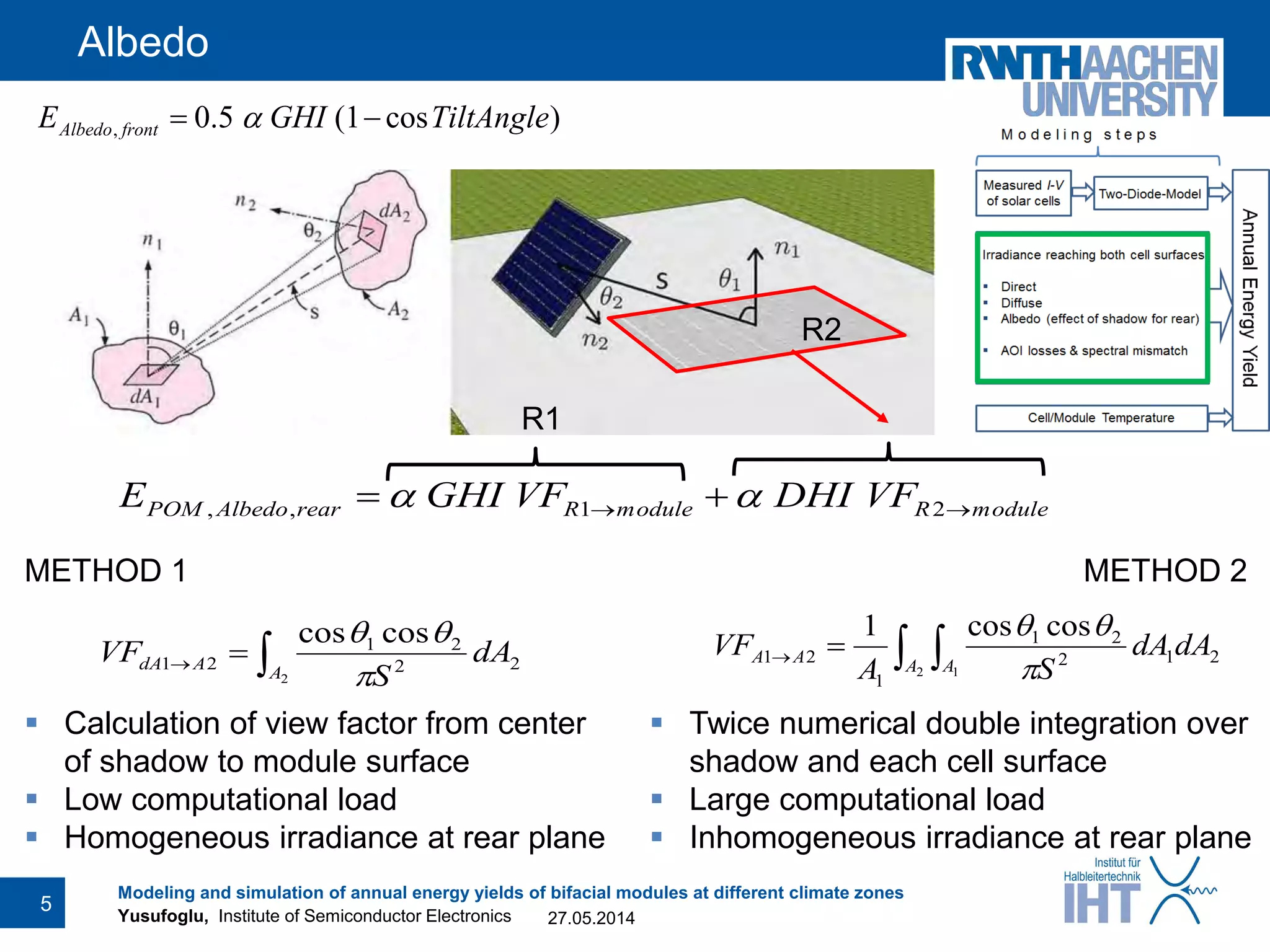
Irradiance at both planes
GHI, DNI, DHI data acquired from GeoModel Solar
with a time resolution of 15 minutes
Three irradiance types separately determined for front/rear
Direct irradiance
– Angle of incidence using azimuth and elevation
– For rear planes of south facing modules mainly insignificant
Diffuse irradiance
– Perez model [1]
Encapsulation losses resolved over angle of incidence via raytracing [2]
Spectral mismatch with King‘s model [3]
[1] Perez et al., Solar Energy 1990; 44(5); 271-289
[2] Tracey, PVLighthouse, http://www.pvlighthouse.com.au/simulation/hosted/tracey/tracey.aspx
[3] King et al., SAND2004-3535
27.05.2014
Modeling and simulation of annual energy yields of bifacial modules at different climate zones
4](https://image.slidesharecdn.com/3-yusufogluok-160401145532/75/3-yusufoglu-ok-4-2048.jpg)
![Yusufoglu, Institute of Semiconductor Electronics
Cell temperature
Time resolved ambient temperature data available
Cell temperature calculation with NOCT formula
𝑇 𝑐𝑒𝑙𝑙 = 𝑇 𝑎𝑚𝑏𝑖𝑒𝑛𝑡 +
𝐼𝑟𝑟𝑎𝑑𝑖𝑎𝑛𝑐𝑒 [𝑊/𝑚2]
800 𝑊/𝑚2
(𝑇𝑁𝑂 𝐶𝑇 − 20 °𝐶)
Standard modules TNOCT = 45 °C
Bifacial modules TNOCT = 47 °C
27.05.2014
Modeling and simulation of annual energy yields of bifacial modules at different climate zones
6](https://image.slidesharecdn.com/3-yusufogluok-160401145532/75/3-yusufoglu-ok-6-2048.jpg)
![Yusufoglu, Institute of Semiconductor Electronics
Locations studied
Two locations with highly different climates
Oslo, Norway:
predominantly diffuse light
higher percentage of low-light
Cairo, Egypt:
predominantly direct light
long time intervals with high insolation
27.05.2014
Modeling and simulation of annual energy yields of bifacial modules at different climate zones
7
0 200 400 600 800 1000
0
200
400
600
800
1000
Frequency[hours/year]
Global horizontal irradiance [W/m2
]
Oslo
Cairo
Constraints in simulations:
Single module operation
smaller shadows than in field
no additional reflection from next row
No soiling/snow
Constant albedo throughout the year](https://image.slidesharecdn.com/3-yusufogluok-160401145532/75/3-yusufoglu-ok-7-2048.jpg)
![Yusufoglu, Institute of Semiconductor Electronics
South facing modules: Tilt angle optimization
27.05.2014
Modeling and simulation of annual energy yields of bifacial modules at different climate zones
8
1397
1402
1208
1213
1088
1093
44 46 48 50 52 54 56 58 60 62
1045
1050
Annualenergyyield[kWh/kWp]
2323
2331
1988
1996
1777
1785
22 24 26 28 30 32 34 36 38 40
1746
1756
α=0.5α=0.2
Oslo Cairo
STD STD
STDSTD
BIF
BIF
BIF
BIF
Tilt angle [°]
α = 0.2 Larger optimal tilt angles for bifacial modules
α = 0.5 Similar optimal tilt angles for both module types
Larger tilt angles for higher reflective ground
[1] Yusufoglu et al., Energy Procedia, in press](https://image.slidesharecdn.com/3-yusufogluok-160401145532/75/3-yusufoglu-ok-8-2048.jpg)
![Yusufoglu, Institute of Semiconductor Electronics
South facing modules: Tilt angle optimization
Larger tilt angles for
– Higher reflective ground
– Lower installations
Changes smaller for Oslo
1.5% yield loss @Cairo α=0.5 h=2m when using θopt = 32° instead of 42°
[1] Yusufoglu et al., Energy Procedia, in press
27.05.2014
Modeling and simulation of annual energy yields of bifacial modules at different climate zones
9
Module
elevation
Oslo Cairo
α = 0.2 α = 0.5 α = 0.2 α = 0.5
2 m 54 56 31 32
0.5 m 54 57 32 34
0 m 55 58 35 42](https://image.slidesharecdn.com/3-yusufogluok-160401145532/75/3-yusufoglu-ok-9-2048.jpg)
![Yusufoglu, Institute of Semiconductor Electronics
Vertically installed modules
Vertically installed modules yield nearly same whether front facing East or West
Provided a high albedo vertical installations can yield more than standard modules
No change in yield with varying module elevation
27.05.2014
Modeling and simulation of annual energy yields of bifacial modules at different climate zones
10
0
300
600
900
1200
1500
Annualenergyyield[kh/kWp
]
STDsouth
BIFsouth
BIFfrontEast
BIFfrontWest
STDsouth
BIFsouth
BIFfrontEast
BIFfrontWest
OSLO
α = 0.2
0
400
800
1200
1600
2000
2400
CAIRO
α = 0.2
STDsouth
BIFsouth
BIFfrontEast
BIFfrontWest
STDsouth
BIFsouth
BIFfrontEast
BIFfrontWest
α = 0.5α = 0.5](https://image.slidesharecdn.com/3-yusufogluok-160401145532/75/3-yusufoglu-ok-10-2048.jpg)
![Yusufoglu, Institute of Semiconductor Electronics
Module elevation & albedo on yield
Annual gain increases with increasing height
– Effect of module elevation small in Oslo less prone to nonoptimal installation
Linear relationship between albedo coefficient and annual yield
– Larger slope for higher installed modules
[1] Yusufoglu et al., Energy Procedia, in press
27.05.2014
Modeling and simulation of annual energy yields of bifacial modules at different climate zones
11
0,20 0,35 0,50
1900
2000
2100
2200
2300
2400
Annualenergyyield[kWh/kWp]
Albedo coefficient
Distance of lower
module edge from ground
2 m
0.5 m
0 m
@ Cairo
1900
2000
2100
2200
2300
2400
0,0 0,5 1,0 1,5 2,0
1210
1214
1304
1308
1398
1404
Cairo
Albedo coefficient 0.5 0.35 0.2
Oslo
Annualenergyyield[kWh/kWp]
Lower module edge from ground [m]](https://image.slidesharecdn.com/3-yusufogluok-160401145532/75/3-yusufoglu-ok-11-2048.jpg)
![Yusufoglu, Institute of Semiconductor Electronics
Comparison with standard modules
Increased yields with bifacial modules than standard ones with
– Higher reflective ground
– Higher installations
Yield gain with higher installations insignificant for Oslo
[1] Yusufoglu et al., Energy Procedia, in press
27.05.2014
Modeling and simulation of annual energy yields of bifacial modules at different climate zones
12
Module
elevation
Oslo Cairo
α = 0.2 α = 0.5 α = 0.2 α = 0.5
2 m 15.5 % 28.3 % 13.8 % 30.6 %
0.5 m 15.5 % 28.3 % 12.9 % 28.8 %
0 m 15.4 % 28.1 % 10.6 % 24.3 %
Bifaciality gain in yield with respect to standard modules](https://image.slidesharecdn.com/3-yusufogluok-160401145532/75/3-yusufoglu-ok-12-2048.jpg)
![Yusufoglu, Institute of Semiconductor Electronics
Inhomogenity at rear module plane
27.05.2014
Modeling and simulation of annual energy yields of bifacial modules at different climate zones
13
Module elevation: 2 m
α = 0.5
Module elevation: 0.1 m
α = 0.5
Irradiance at the module rear side [W/m2] on an examplary summer day in Cairo](https://image.slidesharecdn.com/3-yusufogluok-160401145532/75/3-yusufoglu-ok-13-2048.jpg)

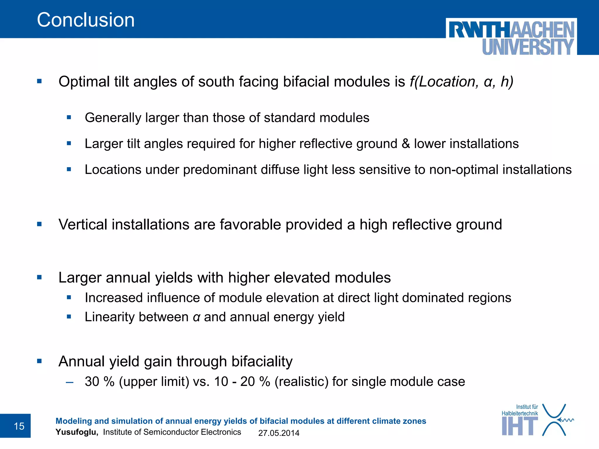

The document discusses the modeling and simulation of annual energy yields of bifacial solar modules across different climate zones, focusing on factors such as tilt angles, module elevation, and albedo. It highlights the performance differences between bifacial and standard modules in locations with predominantly diffuse and direct light, concluding that optimal configurations lead to significant yield gains. The study emphasizes the importance of module installation and environmental conditions in maximizing energy output.


