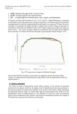
This document discusses optimizing the tilt angle of photovoltaic panels. It begins by providing background on how a panel's tilt angle affects the amount of solar radiation it captures. It then describes the mathematical equations used to calculate the optimal tilt angle based on a location's latitude and the solar declination angle. The document presents experimental results from Iraq that measured the voltage output of panels tilted at different angles. The experimental optimal tilt angle was found to differ from the mathematically calculated angle, demonstrating the need for practical testing to determine the true optimized tilt.
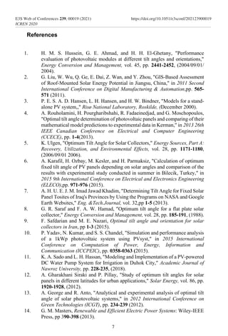
![Photovoltaic panels tilt angle
optimization
Kerry A. Sado,1*
, Lokman H. Hassan 2
, and Shivan Sado3
1
University of Duhok, Electrical and Computer Engineering, Duhok, Kurdistan Region, Iraq.
kherysado@yahoo.com/ kerry.sado@uod.ac
2
University of Duhok, Electrical and Computer Engineering, Duhok, Kurdistan Region, Iraq.
lokman.hadi@uod.ac
3
University of Nebraska-Lincoln, Electrical & Computer Engineering, Lincoln, NE, USA.
shivansado@yahoo.com/ ssado2@unl.edu
Abstract. The tilt angle of solar panels is significant for capturing
solar radiation that reaches the surface of the panel. Photovoltaic
(PV) performance and efficiency are highly affected by its angle of tilt
with respect to the horizontal plane. The amount of radiation reaching
the surface of a PV panel changes with the changes in its tilt angle,
hence adding a solar tracking system will maximize the amount of
solar radiation reaching the surface of a PV panel at any time during
the day, however, integrating solar tracking system will increase the
total cost and maintenance of any PV system. Thus, using an
optimized fixed tilt angle is the solution to element the initial,
maintenance, and operation costs of a solar tracking system. Yet, the
fixed angle is location-specific because it depends on the daily,
monthly, and yearly location of the sun. In this study; daily, monthly
and seasonally angles are calculated mathematically and the amount
of incident radiation on the surface of the PV panel is measured along
with its voltage. By comparing the practical measurements of the
output voltage of PV panels, an optimized tilt angle is decided.
Keywords— Tilt Angle, PV cell, Solar Panel, renewable energy.
1 Introduction
The new modern world is currently moving from conventional energy sources to the clean and
renewable ones. Solar energy has been known as one of the most promising and reliable
renewable energy sources, since it is sustainable and accessible almost everywhere around the
world. One promising application of solar energy is Photovoltaic (PV) technology which has
developed rapidly. Solar PV technology is one of the best methods to harness solar power [1].
The annual solar energy reaching on the surface of the earth is 1.5×10¹⁸ kWh [2], about 30%
of the incoming energy is reflected back to space while the rest is absorbed by oceans, land
masses and clouds. Iraq is located in the Middle East between latitudes 29° 5' and 37° 22' N and
longitudes 38° 45' and 48° 45' E. The highest solar radiation is estimated at 6790kWh/m2 in
September, while the lowest is 1660 kWh/m2 in December [3]. Therefore, Iraq is well located
in terms of solar energy potential.
* Corresponding author: kherysado@yahoo.com/ Kerry.sado@uod.ac
© The Authors, published by EDP Sciences. This is an open access article distributed under the terms of the Creative Commons
Attribution License 4.0 (http://creativecommons.org/licenses/by/4.0/).
E3S Web of Conferences 239, 00019 (2021)
ICREN 2020
https://doi.org/10.1051/e3sconf/202123900019](https://image.slidesharecdn.com/e3sconficren202100019-210415221309/85/Photovoltaic-panels-tilt-angle-optimization-1-320.jpg)
![The performance of PV panels is highly affected by its orientation and tilting angle. The tilt
angle and orientation can change the amount of solar radiation captured by the panel.
Maximum daily energy can be collected by using solar tracking systems also some fixed
systems based on the daily, weekly monthly and seasonally optimized tilt angle at particular
geographical locations. The radiation level reaching the panels depends on the latitude and
longitude of the location where PV panels are located. While sun beams fall with the steep angle
at noon, they fall with a narrow angle in the mornings and afternoon. Hence PV tilt angles varies
depending on the location, and they differ monthly, seasonally and yearly [4]. Monthly and
seasonal changes of tilt angles of panels should be considered by mathematical calculations and
supported by experimental results. Many studies showed that the optimum tilt angle depends on
latitude angle (λ), solar declination angle or days of the year [5]. Researcher in [6] Calculated
the optimum fixed tilt angle of the PV panel in Turkey, they compared the mathematical analysis
results with the experimental results. Their experimental results showed a difference of 11°
between the mathematical and experimental results. Researchers [7] Used Google earth and data
from NASA website to calculate the optimal tilt angle for Iraq provinces, they indicated that the
yearly optimum tilt angle for Duhok is 34.5. Their study did not include a comparison between
mathematical calculations and Google earth results for choosing an optimum tilt angle. In [8],
the authors investigated the effect of various tilt angles on the output of a solar panel in Iraq.
Their study showed that adjusting tilt angle of a PV panel installed in Iraq eight times a year
can capture the same amount of energy as when the tilt angle is adjusted daily. Optimal tilt angle
calculation was mathematically formulated in [9] for finding the optimal tilt angle in Syria. It
was reported that using 12 intervals during a year approximately result in a maximum solar
generation. The rest of the paper is organized as follows: a brief description of tilt angles and
PV panels is provided in section 2; Mathematical equations and calculations of tilt angle are
provided in section 3; the experimental setup and results discussion are provided in section 4;
Section 5 provide results discussion and conclusion.
2 Tilt angles and PV panels
2.1 PV tilt Angle
Solar PV tilt angle is defined as the number of degrees from the horizontal plane [10], another
definition it is slope angle at which solar panels are mounted to face the sun.
The fixed angle is location specific because it depends on the daily, monthly and yearly
location of the sun [11]. [12] Showed that daily changes in tilt angles to their optimum value
in Egypt can reach a total annual gain in solar radiation of 29.2% more than a fixed collector
with a tilt angle equal to its geographic latitude. Yet, daily adjustment of tilt angles is not a
practical solution, due to frequent changes of the angle and composite structure of frames
which support solar panels.
2.2 PV panels
PV panels are semiconductor devices that directly convert the sunlight falling on them to
electrical energy [13]. The efficiency and performance of PV systems are affected by many
factors, such as solar tracking system, shading or partial shading, solar angle, dust, and cell
operating temperature. To achieve maximum output power from PV systems, PV panels
must be installed with a specific orientation and tilt angle with the horizontal plane. The PV
modules are placed facing south in the northern hemisphere as a general rule. A simple
equivalent circuit model for a photovoltaic cell consists of a real diode in parallel with an
ideal current source as shown in Fig. 1. The ideal current source delivers current in
proportion to the solar flux to which it is exposed [14].
2
E3S Web of Conferences 239, 00019 (2021)
ICREN 2020
https://doi.org/10.1051/e3sconf/202123900019](https://image.slidesharecdn.com/e3sconficren202100019-210415221309/85/Photovoltaic-panels-tilt-angle-optimization-2-320.jpg)
![Fig. 1 A simple equivalent circuit for a photovoltaic cell.
2.3 Mathematical equivalent circuit for photovoltaic array
The equivalent circuit of a PV cell is shown in Fig. 2. The current source Iph represents the
cell photocurrent. Rsh and Rs are the intrinsic shunt and series resistances of the cell,
respectively. Generally, the value of Rsh is very large and that of Rs is very small, therefore
they may be neglected to simplify the analysis [15]
Fig. 2 Equivalent PV cell circuit.
Practically, PV cells are grouped in larger units called PV modules and these modules are
connected in series or parallel to create PV arrays which are used to generate electricity in PV
generation systems. The equivalent circuit for PV array is shown in Fig. 3.
Fig. 3 Equivalent circuit of PV array.
The voltage–current characteristic equation of a solar cell is provided as: Module photo-
current Iph:
𝐼𝑝ℎ = [𝐼𝑠𝑐 + 𝐾𝑖(𝑇 − 298)] × 𝐼𝑟/1000 (1)
Where, Iph: photo-current (A); Isc: short circuit current (A); Ki: short-circuit current of cell at
25 °C and 1000 W/m2; T: operating temperature (K); Ir: solar irradiation (W/m2).
The reverse saturation current of the module 𝐼𝑟𝑠:
𝐼𝑟𝑠 = 𝐼𝑠𝑐/[exp(𝑞𝑉𝑂𝐶/𝑁𝑆𝑘𝑛𝑇) − 1] (2)
3
E3S Web of Conferences 239, 00019 (2021)
ICREN 2020
https://doi.org/10.1051/e3sconf/202123900019](https://image.slidesharecdn.com/e3sconficren202100019-210415221309/85/Photovoltaic-panels-tilt-angle-optimization-3-320.jpg)
![Where, q: electron charge, = 1.6 × 10⁻¹⁹C; Voc: open circuit voltage (V); Ns: number of cells
connected in series; n: the ideality factor of the diode; k: Boltzmann’s
constant, = 1.3805 × 10⁻²³ J/K. With cell`s temperature variation, the saturation current I0 is
given by:
𝐼0 = 𝐼𝑟𝑠 [
𝑇
𝑇𝑟
]
3
exp [
𝑞×𝐸𝑔0
𝑛𝑘
(
1
𝑇
−
1
𝑇𝑟
)] (3)
Where, Tr: nominal temperature = 298.15 K; Eg0: band gap energy of the semiconductor, =
1.1 eV; The current output of PV module is:
𝐼 = 𝑁𝑃 × 𝐼𝑝ℎ − 𝑁𝑃 × 𝐼0
× [exp (
𝑉/𝑁𝑆+𝐼×𝑅𝑠/𝑁𝑃
𝑛×𝑉𝑡
) − 1] − 𝐼𝑠ℎ
(4)
𝑉𝑡 =
𝑘×𝑇
𝑞
and 𝐼𝑠ℎ =
𝑉×𝑁𝑃/𝑁𝑆+𝐼×𝑅𝑆
𝑅𝑠ℎ
Where: Np: number of PV modules connected in parallel; Rs: series resistance (Ω); Rsh: shunt
resistance (Ω); Vt: diode thermal voltage (V).
3 MATHEMATICAL CALCULATION OF TILT ANGLE
The earth orbits the sun in an elliptical way, making one revolution every 365.25 days. For
solar energy applications, the characteristics of the earth’s orbit are considered to be
unchanging [14]. It is known that the sun rises in the east and sets in the west and reaches its
highest point sometime in the noon. As shown in Fig. 4, the angle formed between the plane
of the equator and a line drawn from the center of the sun to the center of the earth is called
the solar declination δ [14].
On June 21 (the summer solstice) the sun reaches its highest point, and a ray drawn at that time
from the center of the sun to the center of the earth makes an angle of 23.45◦ with the On June
21 (the summer solstice) the sun reaches its highest point, and a ray drawn at that time from the
center of the sun to the center of the earth makes an angle of 23.45◦ with the earth’s equator. On
that day, the sun is directly over the Tropic of Cancer at latitude 23.45◦. At the two equinoxes,
the sun is directly over the equator. On December 21 the sun is 23.45◦ below the equator, which
defines the latitude known as the Tropic of Capricorn. Calculation of the optimal tilt angle of a
PV panel requires an understanding of the declination angle of the earth. Declination angle
varies between the extremes of ± 23.45◦, and a simple sinusoidal relationship that assumes a
365-day year and which puts the spring equinox on day n = 81 provides a very good
approximation. Declination angle is calculated by the following equation.
δ = 23.45°sin[
360
365
(n − 81)] (5)
Where n is the nth day of the year, for example, the January 1st
is 1.
Fig. 4 An alternative view with a fixed earth and a sun that moves up and down. The angle
between the sun and the equator is called the solar declination δ [14].
4
E3S Web of Conferences 239, 00019 (2021)
ICREN 2020
https://doi.org/10.1051/e3sconf/202123900019](https://image.slidesharecdn.com/e3sconficren202100019-210415221309/85/Photovoltaic-panels-tilt-angle-optimization-4-320.jpg)
![The altitude angle is calculated as:
𝛽𝑁 = 90° − 𝐿 + 𝛿 (6)
where L is the latitude of the site. The tilt angle that is given by:
Tilt(∅) = 90° − 𝛽𝑁 (7)
Equations (5-7) are used to calculate the declination angle and tilt angle for solar PV modules
for each day of the year [15]. Using equation (5-7), the tilt angle of the first day of each
month in a year for Duhok city written in the Matlab program using the formulas about solar
angles is shown in Fig. 5.
Fig. 5 Monthly tilt angles for Duhok city
The monthly optimum fixed tilt angles are shown in Table 1.
Table 1: Monthly Optimum Tilt Angle
Jan Feb Mar Apr May Jun
57.7° 50.18° 39.24° 27.36° 18.0° 13.78°
Jul Aug Sep Oct Nov Dec
15.75° 23.56° 34.46° 46.7° 55.9° 55.95°
For maximum efficiency and practical use of fixed tilt angle, the optimum fixed tilt angle is
calculated on monthly basis. The yearly tilt angle for Duhok city is calculated at 36.88° which
is nearly equal to the latitude of the city [16].
4 EXPERIMENTAL METHODOLOGY
In this study, three identical 100 W monocrystalline PV panels are used. Each panel is able to
produce maximum power (Pmax) of 100 watts at standard conditions (STC) (i.e., temperature
25° C, 1000 watts/m2 of solar insolation and air mass of 1.5). However, in Iraq the operating
temperatures during the summer are usually higher than STC. PV panels operating at
temperatures higher than 25° C produce less than their rated power. Thus, the efficiency of PV
panels drops below the rated values. These modules can produce a voltage (Vmp) and current
(Imp) of 16.7 volts and 3.0 amps with an efficiency of 13.5 % at STC. The open circuit voltage
(Voc) and short-circuit current (Isc) of each module are 21.1 V and 3.20 A respectively. Three
different tilt angles are calculated mathematically using (5-7):
0
10
20
30
40
50
60
70
Angle
(Deg)
Month of the year
Monthly tilt angle for Duhok city
5
E3S Web of Conferences 239, 00019 (2021)
ICREN 2020
https://doi.org/10.1051/e3sconf/202123900019](https://image.slidesharecdn.com/e3sconficren202100019-210415221309/85/Photovoltaic-panels-tilt-angle-optimization-5-320.jpg)