
Download as PDF, PPTX


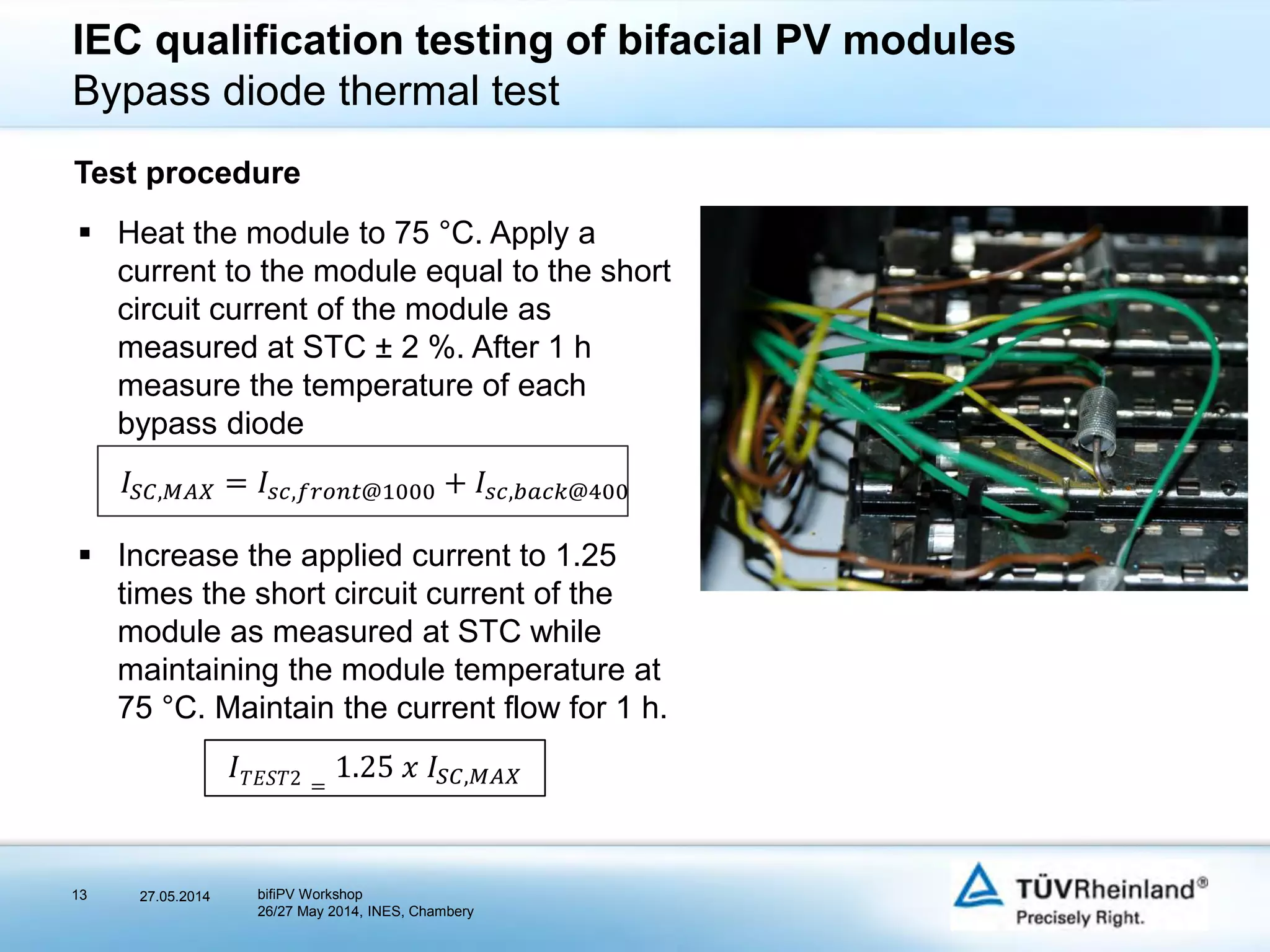


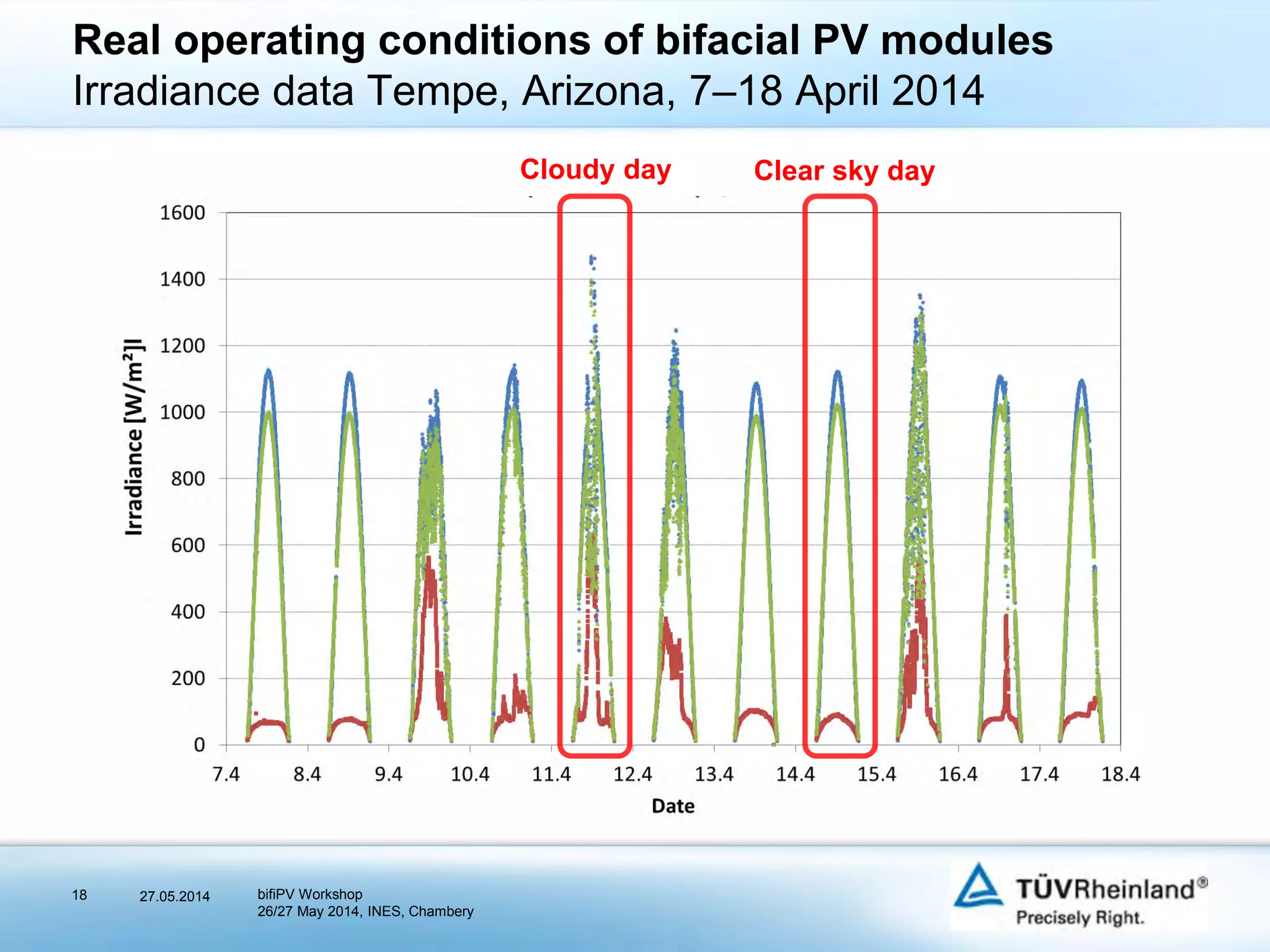

1) IEC qualification testing standards can be applied to bifacial PV modules with some modifications to test conditions that involve module current levels. Specifically, thermal cycling, hot spot, and bypass diode thermal tests need to set the test current based on the maximum total module short circuit current. 2) Maximum total module current is calculated by adding the short circuit current from 1000 W/m2 front side irradiation and 400 W/m2 rear side irradiation. Simulation studies have confirmed rear side irradiance can reach 400 W/m2 under real operating conditions. 3) Power rating for bifacial modules should refer only to front side power output, with rear side output provided as additional information.


