Download to read offline
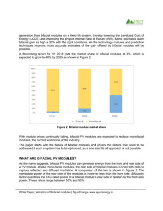


The white paper discusses the rising adoption of bifacial photovoltaic (PV) modules, highlighting their advantages over traditional monofacial modules, primarily due to improved efficiency and decreasing costs. Key factors for optimal performance include site conditions, module design, and the use of tracking systems to enhance energy generation by capturing reflected light. The paper also addresses current challenges in measuring the performance of bifacial modules and notes anticipated growth in market share from 3% to 40% by 2025.


