
Download as PDF, PPTX

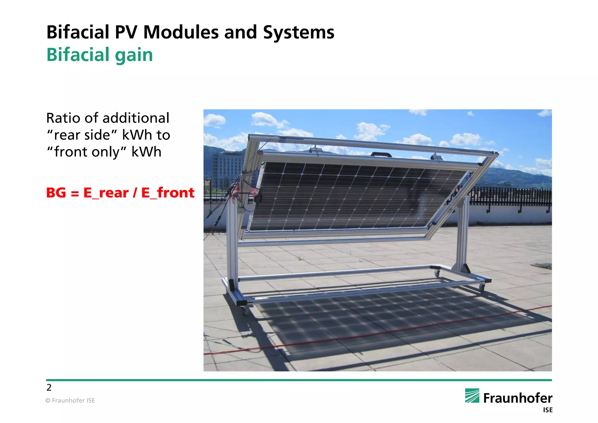
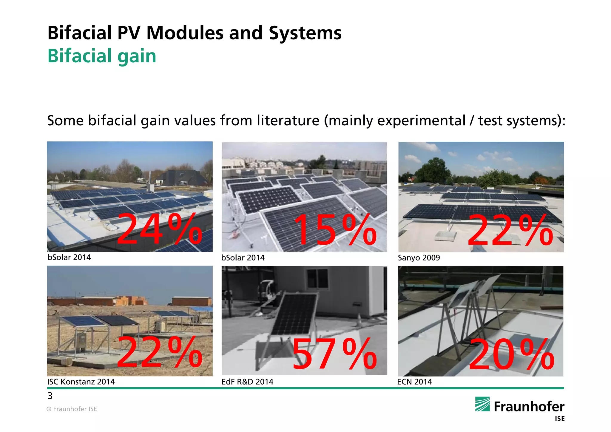
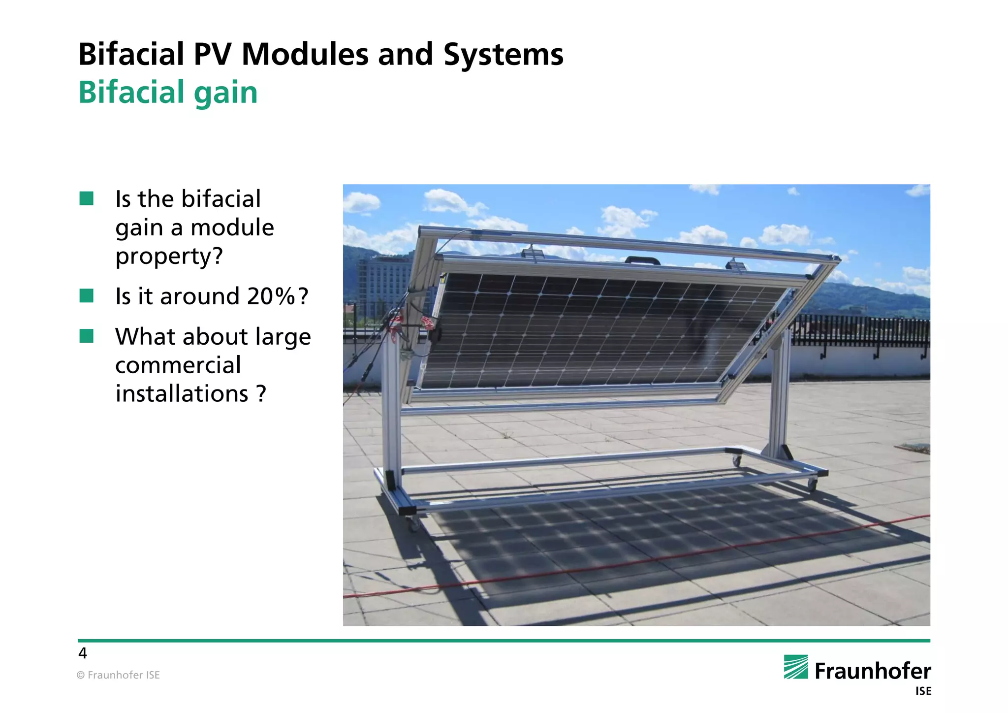


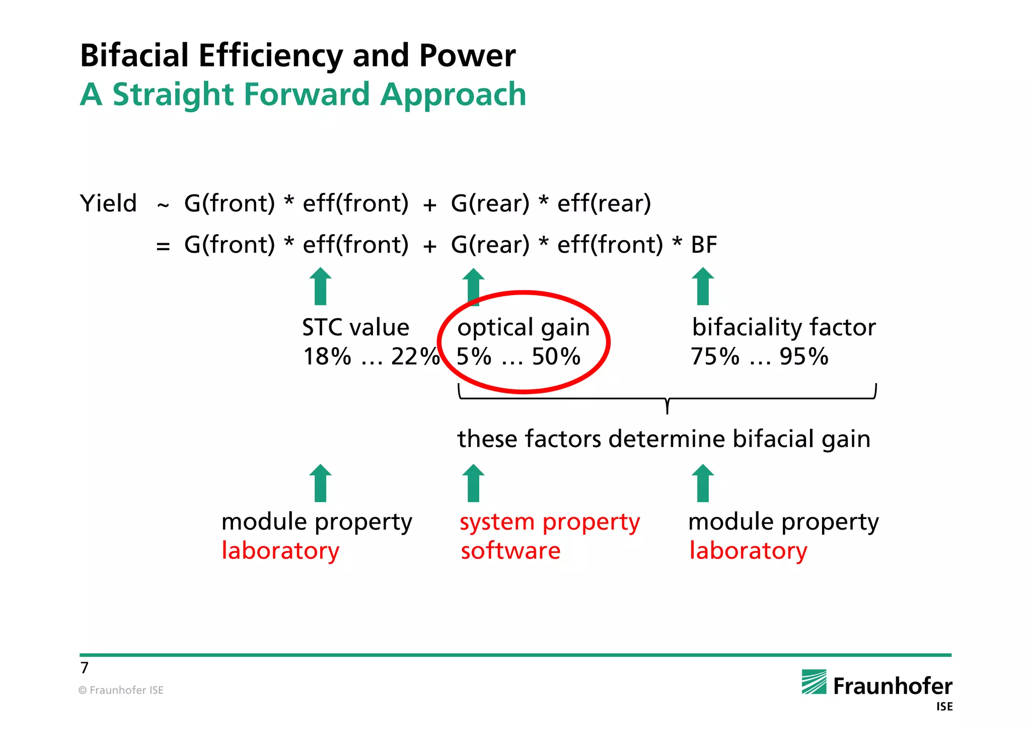


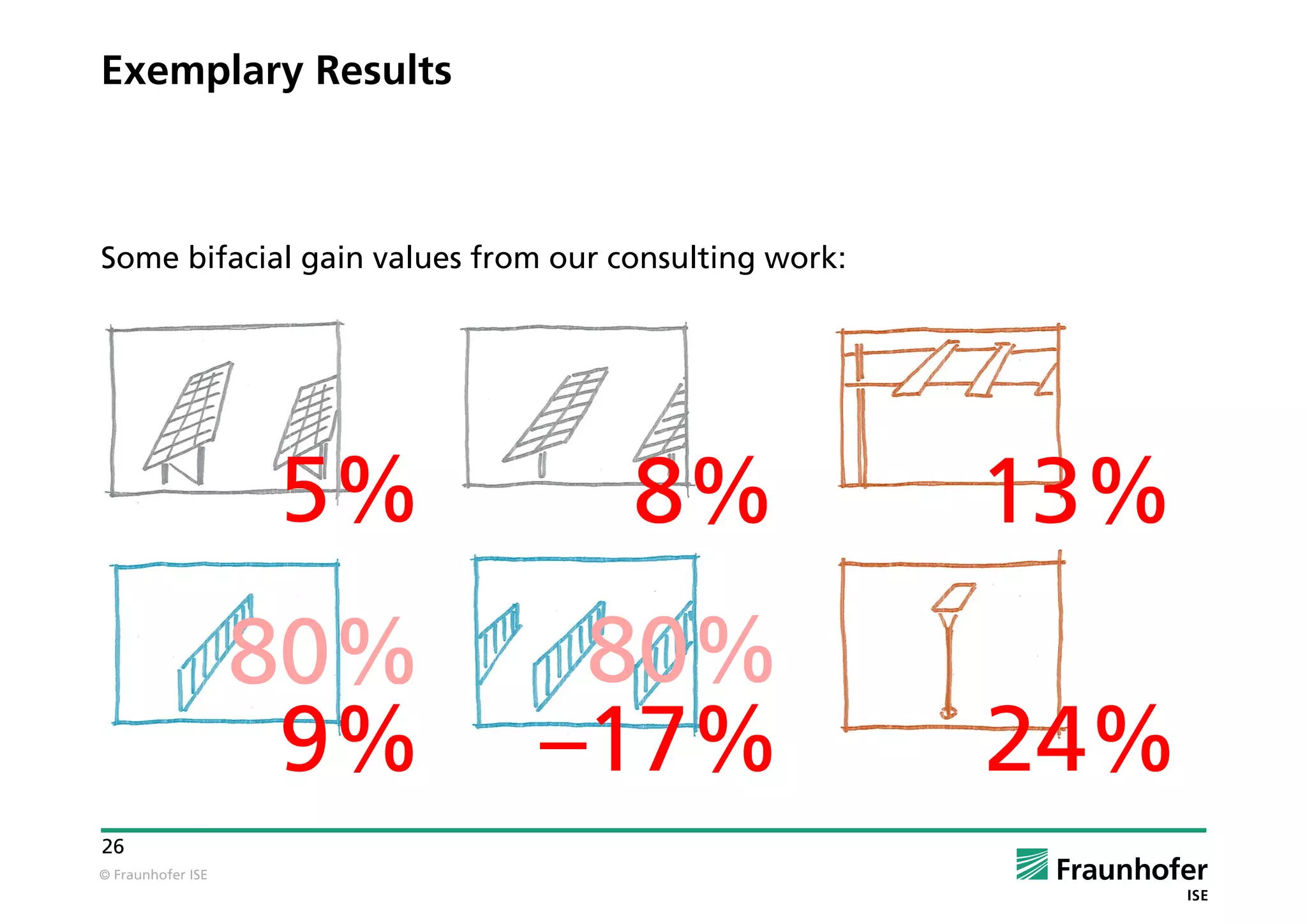


The document assesses the performance and yield expectations of bifacial photovoltaic (PV) systems, highlighting their potential benefits compared to traditional monofacial modules. Bifacial gain, defined as the additional energy harvested from the rear side of bifacial modules, varies significantly based on multiple factors, with experimental systems showing gains of 15% to 25% but realistic commercial installations expected to yield between 5% to 15%. Effective optimization of module placement and mounting structure is crucial for maximizing the benefits of bifacial technology.


