Downloaded 13 times
![Concept Kit
Modeling of 3-Phase AC Motor
Drive Simulation
For Electric Drive Systems
[PSpice Version]
All Rights Reserved Copyright (C) Bee Technologies Inc. 2012 1](https://image.slidesharecdn.com/3-phaseacmotormodelpsspiceopen-120913030034-phpapp02/85/Concept-Kit-3-Phase-AC-Motor-Drive-Simulation-PSpice-Version-1-320.jpg)
![Concept Kit
Modeling of 3-Phase AC Motor
Drive Simulation
For Electric Drive Systems
[PSpice Version]
All Rights Reserved Copyright (C) Bee Technologies Inc. 2012 1](https://image.slidesharecdn.com/3-phaseacmotormodelpsspiceopen-120913030034-phpapp02/75/Concept-Kit-3-Phase-AC-Motor-Drive-Simulation-PSpice-Version-1-2048.jpg)
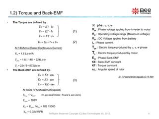
![1.5) Parameters Settings
Model Parameters:
LOAD : Load current each phase of motor [Arms]
U 1 – e.g. LL = 125Arms, 140Arms, or 400Arms
M E0913
1
LL : Phase inductance [H]
LL = 105U
M
– e.g. LL = 10mH, 100mH, or 1H
2 4 R L L = 0 .0 1 2 5
N 0 KE = 0 .0 2
3 KT = 1 .6 RLL : Phase resistance (Phase-to-phase) [Ω]
LO AD = 140 – e.g. RLL = 10mΩ, 100mΩ, or 1Ω
KE : Back-EMF constant [V/RPM]
– e.g. KE= 0.01, 0.05, or 0.1
Fig. 4 Symbol of 3-Phase Induction Motor KT : Torque constant [Lb-in/A]
– e.g. KT= 0.1, 0.5, or 1
1 Pound Inch equals 0.11 Nm
• From the 3-Phase Induction Motor specification, the model is characterized by setting parameters
LL, RLL, KE, KT and LOAD.
All Rights Reserved Copyright (C) Bee Technologies Inc. 2012 7](https://image.slidesharecdn.com/3-phaseacmotormodelpsspiceopen-120913030034-phpapp02/85/Concept-Kit-3-Phase-AC-Motor-Drive-Simulation-PSpice-Version-7-320.jpg)
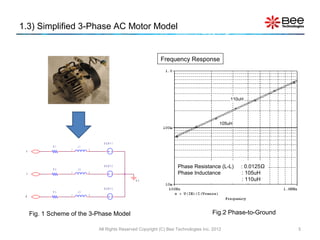
![2.4) Power Output and Efficiency Characteristics At 140Arms
- Simulation Results
2 0 KW
At Load=140Arms, Power Output ≈ 13.7 [KW]
( 9 6 0 . 6 1 6 m, 1 3 . 6 6 2 K)
Watt 1 0 KW
SEL > >
0W
RMS( V( RU: 1 , N0 ) ) * RMS( I ( RU) )
100
At Load=140Arms, Efficiency ≈ 82 [%]
( 9 6 2 . 5 0 0 m, 8 1 . 9 4 1 )
[%] 50
0
0. 5s 1. 0s
100* ( ( RMS( V( U, N0 ) ) * RMS( I ( RU) ) ) / ( RMS( V( RU: 1 , N0 ) ) * RMS( I ( RU) ) ) )
Ti me Reference of Phase U
Fig. 9 Power Output and Efficiency Characteristics at Load=140Arms
All Rights Reserved Copyright (C) Bee Technologies Inc. 2012 12](https://image.slidesharecdn.com/3-phaseacmotormodelpsspiceopen-120913030034-phpapp02/85/Concept-Kit-3-Phase-AC-Motor-Drive-Simulation-PSpice-Version-12-320.jpg)

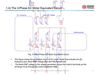
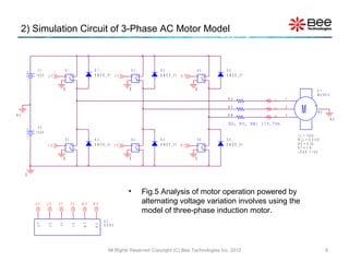
This document provides information about modeling a 3-phase AC motor for electric drive system simulation in PSpice. It includes the motor specifications, modeling of torque and back-EMF, a simplified 3-phase AC motor model, the equivalent circuit model, and parameter settings. Appendices provide details on measuring points, evaluation text, gate signals, model text, and simulation settings.


