Downloaded 28 times
![Concept Kit
3-Phase AC Motor
Drive Simulation
For Electric Drive Systems
[LTspice Version]
All Rights Reserved Copyright (C) Bee Technologies Inc. 2012 1](https://image.slidesharecdn.com/3-phaseacmotormodelltspiceopen-120912011139-phpapp02/85/Concept-Kit-3-Phase-AC-Motor-Drive-Circuit-Simulation-LTspice-Version-1-320.jpg)
![Concept Kit
3-Phase AC Motor
Drive Simulation
For Electric Drive Systems
[LTspice Version]
All Rights Reserved Copyright (C) Bee Technologies Inc. 2012 1](https://image.slidesharecdn.com/3-phaseacmotormodelltspiceopen-120912011139-phpapp02/75/Concept-Kit-3-Phase-AC-Motor-Drive-Circuit-Simulation-LTspice-Version-1-2048.jpg)
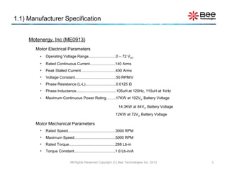
![1.5) Parameters Settings
Model Parameters:
LOAD : Load current each phase of motor [Arms]
– e.g. LL = 125Arms, 140Arms, or 400Arms
LL : Phase inductance [H]
– e.g. LL = 10mH, 100mH, or 1H
RLL : Phase resistance (Phase-to-phase) [Ω]
– e.g. RLL = 10mΩ, 100mΩ, or 1Ω
KE : Back-EMF constant [V/RPM]
– e.g. KE= 0.01, 0.05, or 0.1
Fig. 4 Symbol of 3-Phase Induction Motor KT : Torque constant [Lb-in/A]
– e.g. KT= 0.1, 0.5, or 1
1 Pound Inch equals 0.11 Nm
• From the 3-Phase Induction Motor specification, the model is characterized by setting parameters
LL, RLL, KE, KT and LOAD.
All Rights Reserved Copyright (C) Bee Technologies Inc. 2012 7](https://image.slidesharecdn.com/3-phaseacmotormodelltspiceopen-120912011139-phpapp02/85/Concept-Kit-3-Phase-AC-Motor-Drive-Circuit-Simulation-LTspice-Version-7-320.jpg)
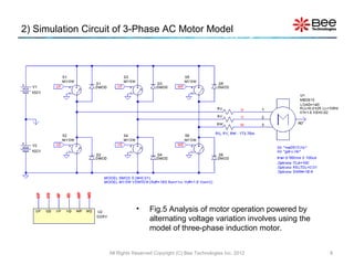
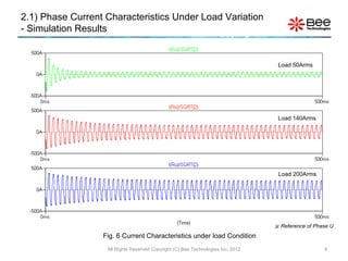
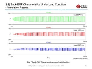
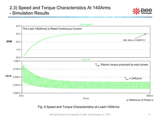

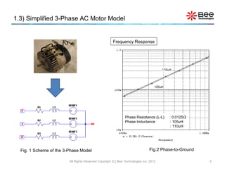
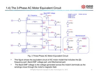
This document provides a model and simulation of a 3-phase AC motor. It includes specifications for a Motenergy ME0913 motor and defines the torque, back-EMF, and equivalent circuit model. Simulation results show characteristics of phase current, back-EMF, speed and torque under varying load conditions. The model and simulation analyze motor operation powered by alternating voltage variations.