Download to read offline

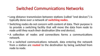
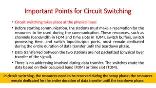
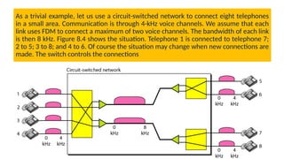
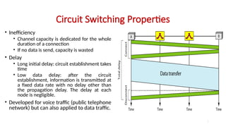
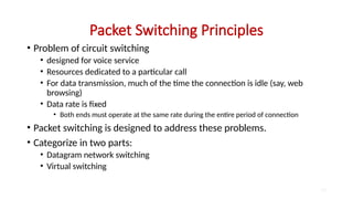
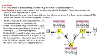
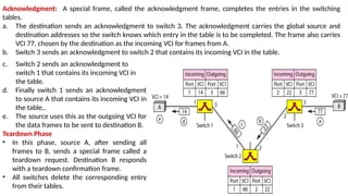

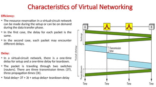
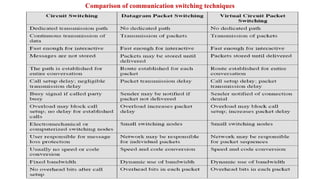

The document covers the principles of circuit switching and packet switching in communication networks. Circuit switching establishes a dedicated communication path for the entire duration of a connection, while packet switching divides data into packets that can be transmitted independently without reservation of resources. It also discusses virtual-circuit networks, which combine aspects of both techniques, including setup and teardown phases along with dynamic resource allocation.