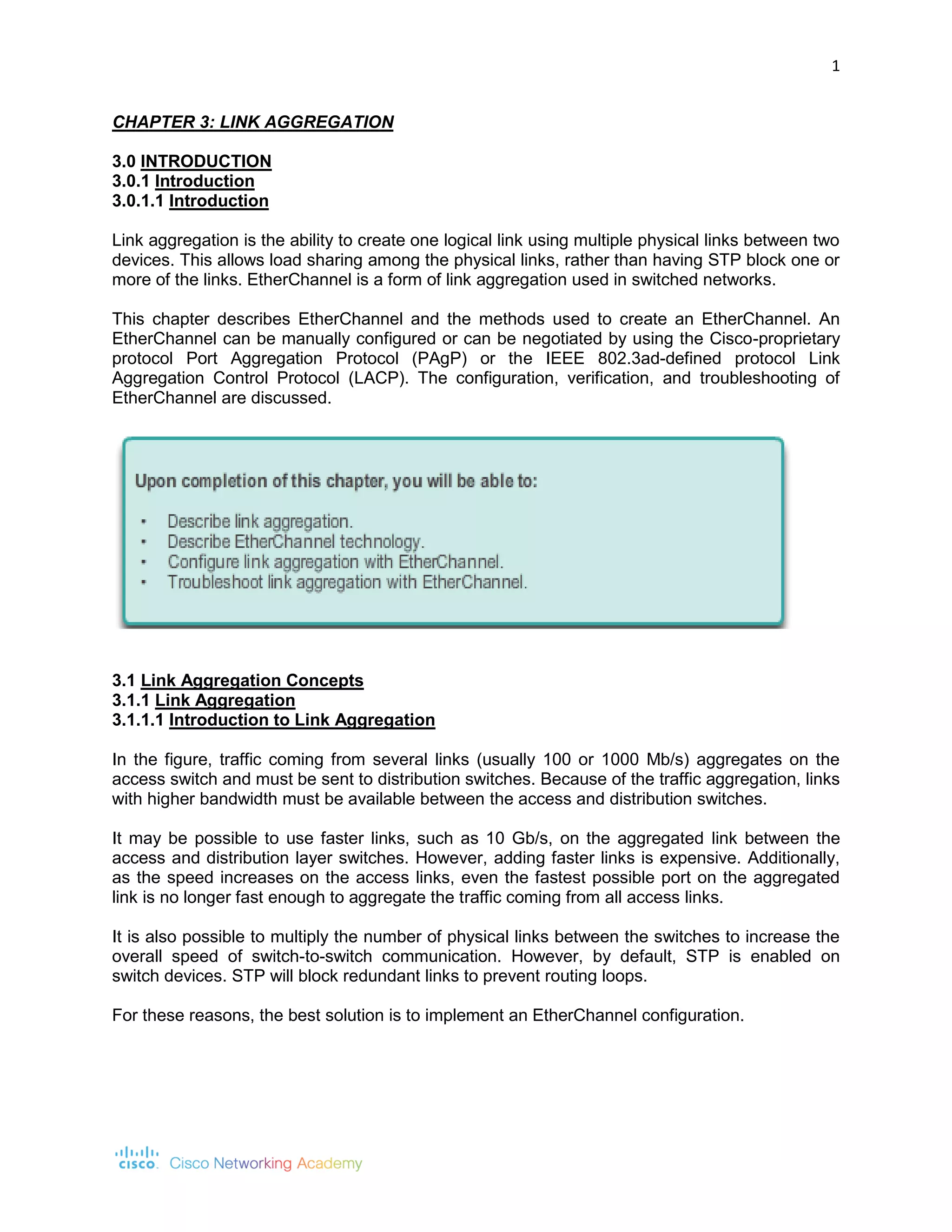
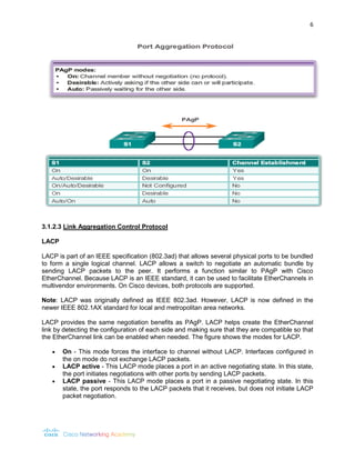
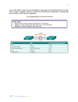
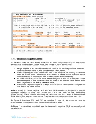
EtherChannel aggregates multiple physical links between two devices into a single logical trunk to increase bandwidth and provide link redundancy. It uses either the Cisco proprietary PAgP protocol or the IEEE standard LACP protocol to automatically negotiate the creation of EtherChannel links. Key requirements for EtherChannel include all ports having the same speed, duplex, and VLAN configuration. The show commands can be used to verify and troubleshoot EtherChannel configurations.
Basic interview question for Ether Channel.INFitunes
In this slide determine about Defination of ether channel,
1. Why Ether channel used for ?
2. How many port on ether channel ?
3. How many channel can be created on ether channel?
4. Is that works as a redundancy ?
5. Advantage of ether channel and Protocols like static , Lacp(Link aggregation control protocol). pagp(port aggregation protocol),On (for static.)
It prevents a network from frame looping by putting some interfaces in forwarding state & some
interfaces in blocking state.
Whenever two or more switches are connected with each other for redundancy purpose loop can occur.
STP Protocol is used to prevent the loop. STP is layer 2 Protocol & by default it is enabled on switches.
Difference between Spanning Tree Protocol (STP) and Rapid Spanning Tree
Protocol (RSTP)
1. The main difference between Rapid Spanning Tree Protocol (RSTP IEEE 802.1W) and Spanning
Tree Protocol (STP IEEE 802.1D) is that Rapid Spanning Tree Protocol (RSTP IEEE 802.1W)
assumes the three Spanning Tree Protocol (STP) ports states Listening, Blocking, and Disabled are
same (these states do not forward Ethernet frames and they do not learn MAC addresses).
Hence Rapid Spanning Tree Protocol (RSTP IEEE 802.1W) places them all into a new called
Discarding state. Learning and forwarding ports remain more or less the same.
Ether Channel High Speed Data TransmissionNetwax Lab
EtherChannel is a port link aggregation technology or port-channel architecture used primarily on Cisco
switches. It allows grouping of several physical Ethernet links to create one logical Ethernet link for the
purpose of providing fault-tolerance and high-speed links between switches, routers and servers. An
EtherChannel can be created from between two and eight active Fast, Gigabit or 10-Gigabit Ethernet
ports, with an additional one to eight inactive (failover) ports which become active as the other active
ports fail. EtherChannel is primarily used in the backbone network, but can also be used to connect end
user machines.
How to Connect Multiple Ethernet Switches : NotesSubhajit Sahu
Highlighted notes while studying the Course:
Advanced Computer Networks
Article: An Introduction to Network Switches
By: Jason, FS Community
FS is a global leading communications hardware and project solutions provider. They are dedicated to helping build, connect, protect and optimize optical infrastructure.
Config Lab L2 EtherChannel 2 Both layer 2 EtherChannel and layer 3 Eth.pdf21stcenturyjammu21
Config Lab L2 EtherChannel 2 Both layer 2 EtherChannel and layer 3 EtherChannel use the
same set of commands to create the channel. You have the option to use static configuration or
one of two dynamic protocols to negotiate the formation of a trunk (LACP or PAgP). Today's lab
provides a little exercise on all three options (static, PAgP, LACP) in the context of L2
EtherChannels, but it helps you prepare for both L2 and L3 EtherChannel configuration. The Lab
Exercise Requirements This lab uses a small LAN, all acting as layer 2 switches. Several pairs of
switches connect with a pair of links that operate as 802.1 Q trunks. Your job: make each pair of
links operate as a layer 2 EtherChannel. As a bit of a twist, the initial configuration for this lab
pre-configures some details. Your job is to determine the correct configuration that should be
added to the initial configuration. By starting out with some configuration, you not only have to
think about a nice orderly configuration, but also the impacts of the existing configuration on the
final EtherChannel configuration. The specific rules for this lab are: - Configure the three
EtherChannels shown in the figure as follows: - Dist 1 - Dist 2: manually configured. - Dist 1 -
Access 1: Use LACP, with Dist1 initiating the negotiations and Access 1 not initiating the
negotiations. - Dist2 - Access 2: Use PAgP, with Dist2 initiating the negotiations and Access2
not initiating the negotiations. - All physical links between switches already use 802.1 Q
trunking per the initial configurations. - Ensure that the Port Channels act as trunks: - Use 802.1
Q trunking instead of ISL. - Configure all switches to dynamically negotiate trunking, and all
switches to initiate that negotiation. - All physical links between switches already use 802.1Q
trunking per the initial configurations. - Ensure that the Port Channels act as trunks: - Use
802.1Q trunking instead of ISL. - Configure all switches to dynamically negotiate trunking, and
all switches to initiate that negotiation. Figure 1: Distribution/Access Switch Topology Initial
Configuration Examples 1, 2, 3, and 4 show the beginning configuration state of Dist1, Dist2,
Access1, and Access2. hostname Distl ! vlan 2 , 3 , 4 interface GigabitEthernet1/0/1 switchport
trunk encapsulation dotlq switchport mode dynamic desirable channel-group 10 mode on !
interface GigabitEthernet1/0/2 switchport access vlan 2 switchport trunk encapsulation dotlq
switchport mode dynamic desirable channel-group 10 mode on ! interface GigabitEthernet1/0/3
switchport trunk encapsulation dotlq switchport mode dynamic desirable channel-group 20 mode
active ! interface GigabitEthernet1/0/4 switchport trunk encapsulation dotlq switchport mode
dynamic desirable channel-group 20 mode active Example 1: Dist1 Config hostname Dist 2 !
vlan 2 , 3 , 4 ! interface GigabitEthernet 1/0/1 switchport trunk encapsulation dotlq switchport
mode dynamic desirable channel-group 10 mode on ! interface Giga.
RRSTP: A Spanning Tree Protocol for Obviating Count-to-Infinity from Switched...CSCJournals
This paper will presents a highly reliable and rapidly converging spanning tree protocol named as Reliable Rapid Spanning Tree Protocol. The need of this spanning tree protocol is felt because reliability of switched Ethernet networks is heavily dependent upon that of spanning tree protocol. But current standard spanning tree protocol – Rapid Spanning Tree Protocol – is well known for its susceptibility to classical count-to-infinity problem. Because of this problem the protocol has extremely variable and unexpectedly high convergence time even in small networks. As a result network wide congestion, frame loss and frame delay may occur. Even forwarding loops may be induced into the network under certain circumstances. It is expected that the new protocol – RRSTP – will significantly increase the dependability of switched Ethernet networks by providing guaranteed protection against the count-to-infinity problem.
Link Aggregation Control Protocol on Software Defined Network IJECEIAES
A physical connection of computer network must be made reliably. Breaking connection will cause communication between nodes (for example routers, switches, hosts) can be disconnected. One of the solutions is implemention of link aggregation (LA). LA integrates several of physical ports together to make a single logical communication link. Accordingly, there is load sharing traffic among the member port of the group, high-throughput increasing via a single link, and redundancy providing for broken links. We present the implementation of link aggregation using Ryu controller on Software Defined Network (SDN) topology. The results show that the implementation of SDN with OpenvSwitch and Ryu controller can successfully run link aggregation function to solve the problem of link failure.
Local Restoration in Metro Ethernet Networks for Multiple Link FailuresEditor IJCATR
Ethernet a popular choice for metropolitan-area networks (MAN) due to simplicity, cost effectiveness and scalability. The
Spanning-Tree based switching mechanism, which is considered to be very efficient at avoiding switching loops in LAN environment,
is a performance bottleneck in Metro network context. Handling of link failure is an important issue in metro Ethernet networks. A
link failure may result in serious service disruptions. A local restoration method for metro Ethernet with multiple spanning trees, which
aims at fast handling of single link failures in a distributed manner, have been proposed in the literature. In this paper, we propose a
local restoration mechanism that uses MULTILINK algorithm for solving multiple link failures
Traffic engineering is one of the major issues that has to be addressed in Metro Ethernet networks for quality of service and efficient resource utilization. This paper aims at understanding the relevant issues and outlines novel algorithms for multipoint traffic engineering in Metro Ethernet. We present an algorithmic solution for traffic engineering in Metro Ethernet using optimal multiple spanning trees. This iterative approach distributes traffic across the network uniformly without overloading network resources. We also introduce a new traffic specification model for Metro Ethernet, which is a hybrid of two widely used traffic specification models, the pipe and hose models.
The Avaya VENA Fabric Connect solution is based on the IEEE 802.1aq Shortest Path Bridging (SPB) protocol in conjunction with Avaya extensions that add Layer 3 routing capabilities to SPB functionality. The Fabric Connect solution has a range of features that can greatly simplify network operations and at the same time enhance the network’s ability to provide the appropriate level of service for business critical applications.
GraphRAG is All You need? LLM & Knowledge GraphGuy Korland
Guy Korland, CEO and Co-founder of FalkorDB, will review two articles on the integration of language models with knowledge graphs.
1. Unifying Large Language Models and Knowledge Graphs: A Roadmap.
https://arxiv.org/abs/2306.08302
2. Microsoft Research's GraphRAG paper and a review paper on various uses of knowledge graphs:
https://www.microsoft.com/en-us/research/blog/graphrag-unlocking-llm-discovery-on-narrative-private-data/
Transcript: Selling digital books in 2024: Insights from industry leaders - T...BookNet Canada
The publishing industry has been selling digital audiobooks and ebooks for over a decade and has found its groove. What’s changed? What has stayed the same? Where do we go from here? Join a group of leading sales peers from across the industry for a conversation about the lessons learned since the popularization of digital books, best practices, digital book supply chain management, and more.
Link to video recording: https://bnctechforum.ca/sessions/selling-digital-books-in-2024-insights-from-industry-leaders/
Presented by BookNet Canada on May 28, 2024, with support from the Department of Canadian Heritage.
Neuro-symbolic is not enough, we need neuro-*semantic*Frank van Harmelen
Neuro-symbolic (NeSy) AI is on the rise. However, simply machine learning on just any symbolic structure is not sufficient to really harvest the gains of NeSy. These will only be gained when the symbolic structures have an actual semantics. I give an operational definition of semantics as “predictable inference”.
All of this illustrated with link prediction over knowledge graphs, but the argument is general.
Search and Society: Reimagining Information Access for Radical FuturesBhaskar Mitra
The field of Information retrieval (IR) is currently undergoing a transformative shift, at least partly due to the emerging applications of generative AI to information access. In this talk, we will deliberate on the sociotechnical implications of generative AI for information access. We will argue that there is both a critical necessity and an exciting opportunity for the IR community to re-center our research agendas on societal needs while dismantling the artificial separation between the work on fairness, accountability, transparency, and ethics in IR and the rest of IR research. Instead of adopting a reactionary strategy of trying to mitigate potential social harms from emerging technologies, the community should aim to proactively set the research agenda for the kinds of systems we should build inspired by diverse explicitly stated sociotechnical imaginaries. The sociotechnical imaginaries that underpin the design and development of information access technologies needs to be explicitly articulated, and we need to develop theories of change in context of these diverse perspectives. Our guiding future imaginaries must be informed by other academic fields, such as democratic theory and critical theory, and should be co-developed with social science scholars, legal scholars, civil rights and social justice activists, and artists, among others.
Let's dive deeper into the world of ODC! Ricardo Alves (OutSystems) will join us to tell all about the new Data Fabric. After that, Sezen de Bruijn (OutSystems) will get into the details on how to best design a sturdy architecture within ODC.
Smart TV Buyer Insights Survey 2024 by 91mobiles.pdf91mobiles
91mobiles recently conducted a Smart TV Buyer Insights Survey in which we asked over 3,000 respondents about the TV they own, aspects they look at on a new TV, and their TV buying preferences.
JMeter webinar - integration with InfluxDB and GrafanaRTTS
Watch this recorded webinar about real-time monitoring of application performance. See how to integrate Apache JMeter, the open-source leader in performance testing, with InfluxDB, the open-source time-series database, and Grafana, the open-source analytics and visualization application.
In this webinar, we will review the benefits of leveraging InfluxDB and Grafana when executing load tests and demonstrate how these tools are used to visualize performance metrics.
Length: 30 minutes
Session Overview
-------------------------------------------
During this webinar, we will cover the following topics while demonstrating the integrations of JMeter, InfluxDB and Grafana:
- What out-of-the-box solutions are available for real-time monitoring JMeter tests?
- What are the benefits of integrating InfluxDB and Grafana into the load testing stack?
- Which features are provided by Grafana?
- Demonstration of InfluxDB and Grafana using a practice web application
To view the webinar recording, go to:
https://www.rttsweb.com/jmeter-integration-webinar
PHP Frameworks: I want to break free (IPC Berlin 2024)Ralf Eggert
In this presentation, we examine the challenges and limitations of relying too heavily on PHP frameworks in web development. We discuss the history of PHP and its frameworks to understand how this dependence has evolved. The focus will be on providing concrete tips and strategies to reduce reliance on these frameworks, based on real-world examples and practical considerations. The goal is to equip developers with the skills and knowledge to create more flexible and future-proof web applications. We'll explore the importance of maintaining autonomy in a rapidly changing tech landscape and how to make informed decisions in PHP development.
This talk is aimed at encouraging a more independent approach to using PHP frameworks, moving towards a more flexible and future-proof approach to PHP development.
UiPath Test Automation using UiPath Test Suite series, part 3DianaGray10
Welcome to UiPath Test Automation using UiPath Test Suite series part 3. In this session, we will cover desktop automation along with UI automation.
Topics covered:
UI automation Introduction,
UI automation Sample
Desktop automation flow
Pradeep Chinnala, Senior Consultant Automation Developer @WonderBotz and UiPath MVP
Deepak Rai, Automation Practice Lead, Boundaryless Group and UiPath MVP
Key Trends Shaping the Future of Infrastructure.pdfCheryl Hung
Keynote at DIGIT West Expo, Glasgow on 29 May 2024.
Cheryl Hung, ochery.com
Sr Director, Infrastructure Ecosystem, Arm.
The key trends across hardware, cloud and open-source; exploring how these areas are likely to mature and develop over the short and long-term, and then considering how organisations can position themselves to adapt and thrive.
DevOps and Testing slides at DASA ConnectKari Kakkonen
My and Rik Marselis slides at 30.5.2024 DASA Connect conference. We discuss about what is testing, then what is agile testing and finally what is Testing in DevOps. Finally we had lovely workshop with the participants trying to find out different ways to think about quality and testing in different parts of the DevOps infinity loop.
1. 1
CHAPTER 3: LINK AGGREGATION
3.0 INTRODUCTION
3.0.1 Introduction
3.0.1.1 Introduction
Link aggregation is the ability to create one logical link using multiple physical links between two devices. This allows load sharing among the physical links, rather than having STP block one or more of the links. EtherChannel is a form of link aggregation used in switched networks.
This chapter describes EtherChannel and the methods used to create an EtherChannel. An EtherChannel can be manually configured or can be negotiated by using the Cisco-proprietary protocol Port Aggregation Protocol (PAgP) or the IEEE 802.3ad-defined protocol Link Aggregation Control Protocol (LACP). The configuration, verification, and troubleshooting of EtherChannel are discussed.
3.1 Link Aggregation Concepts
3.1.1 Link Aggregation
3.1.1.1 Introduction to Link Aggregation
In the figure, traffic coming from several links (usually 100 or 1000 Mb/s) aggregates on the access switch and must be sent to distribution switches. Because of the traffic aggregation, links with higher bandwidth must be available between the access and distribution switches.
It may be possible to use faster links, such as 10 Gb/s, on the aggregated link between the access and distribution layer switches. However, adding faster links is expensive. Additionally, as the speed increases on the access links, even the fastest possible port on the aggregated link is no longer fast enough to aggregate the traffic coming from all access links.
It is also possible to multiply the number of physical links between the switches to increase the overall speed of switch-to-switch communication. However, by default, STP is enabled on switch devices. STP will block redundant links to prevent routing loops.
For these reasons, the best solution is to implement an EtherChannel configuration.
2. 2
3.1.1.2 Advantages of EtherChannel
EtherChannel technology was originally developed by Cisco as a LAN switch-to-switch technique of grouping several Fast Ethernet or Gigabit Ethernet ports into one logical channel. When an EtherChannel is configured, the resulting virtual interface is called a port channel. The physical interfaces are bundled together into a port channel interface.
EtherChannel technology has many advantages:
Most configuration tasks can be done on the EtherChannel interface instead of on each individual port, ensuring configuration consistency throughout the links.
EtherChannel relies on existing switch ports. There is no need to upgrade the link to a faster and more expensive connection to have more bandwidth.
Load balancing takes place between links that are part of the same EtherChannel. Depending on the hardware platform, one or more load-balancing methods can be implemented. These methods include source MAC to destination MAC load balancing, or source IP to destination IP load balancing, across the physical links.
EtherChannel creates an aggregation that is seen as one logical link. When several EtherChannel bundles exist between two switches, STP may block one of the bundles to prevent switching loops. When STP blocks one of the redundant links, it blocks the entire EtherChannel. This blocks all the ports belonging to that EtherChannel link. Where
3. 3
there is only one EtherChannel link, all physical links in the EtherChannel are active because STP sees only one (logical) link.
EtherChannel provides redundancy because the overall link is seen as one logical connection. Additionally, the loss of one physical link within the channel does not create a change in the topology; therefore a spanning tree recalculation is not required. Assuming at least one physical link is present; the EtherChannel remains functional, even if its overall throughput decreases because of a lost link within the EtherChannel.
3.1.2 EtherChannel Operation
3.1.2.1 Implementation Restrictions
EtherChannel can be implemented by grouping multiple physical ports into one or more logical EtherChannel links.
Note: Interface types cannot be mixed; for example, Fast Ethernet and Gigabit Ethernet cannot be mixed within a single EtherChannel.
The EtherChannel provides full-duplex bandwidth up to 800 Mb/s (Fast EtherChannel) or 8 Gb/s (Gigabit EtherChannel) between one switch and another switch or host. Currently each EtherChannel can consist of up to eight compatibly-configured Ethernet ports. The Cisco IOS switch can currently support six EtherChannels. However, as new IOSs are developed and platforms change, some cards and platforms may support increased numbers of ports within an EtherChannel link, as well as support an increased number of Gigabit EtherChannels. The concept is the same no matter the speeds or number of links that are involved. When configuring EtherChannel on switches, be aware of the hardware platform boundaries and specifications.
The original purpose of EtherChannel is to increase speed capability on aggregated links between switches. However, this concept was extended as EtherChannel technology became more popular, and now many servers also support link aggregation with EtherChannel. EtherChannel creates a one-to-one relationship; that is, one EtherChannel link connects only
4. 4
two devices. An EtherChannel link can be created between two switches or an EtherChannel link can be created between an EtherChannel-enabled server and a switch. However, traffic cannot be sent to two different switches through the same EtherChannel link.
The individual EtherChannel group member port configuration must be consistent on both devices. If the physical ports of one side are configured as trunks, the physical ports of the other side must also be configured as trunks within the same native VLAN. Additionally, all ports in each EtherChannel link must be configured as Layer 2 ports.
Note: Layer 3 EtherChannels can be configured on Cisco Catalyst multilayer switches, such as the Catalyst 3560, but these are not explored in this course. A Layer 3 EtherChannel has a single IP address associated with the logical aggregation of switch ports in the EtherChannel.
Each EtherChannel has a logical port channel interface, illustrated in the figure. A configuration applied to the port channel interface affects all physical interfaces that are assigned to that interface.
5. 5
3.1.2.2 Port Aggregation Protocol
EtherChannels can be formed through negotiation using one of two protocols, PAgP or LACP. These protocols allow ports with similar characteristics to form a channel through dynamic negotiation with adjoining switches.
Note: It is also possible to configure a static or unconditional EtherChannel without PAgP or LACP.
PAgP
PAgP is a Cisco-proprietary protocol that aids in the automatic creation of EtherChannel links. When an EtherChannel link is configured using PAgP, PAgP packets are sent between EtherChannel-capable ports to negotiate the forming of a channel. When PAgP identifies matched Ethernet links, it groups the links into an EtherChannel. The EtherChannel is then added to the spanning tree as a single port.
When enabled, PAgP also manages the EtherChannel. PAgP packets are sent every 30 seconds. PAgP checks for configuration consistency and manages link additions and failures between two switches. It ensures that when an EtherChannel is created, all ports have the same type of configuration.
Note: In EtherChannel, it is mandatory that all ports have the same speed, duplex setting, and VLAN information. Any port modification after the creation of the channel also changes all other channel ports.
PAgP helps create the EtherChannel link by detecting the configuration of each side and ensuring that links are compatible so that the EtherChannel link can be enabled when needed. The figure shows the modes for PAgP.
On - This mode forces the interface to channel without PAgP. Interfaces configured in the on mode do not exchange PAgP packets.
PAgP desirable - This PAgP mode places an interface in an active negotiating state in which the interface initiates negotiations with other interfaces by sending PAgP packets.
PAgP auto - This PAgP mode places an interface in a passive negotiating state in which the interface responds to the PAgP packets that it receives, but does not initiate PAgP negotiation.
The modes must be compatible on each side. If one side is configure to be in auto mode, it is placed in a passive state, waiting for the other side to initiate the EtherChannel negotiation. If the other side is also set to auto, the negotiation never starts and the EtherChannel does not form. If all modes are disabled by using the no command, or if no mode is configured, then the EtherChannel is disabled.
The on mode manually places the interface in an EtherChannel, without any negotiation. It works only if the other side is also set to on. If the other side is set to negotiate parameters through PAgP, no EtherChannel forms, because the side that is set to on mode does not negotiate.
6. 6
3.1.2.3 Link Aggregation Control Protocol
LACP
LACP is part of an IEEE specification (802.3ad) that allows several physical ports to be bundled to form a single logical channel. LACP allows a switch to negotiate an automatic bundle by sending LACP packets to the peer. It performs a function similar to PAgP with Cisco EtherChannel. Because LACP is an IEEE standard, it can be used to facilitate EtherChannels in multivendor environments. On Cisco devices, both protocols are supported.
Note: LACP was originally defined as IEEE 802.3ad. However, LACP is now defined in the newer IEEE 802.1AX standard for local and metropolitan area networks.
LACP provides the same negotiation benefits as PAgP. LACP helps create the EtherChannel link by detecting the configuration of each side and making sure that they are compatible so that the EtherChannel link can be enabled when needed. The figure shows the modes for LACP.
On - This mode forces the interface to channel without LACP. Interfaces configured in the on mode do not exchange LACP packets.
LACP active - This LACP mode places a port in an active negotiating state. In this state, the port initiates negotiations with other ports by sending LACP packets.
LACP passive - This LACP mode places a port in a passive negotiating state. In this state, the port responds to the LACP packets that it receives, but does not initiate LACP packet negotiation.
7. 7
Just as with PAgP, modes must be compatible on both sides for the EtherChannel link to form. The on mode is repeated, because it creates the EtherChannel configuration unconditionally, without PAgP or LACP dynamic negotiation.
10. 10
3.2 Link Aggregation Configuration
3.2.1 Configuring EtherChannel
3.2.1.1 Configuration Guidelines
The following guidelines and restrictions are useful for configuring EtherChannel:
EtherChannel support - All Ethernet interfaces on all modules must support EtherChannel with no requirement that interfaces be physically contiguous, or on the same module.
Speed and duplex - Configure all interfaces in an EtherChannel to operate at the same speed and in the same duplex mode, as shown in the figure.
VLAN match - All interfaces in the EtherChannel bundle must be assigned to the same VLAN, or be configured as a trunk (also shown in the figure).
Range of VLAN - An EtherChannel supports the same allowed range of VLANs on all the interfaces in a trunking EtherChannel. If the allowed range of VLANs is not the same, the interfaces do not form an EtherChannel, even when set to auto or desirable mode.
If these settings must be changed, configure them in port channel interface configuration mode. After the port channel interface is configured, any configuration that is applied to the port channel interface also affects individual interfaces. However, configurations that are applied to the individual interfaces do not affect the port channel interface. Therefore, making configuration changes to an interface that is part of an EtherChannel link may cause interface compatibility issues.
11. 11
3.2.1.2 Configuring Interfaces
Configuring EtherChannel with LACP is based on two steps:
Step 1. Specify the interfaces that compose the EtherChannel group using the interface range interface global configuration mode command. The range keyword allows you to select several interfaces and configure them all together. A good practice is to start by shutting down those interfaces, so that any incomplete configuration does not create activity on the link.
Step 2. Create the port channel interface with the channel-group identifier mode active command in interface range configuration mode. The identifier specifies a channel group number. The mode active keywords identify this as an LACP EtherChannel configuration.
Note: EtherChannel is disabled by default.
In Figure 1, FastEthernet0/1 and FastEthernet0/2 are bundled into EtherChannel interface port channel 1.
To change Layer 2 settings on the port channel interface, enter port channel interface configuration mode using the interface port-channel command, followed by the interface identifier. In the example, the EtherChannel is configured as a trunk interface with allowed VLANs specified. Also shown in Figure 1, interface port channel 1 is configured as a trunk with allowed VLANs 1, 2, and 20.
12. 12
3.2.2 Verifying and Troubleshooting EtherChannel
3.2.2.1 Verifying EtherChannel
There are a number of commands to verify an EtherChannel configuration. First, the show interface port-channel command displays the general status of the port channel interface. In Figure 1, the Port Channel 1 interface is up.
When several port channel interfaces are configured on the same device, use the show etherchannel summary command to simply display one line of information per port channel. In Figure 2, the switch has one EtherChannel configured; group 1 uses LACP.
The interface bundle consists of the FastEthernet0/1 and FastEthernet0/2 interfaces. The group is a Layer 2 EtherChannel and that it is in use, as indicated by the letters SU next to the port channel number.
Use the show etherchannel port-channel command to display information about a specific port channel interface, as shown in Figure 3. In the example, the Port Channel 1 interface consists of two physical interfaces, FastEthernet0/1 and FastEthernet0/2. It uses LACP in active mode. It is properly connected to another switch with a compatible configuration, which is why the port channel is said to be in use.
On any physical interface member of an EtherChannel bundle, the show interfaces etherchannel command can provide information about the role of the interface in the EtherChannel, as shown in Figure 4. The interface FastEthernet 0/1 is part of the EtherChannel bundle 1. The protocol for this EtherChannel is LACP.
14. 14
3.2.2.2 Troubleshooting EtherChannel
All interfaces within an EtherChannel must have the same configuration of speed and duplex mode, native and allowed VLANs on trunks, and access VLAN on access ports:
Assign all ports in the EtherChannel to the same VLAN, or configure them as trunks. Ports with different native VLANs cannot form an EtherChannel.
When configuring an EtherChannel from trunk ports, verify that the trunking mode is the same on all the trunks. Inconsistent trunk modes on EtherChannel ports can cause EtherChannel not to function and ports to be shut down (errdisable state).
An EtherChannel supports the same allowed range of VLANs on all the ports. If the allowed range of VLANs is not the same, the ports do not form an EtherChannel even when PAgP is set to the auto or desirable mode.
The dynamic negotiation options for PAgP and LACP must be compatibly configured on both ends of the EtherChannel.
Note: It is easy to confuse PAgP or LACP with DTP, because they both are protocols used to automate behavior on trunk links. PAgP and LACP are used for link aggregation (EtherChannel). DTP is used for automating the creation of trunk links. When an EtherChannel trunk is configured, typically EtherChannel (PAgP or LACP) is configured first and then DTP.
In Figure 1, interfaces F0/1 and F0/2 on switches S1 and S2 are connected with an EtherChannel. The output indicates that the EtherChannel is down.
In Figure 2, more detailed output indicates that there are incompatible PAgP modes configured on S1 and S2.
15. 15
In Figure 3, the PAgP mode on the EtherChannel is changed to desirable and the EtherChannel becomes active.
Note: EtherChannel and spanning tree must interoperate. For this reason, the order in which EtherChannel-related commands are entered is important, which is why (in Figure 3) you see interface Port-Channel 1 removed and then re-added with the channel-group command, as opposed to directly changed. If one tries to change the configuration directly, spanning tree errors cause the associated ports to go into blocking or errdisabled state.
17. 17
3.3 Summary
3.3.1 Summary
3.3.1.3 Summary
EtherChannel aggregates multiple switched links together to load balance over redundant paths between two devices. All ports in one EtherChannel must have the same speed, duplex setting, and VLAN information on all interfaces on the devices at both ends. Settings configured in the port channel interface configuration mode will also be applied to the individual interfaces in that EtherChannel. Settings configured on individual interfaces will not be applied to the EtherChannel or to the other interfaces in the EtherChannel.
PAgP is a Cisco-proprietary protocol that aids in the automatic creation of EtherChannel links. PAgP modes are on, PAgP desirable, and PAgP auto. LACP is part of an IEEE specification that also allows multiple physical ports to be bundled into one logical channel. The LACP modes are on, LACP active and LACP passive. PAgP and LACP do not interoperate. The on mode is repeated in both PAgP and LACP because it creates an EtherChannel unconditionally, without the use of PAgP or LACP. The default for EtherChannel is that no mode is configured.