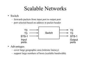
Scalable Networks
• Switch
–forwards packets from input port to output port
– port selected based on address in packet header
• Advantages
– cover large geographic area (tolerate latency)
– support large numbers of hosts (scalable bandwidth)
Input
ports
T3
T3
STS-1
T3
T3
STS-1
Switch
Output
ports
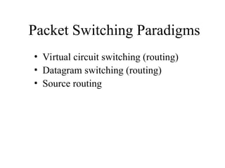
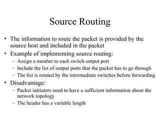
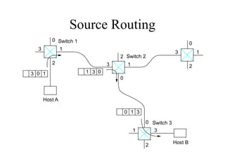
Source Routing
• Theinformation to route the packet is provided by the
source host and included in the packet
• Example of implementing source routing:
– Assign a number to each switch output port
– Include the list of output ports that the packet has to go through
– The list is rotated by the intermediate switches before forwarding
• Disadvantage:
– Packet initiators need to have a sufficient information about the
network topology
– The header has a variable length
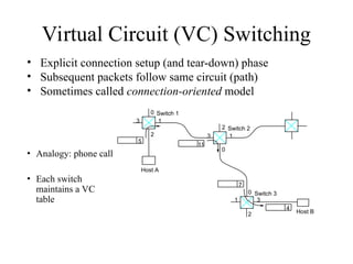
Virtual Circuit (VC)Switching
• Explicit connection setup (and tear-down) phase
• Subsequent packets follow same circuit (path)
• Sometimes called connection-oriented model
0
1
3
2
0
1 3
2
0
1
3
2
5
11
4
7
Switch 3
Host B
Switch 2
Host A
Switch 1
• Analogy: phone call
• Each switch
maintains a VC
table
8.
Virtual Circuit Switching
•Connection Setup approaches:
– Permanent Virtual Circuits (PVC): manually setup/removed by network
administrators
– Switched Virtual Circuits (SVC): dynamically setup through signaling
over some control channels
• Connection state => VC table
– incoming interface, VC Identifier (VCI), outgoing interface, outgoing VCI
• SVC:
– The setup message is forwarded over the network
– New entries are created in the VC table and destination switches choose
incoming VCI
– When the setup message reaches the destination, connection
acknowledgements and chosen VCI are communicated back to the source
9.
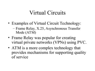
Virtual Circuits
• Examplesof Virtual Circuit Technology:
– Frame Relay, X.25, Asynchronous Transfer
Mode (ATM)
• Frame Relay was popular for creating
virtual private networks (VPNs) using PVC.
• ATM is a more complex technology that
provides mechanisms for supporting quality
of service
10.
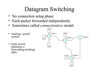
Datagram Switching
• Noconnection setup phase
• Each packet forwarded independently
• Sometimes called connectionless model
0
1
3
2
0
1 3
2
0
1
3
2
Switch 3
Switch 2
Host A
Switch 1
Host C
Host D
Host E
Host G
Host H
• Analogy: postal
system
• Each switch
maintains a
forwarding (routing)
table
Switch 4
11.
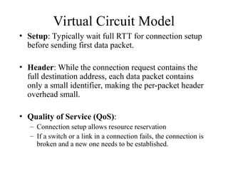
Virtual Circuit Model
•Setup: Typically wait full RTT for connection setup
before sending first data packet.
• Header: While the connection request contains the
full destination address, each data packet contains
only a small identifier, making the per-packet header
overhead small.
• Quality of Service (QoS):
– Connection setup allows resource reservation
– If a switch or a link in a connection fails, the connection is
broken and a new one needs to be established.
12.
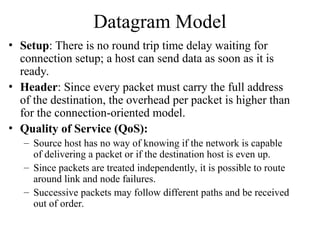
Datagram Model
• Setup:There is no round trip time delay waiting for
connection setup; a host can send data as soon as it is
ready.
• Header: Since every packet must carry the full address
of the destination, the overhead per packet is higher than
for the connection-oriented model.
• Quality of Service (QoS):
– Source host has no way of knowing if the network is capable
of delivering a packet or if the destination host is even up.
– Since packets are treated independently, it is possible to route
around link and node failures.
– Successive packets may follow different paths and be received
out of order.
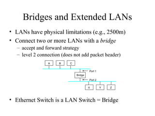
Bridges and ExtendedLANs
• LANs have physical limitations (e.g., 2500m)
• Connect two or more LANs with a bridge
– accept and forward strategy
– level 2 connection (does not add packet header)
• Ethernet Switch is a LAN Switch = Bridge
A
Bridge
B C
X Y Z
Port 1
Port 2
15.
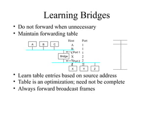
Learning Bridges
• Donot forward when unnecessary
• Maintain forwarding table
Host Port
A 1
B 1
C 1
X 2
Y 2
Z 2
• Learn table entries based on source address
• Table is an optimization; need not be complete
• Always forward broadcast frames
A
Bridge
B C
X Y Z
Port 1
Port 2
16.
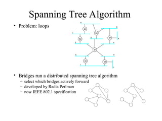
Spanning Tree Algorithm
•Problem: loops
• Bridges run a distributed spanning tree algorithm
– select which bridges actively forward
– developed by Radia Perlman
– now IEEE 802.1 specification
B3
A
C
E
D
B2
B5
B
B7 K
F
H
B4
J
B1
B6
G
I
17.
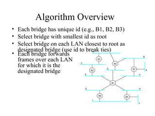
Algorithm Overview
• Eachbridge has unique id (e.g., B1, B2, B3)
• Select bridge with smallest id as root
• Select bridge on each LAN closest to root as
designated bridge (use id to break ties)
B3
A
C
E
D
B2
B5
B
B7 K
F
H
B4
J
B1
B6
G
I
• Each bridge forwards
frames over each LAN
for which it is the
designated bridge
18.
Algorithm Details
• Bridgesexchange configuration messages
– id for bridge sending the message
– id for what the sending bridge believes to be root
bridge
– distance (hops) from sending bridge to root bridge
• Each bridge records current best configuration
message for each port
• Initially, each bridge believes it is the root
19.
Algorithm Detail (cont)
•When learn not root, stop generating config messages
– in steady state, only root generates configuration messages
• When learn not designated bridge, stop forwarding
config messages
– in steady state, only designated bridges forward config
messages
• Root continues to periodically send config messages
• If any bridge does not receive config message after a
period of time, it starts generating config messages
claiming to be the root
20.
Broadcast and Multicast
•Forward all broadcast/multicast frames
– current practice
• Learn when no group members downstream
• Accomplished by having each member of
group G send a frame to bridge multicast
address with G in source field
21.
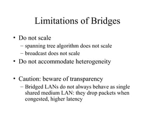
Limitations of Bridges
•Do not scale
– spanning tree algorithm does not scale
– broadcast does not scale
• Do not accommodate heterogeneity
• Caution: beware of transparency
– Bridged LANs do not always behave as single
shared medium LAN: they drop packets when
congested, higher latency
22.
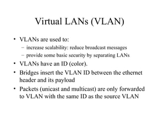
Virtual LANs (VLAN)
•VLANs are used to:
– increase scalability: reduce broadcast messages
– provide some basic security by separating LANs
• VLANs have an ID (color).
• Bridges insert the VLAN ID between the ethernet
header and its payload
• Packets (unicast and multicast) are only forwarded
to VLAN with the same ID as the source VLAN
Editor's Notes
#1 Review of Direct Link Networks. Should have seen them in COM3510.
Focus on results and practical considerations and not on how they were obtained.
#3 Limitation in number of input/output ports doesn’t mean that we cannot build large networks. Interconnection of switches allows to connect a large number of hosts.
Ethernet like networks do not scale to large distances. Switches can be connected by point-to-point links thus providing large geographic scope.
Adding new hosts doesn’t necessarily reduce the performance of other nodes.
#5 What techniques can be used to communicate between hosts in a switched network:
Source routing (could be used in some IP routing and in some cases in wireless ad hoc networks)
Virtual Circuit or connection-oriented approach.
Datagram approach or connectionless approach.
Instead of rotation, use a pointer
Used in the IP, loose source routing, wireless, connection setup
#8 Connection setup: to establish a connection state at intermediate switches
#9
Quality of service: throughput, congestion avoidance
#14 How do we extend bridges? Repeater, bridges, routers…
Scalability: 10Mbps + switches => ?
#21 One advantage of LANs is that you don’t have to run higher layer protocols: routing etc.


![Layanan Implementasi Simpatika[1] [Autosaved].pptx](https://cdn.slidesharecdn.com/ss_thumbnails/layananimplementasisimpatika1autosaved-240809034742-d65796a7-thumbnail.jpg?width=640&height=640&fit=bounds)


