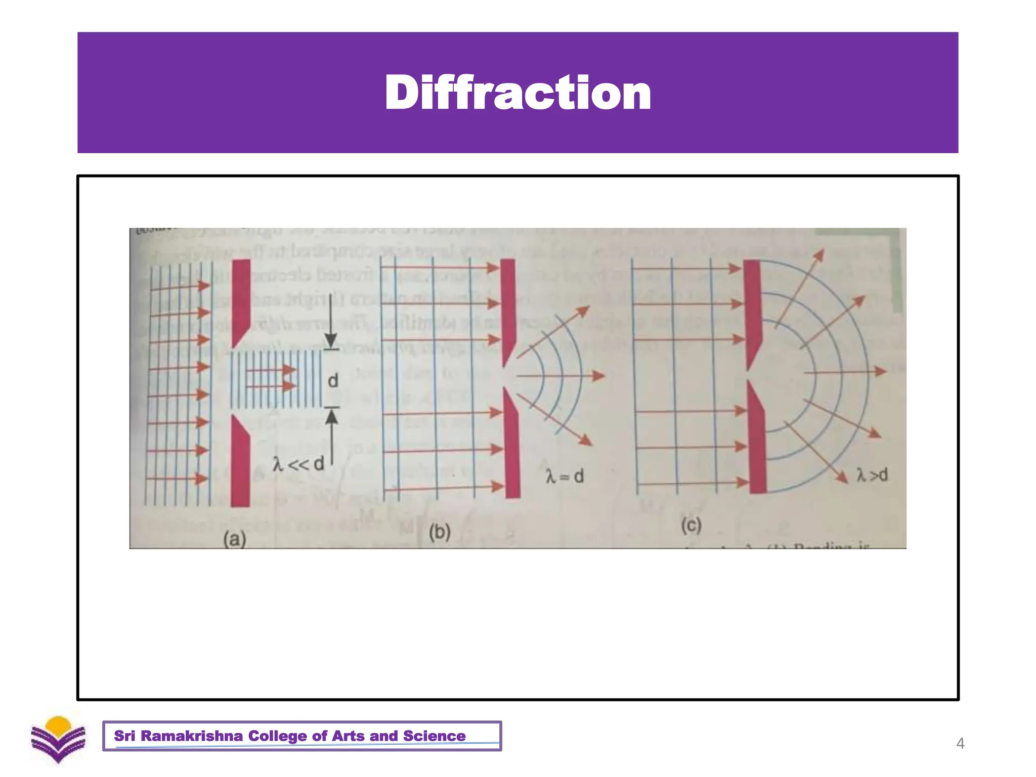
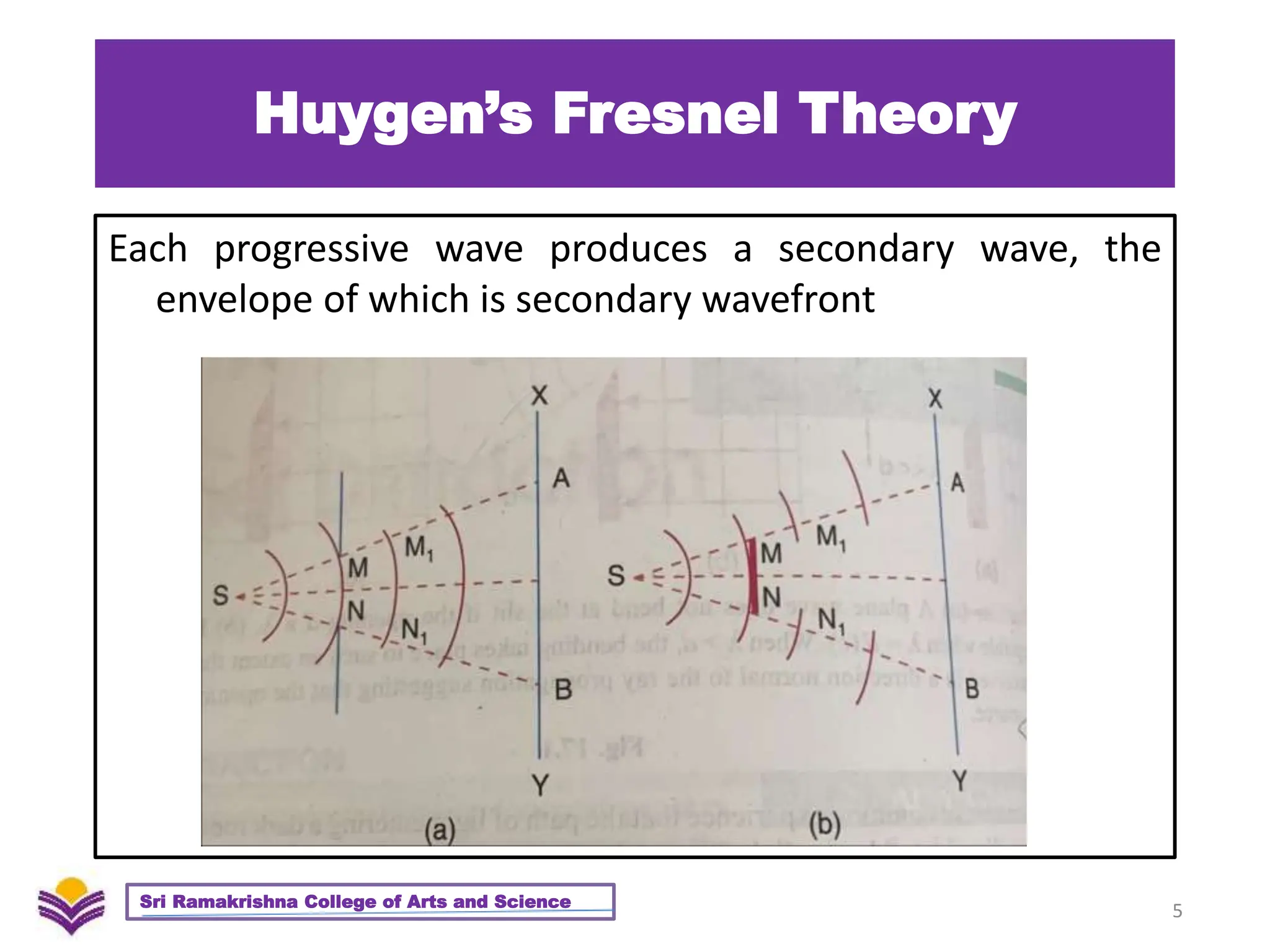
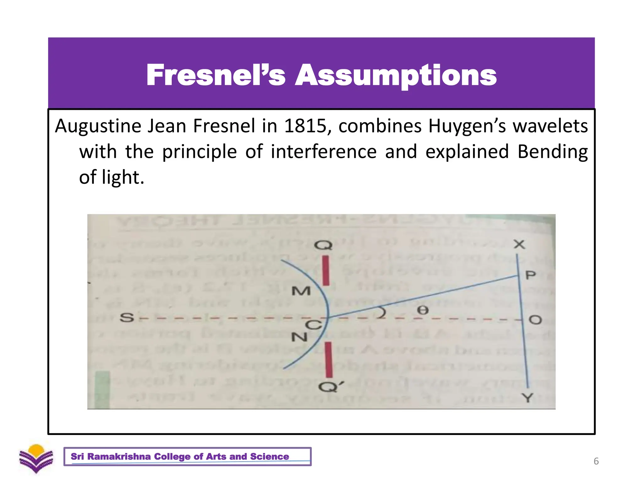
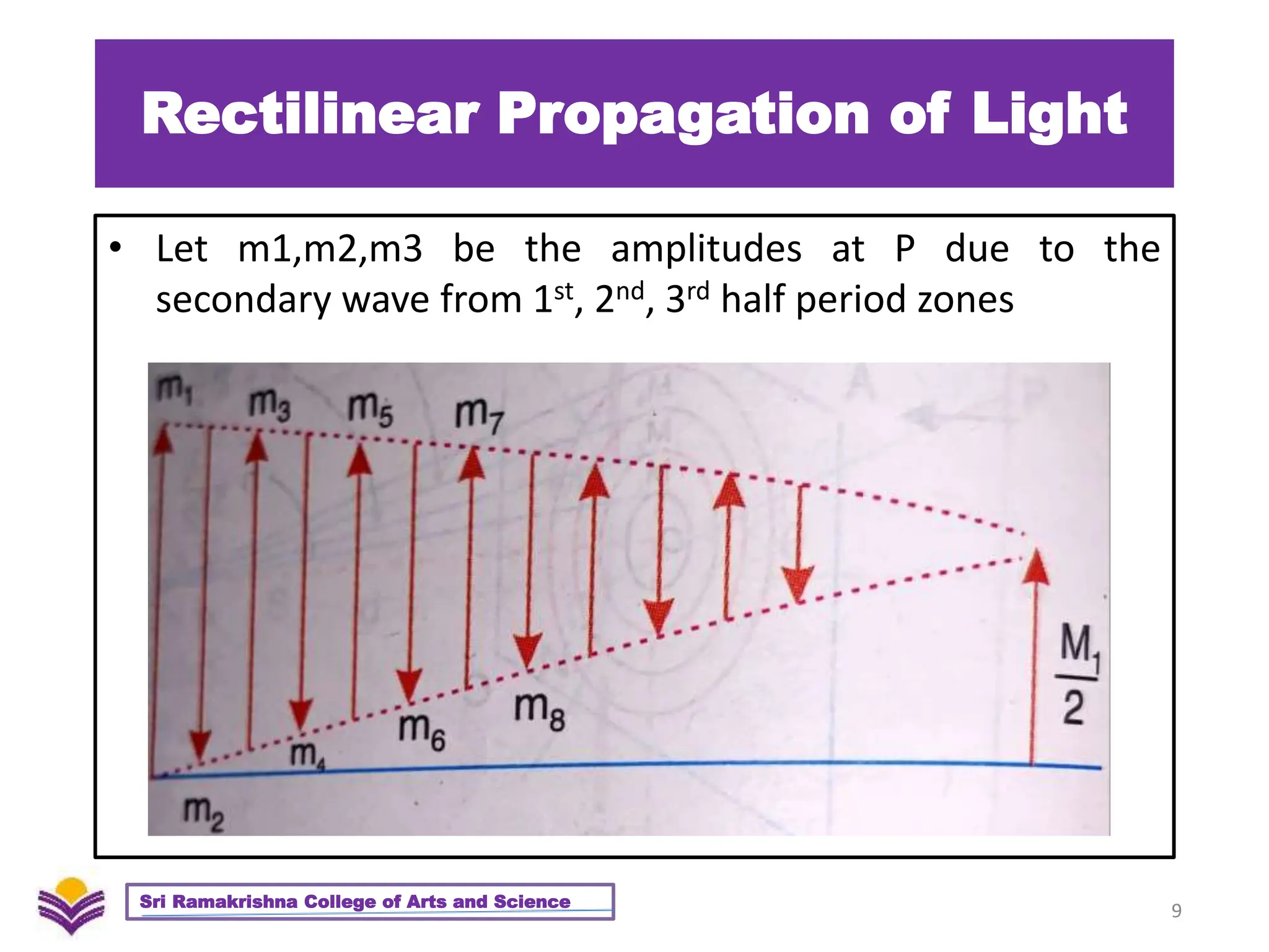
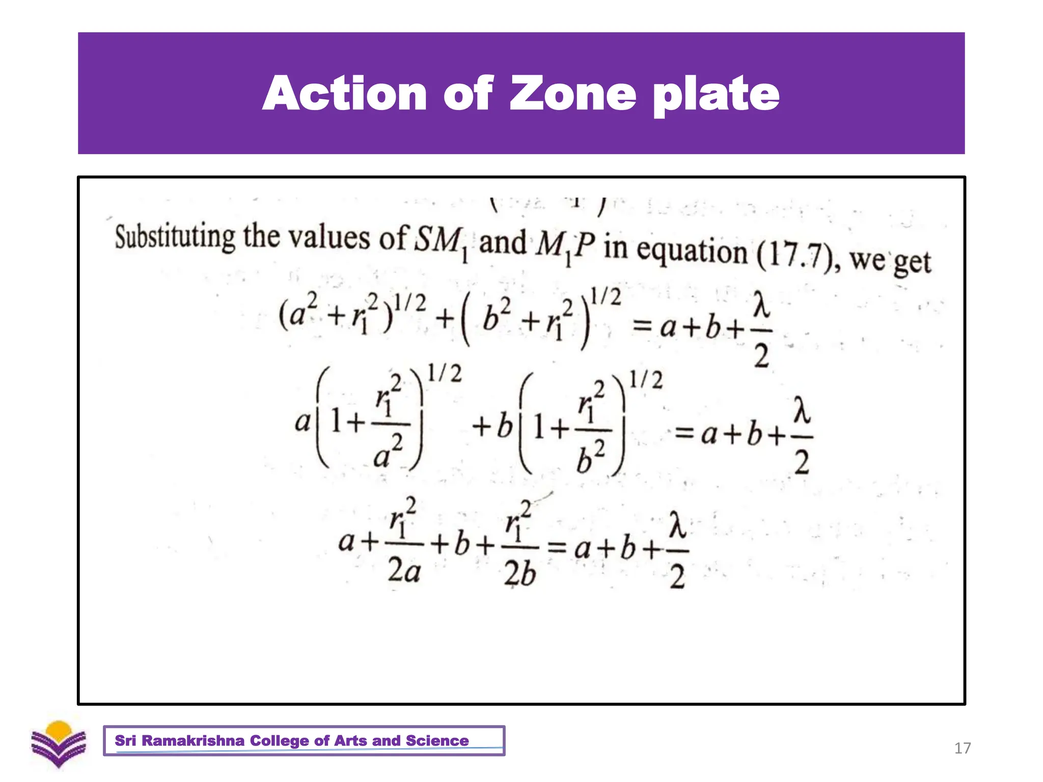
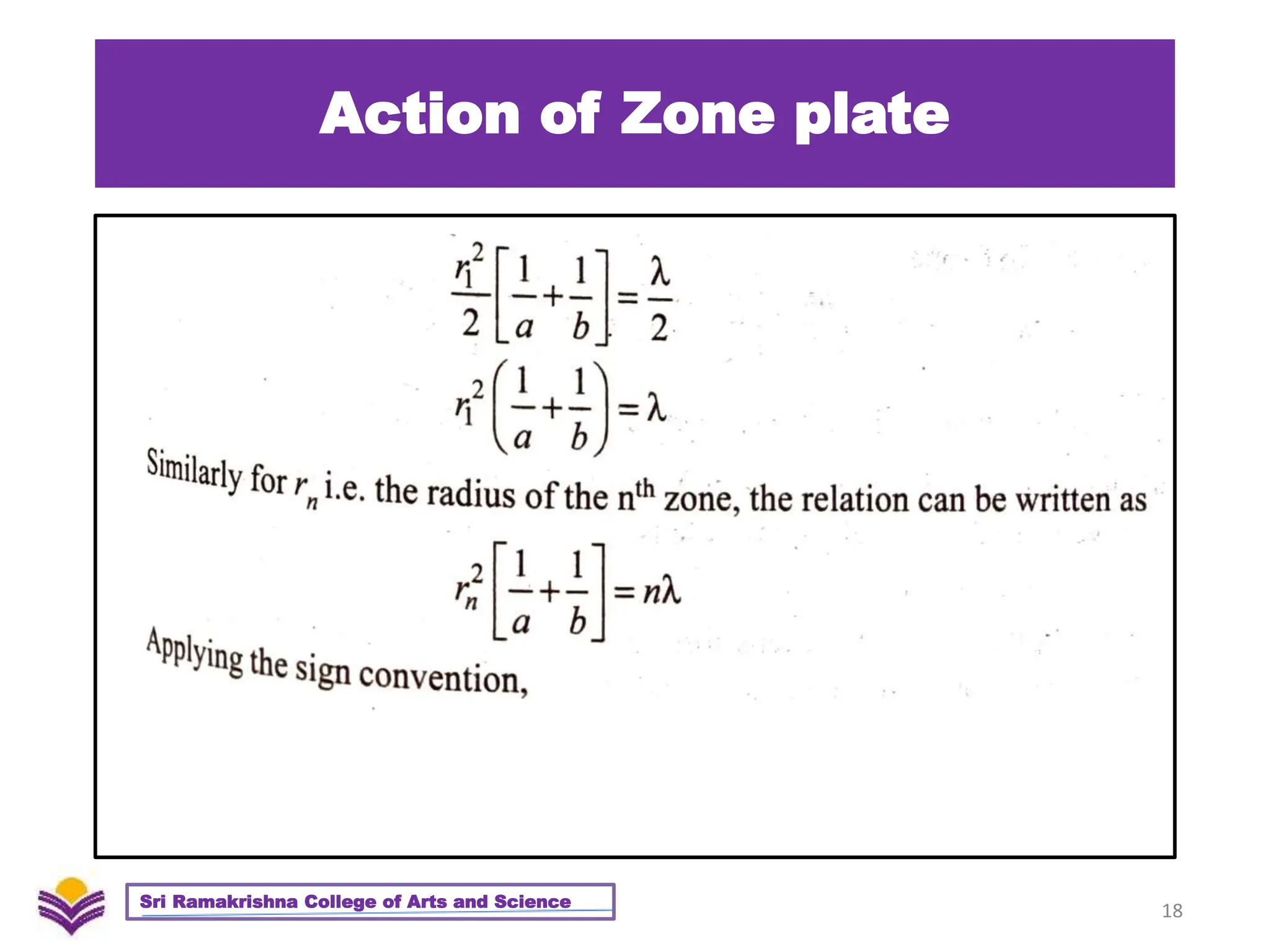
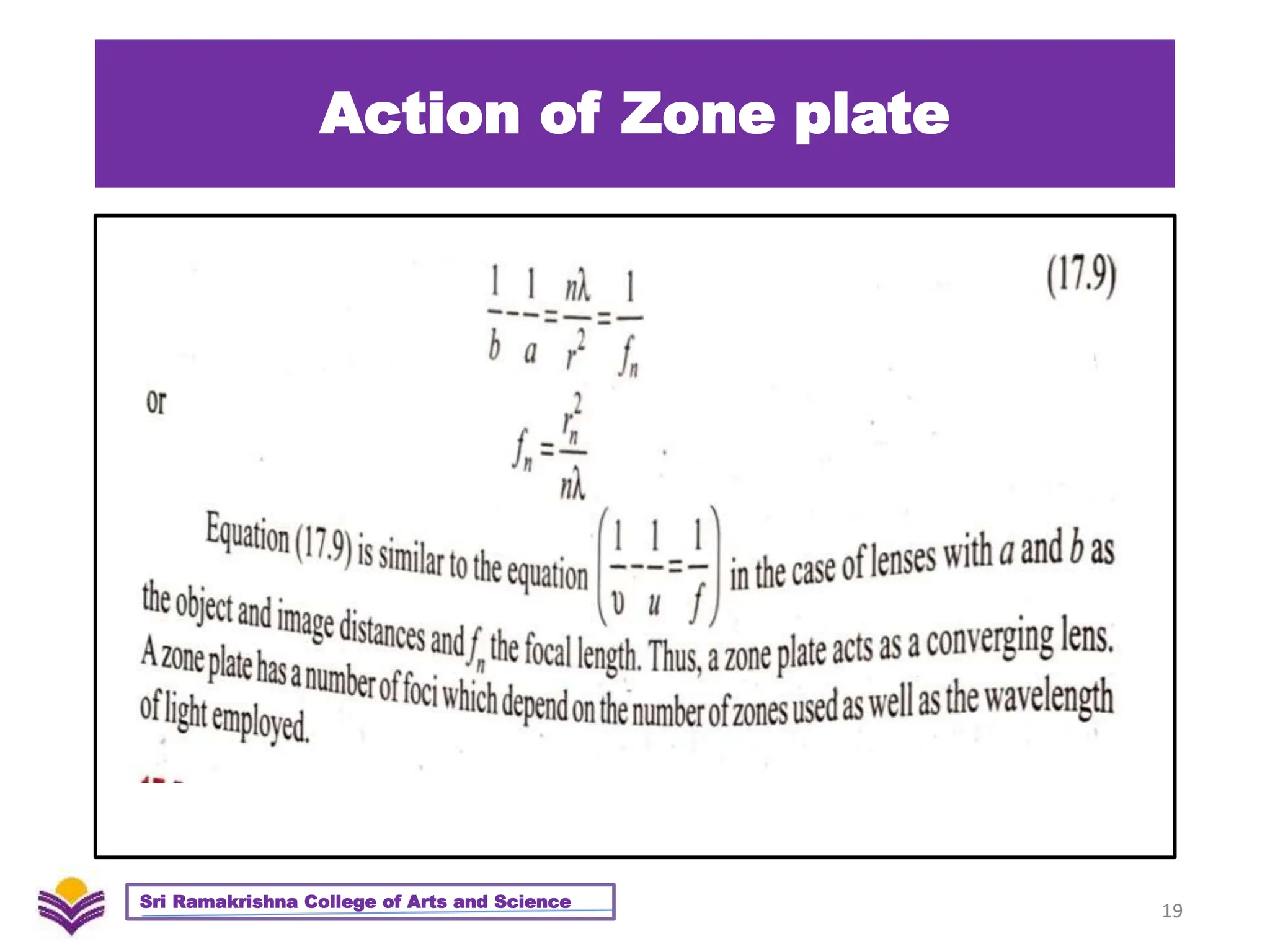
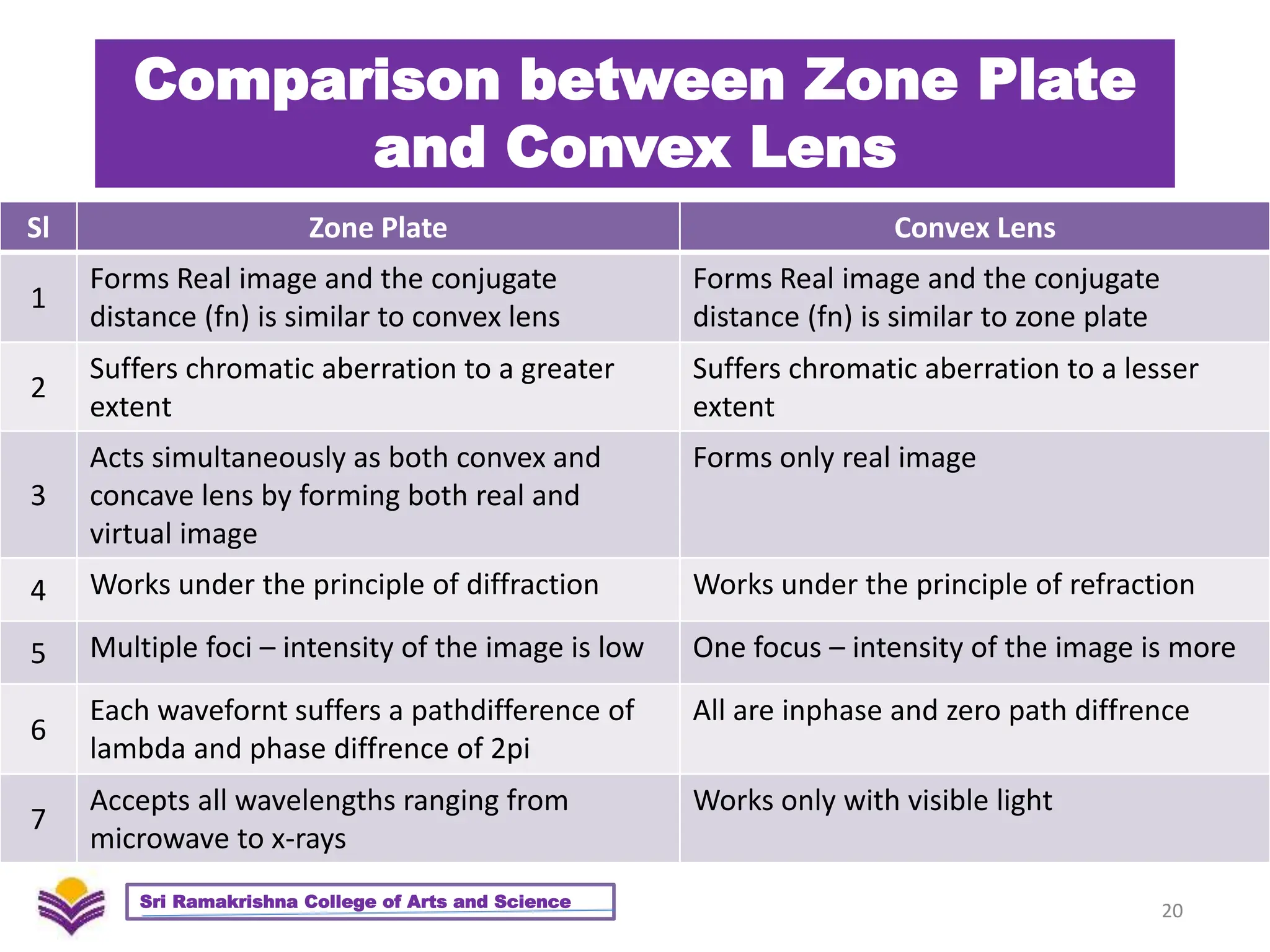
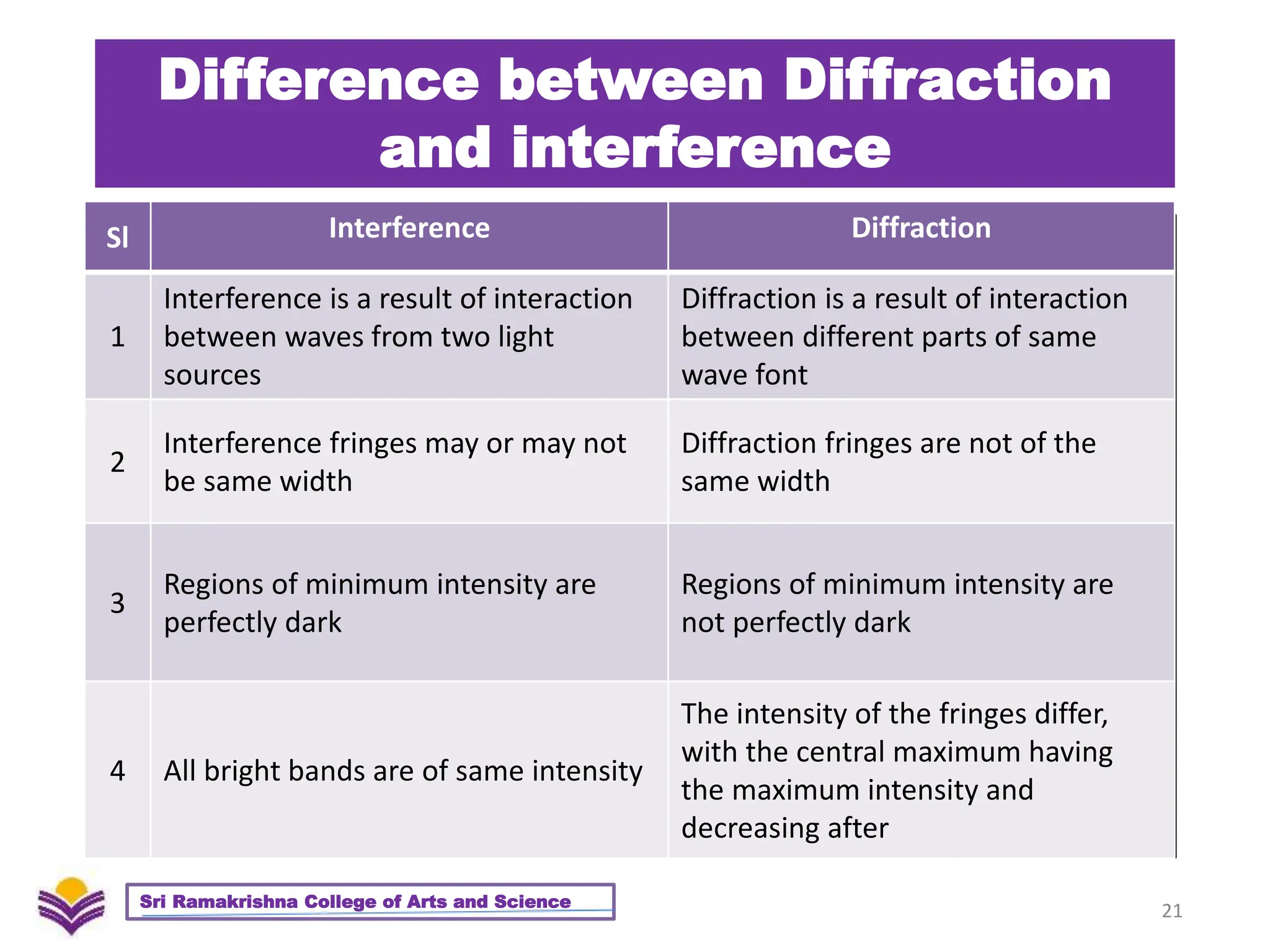
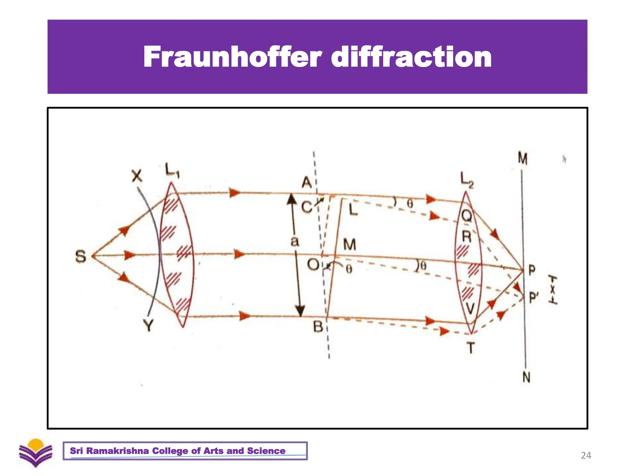
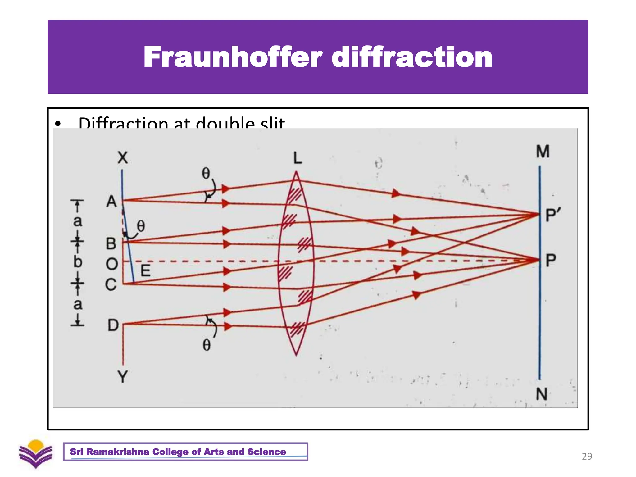
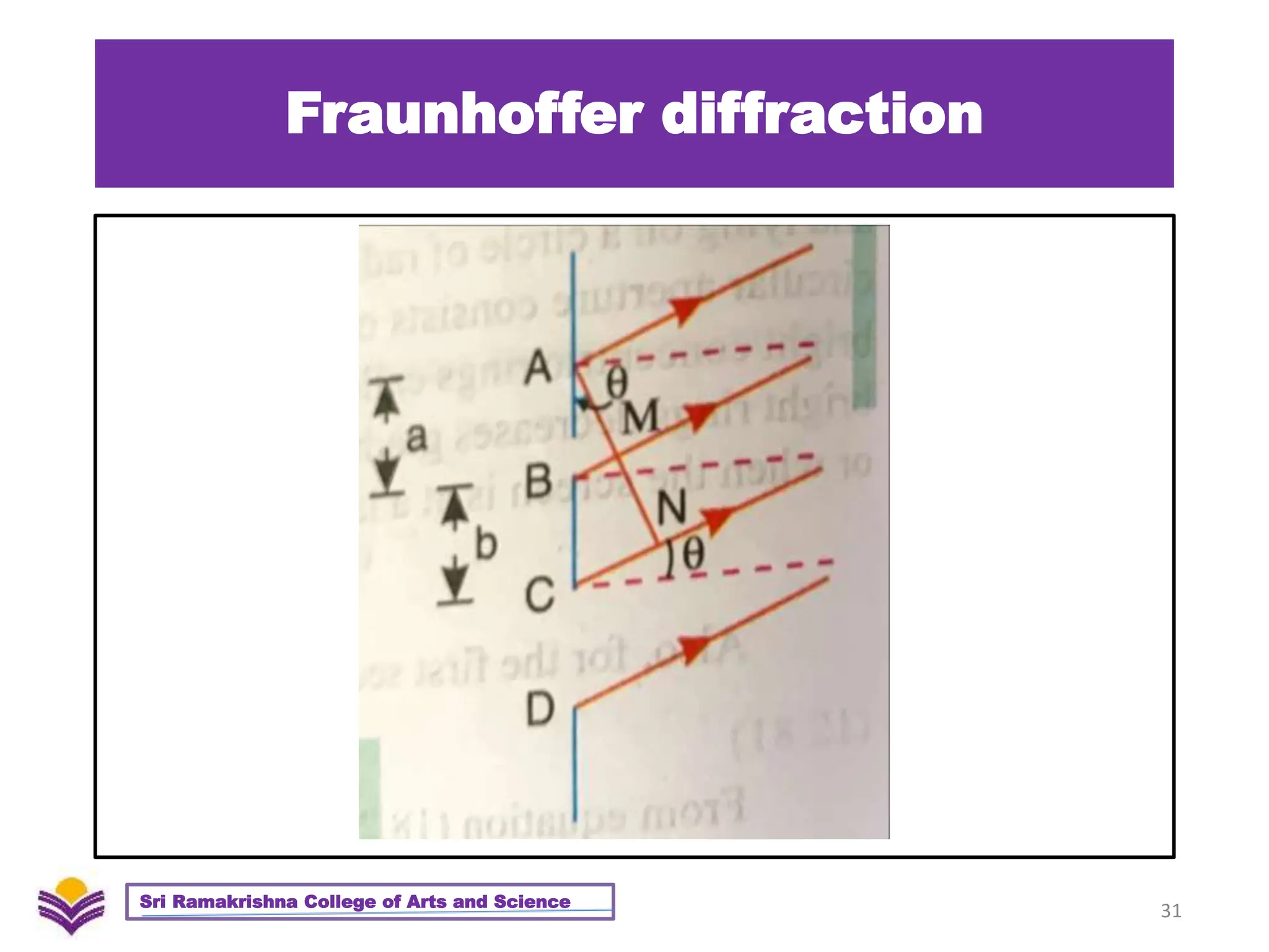
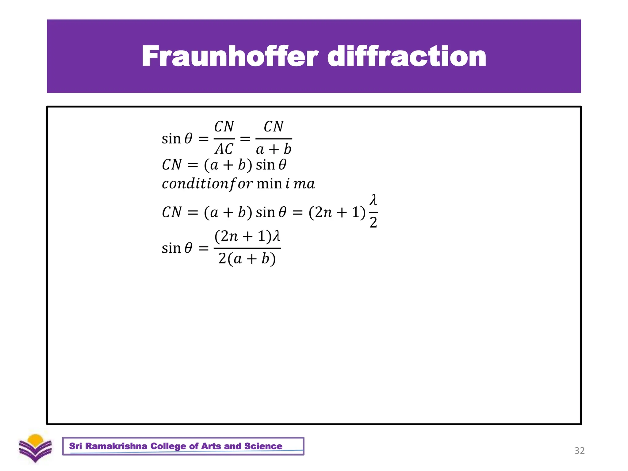
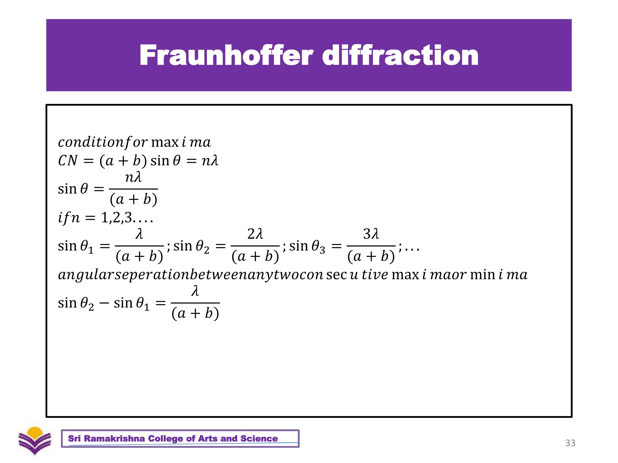
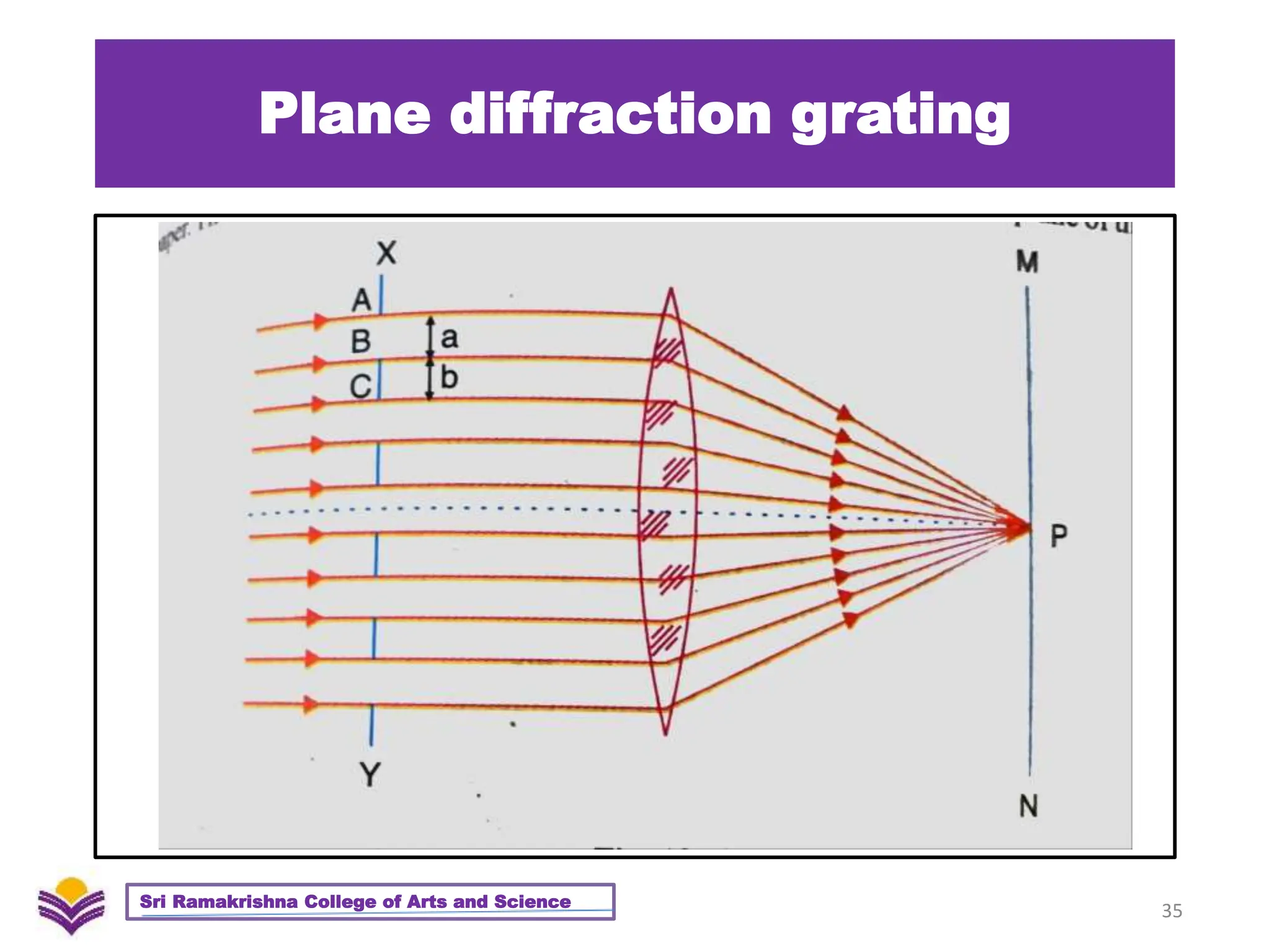
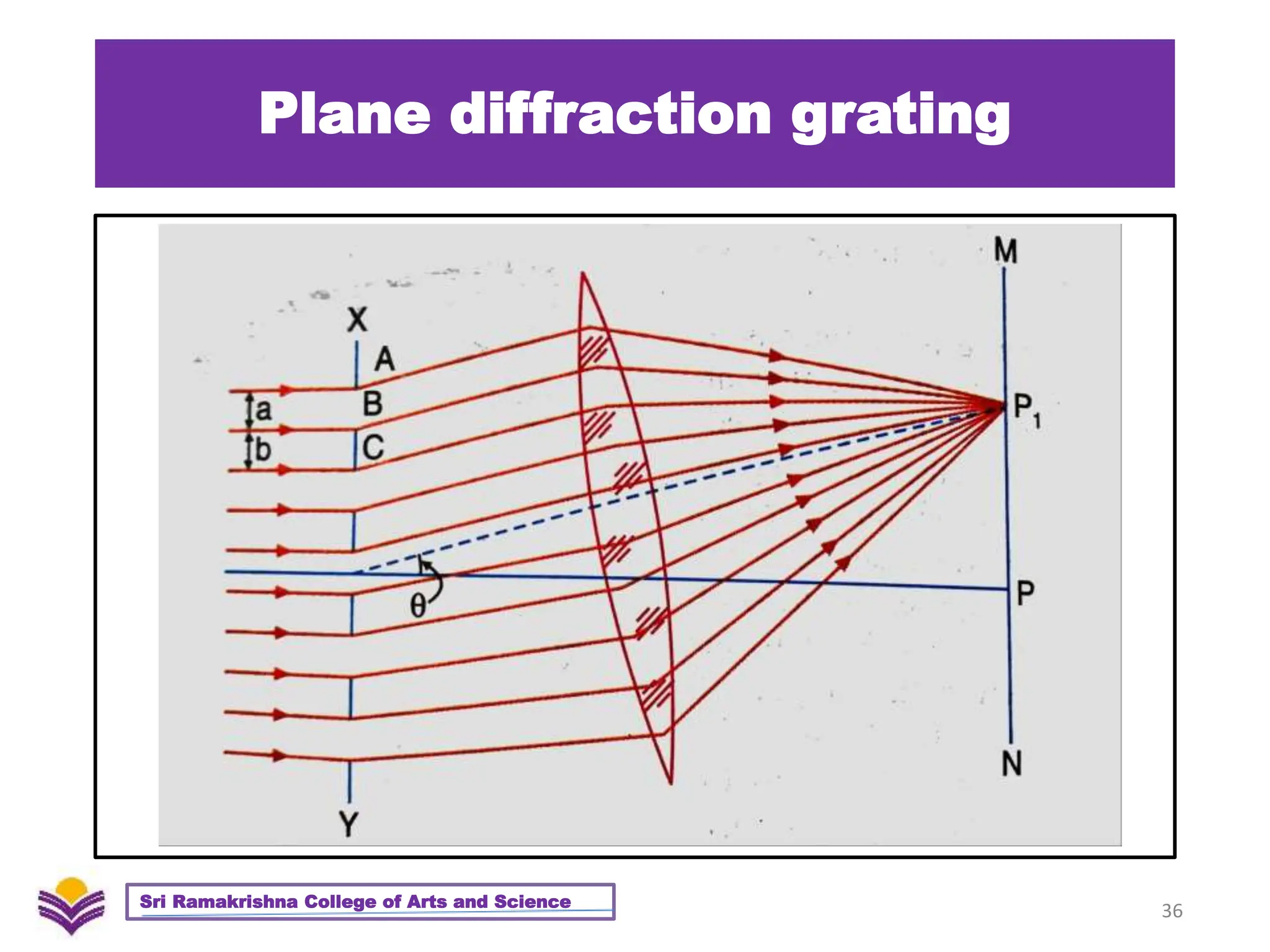
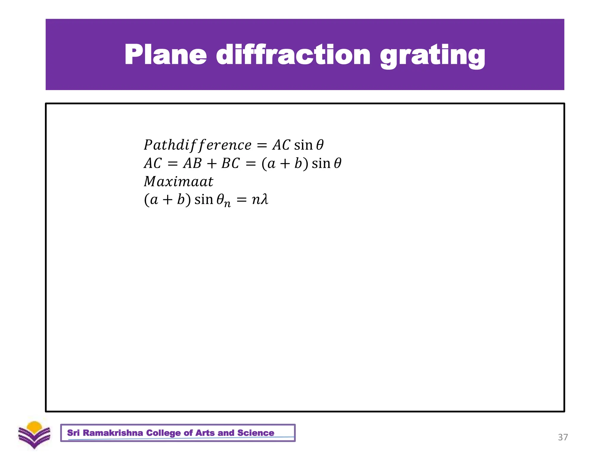
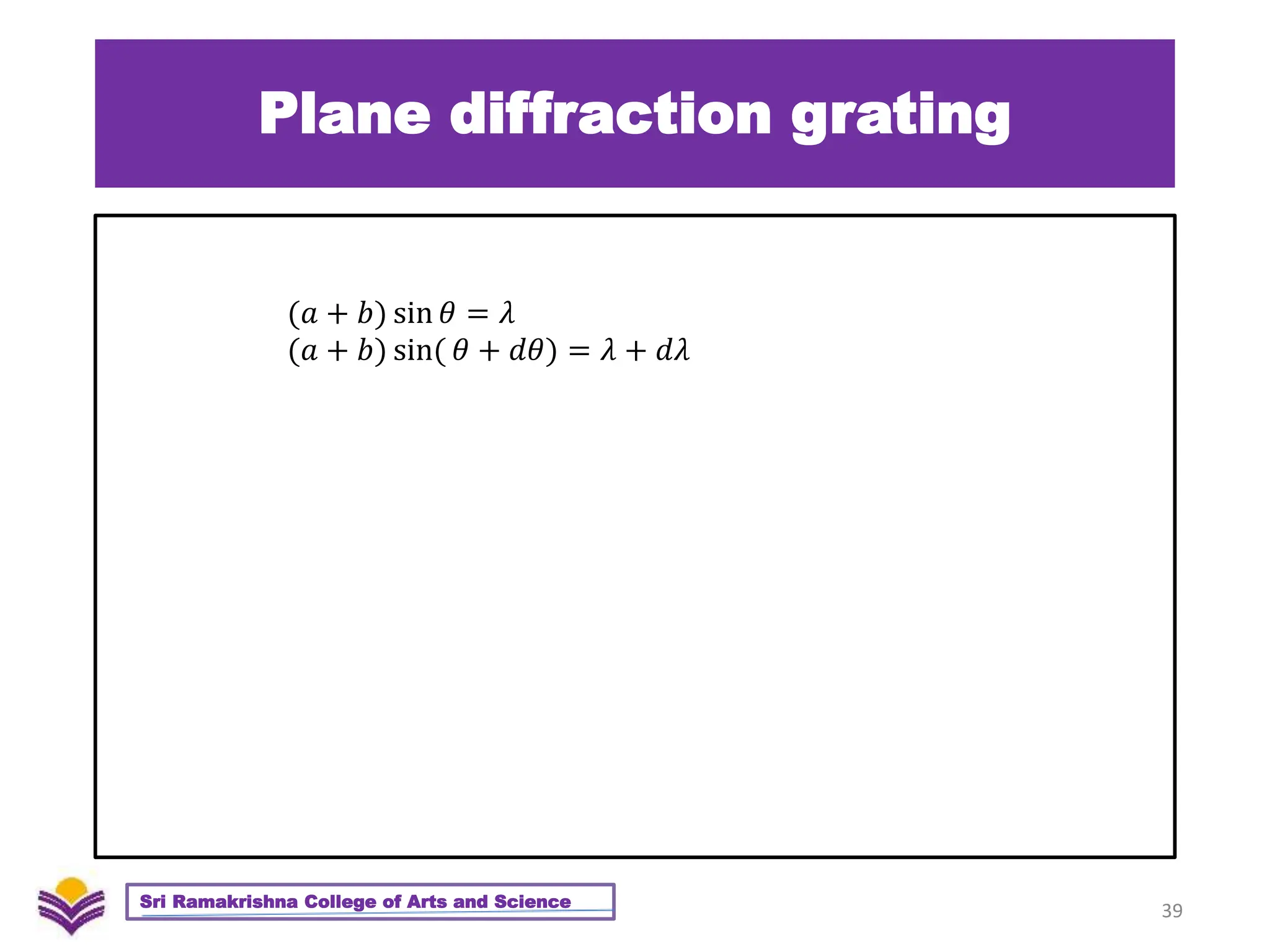
Optics
Ms Dhivya R
Assistant Professor
Department of Physics
Sri Ramakrishna College of Arts and Science
Coimbatore - 641 006
Tamil Nadu, India
1
U3 – Diffraction - Overview
1. Huygens – Fresnel Theory
2. Fresnel’s Assumptions
3. Rectilinear Propagation of light waves
4. Zone Plate
5. Action of Zone plate on a Spherical wavefront
6. Difference between Zone Plate and Convex Lens
7. Distinction between Interference and diffraction
8. Diffraction pattern due to straight edge
9. Diffraction pattern due to narrow slit
10. Fraunhofer diffraction
11. Fraunhofer Diffraction in single slit
12. Fraunhofer Diffraction in double slit
13. Plane Diffraction Grating
2
Sri Ramakrishna College of Arts and Science
Diffraction
• Diffraction refers to various phenomena that occur when a
wave encounters an obstacle or a slit.
• It is defined as the bending of waves around the corners
of an obstacle or through an aperture into the region of
geometrical shadow of the obstacle/aperture.
3
Sri Ramakrishna College of Arts and Science
Diffraction
4
Sri Ramakrishna College of Arts and Science
Huygen’s Fresnel Theory
Each progressive wave produces a secondary wave, the
envelope of which is secondary wavefront
5
Sri Ramakrishna College of Arts and Science
Fresnel’s Assumptions
Augustine Jean Fresnel in 1815, combines Huygen’s wavelets
with the principle of interference and explained Bending
of light.
6
Sri Ramakrishna College of Arts and Science
Fresnel’s Assumptions
1. A Wavefront can be divided into a large number of strips
called Zones (Fresnel’s Zones)
2. The affect at any particular point will depend on the
distance of the zone from the point
3. Effect will also depend on the obliquity of the point with
reference to the zone
7
Sri Ramakrishna College of Arts and Science
Rectilinear Propagation of Light
• Radii are proportional to the square root of the natural
numbers
ie
• The area of the zones are proportional to
• The wavelength of the light used
• The distance of the point from the wavefront (as discussed in
Fresnel’s assumptions)
8
Sri Ramakrishna College of Arts and Science
1𝑏𝜆, 2𝑏𝜆, 3𝑏𝜆, 4𝑏𝜆 𝑎𝑛𝑑 𝑠𝑜 𝑜𝑛
Rectilinear Propagation of Light
• Let m1,m2,m3 be the amplitudes at P due to the
secondary wave from 1st, 2nd, 3rd half period zones
9
Sri Ramakrishna College of Arts and Science
Rectilinear Propagation of Light
• As the amplitudes are of gradually decreasing magnitude,
the amplitude of vibration at P, due to any zone can be
approximately taken as the mean of the amplitudes due to
the zone preceding and succeeding it
10
Sri Ramakrishna College of Arts and Science
𝑒𝑔 𝑚2 =
𝑚1 + 𝑚3
2
𝑡ℎ𝑒 𝑟𝑒𝑠𝑢𝑙𝑡𝑎𝑛𝑡 𝑎𝑚𝑝𝑙𝑖𝑡𝑢𝑑𝑒 𝑎𝑡 𝑃 𝑎𝑡 𝑎𝑛𝑦 𝑖𝑛𝑠𝑡𝑎𝑛𝑡 𝑖𝑠 𝑔𝑖𝑣𝑒𝑛 𝑏𝑦
𝐴 = 𝑚1 − 𝑚2 + 𝑚3 − 𝑚4. . . . . . +𝑚𝑛𝑖𝑓𝑛 𝑖𝑠 𝑜𝑑𝑑.
𝑖𝑓 𝑛 𝑖𝑠 𝑒𝑣𝑒𝑛, 𝑡ℎ𝑒 𝑙𝑎𝑠𝑡 𝑞𝑢𝑎𝑛𝑡𝑖𝑡𝑦 𝑖𝑠 − 𝑚𝑛)
Rectilinear Propagation of Light
11
Sri Ramakrishna College of Arts and Science
𝐴 =
𝑚1
2
+
𝑚1
2
− 𝑚2 +
𝑚3
2
+
𝑚3
2
− 𝑚4 +
𝑚5
2
+. . . . . .
𝑏𝑢𝑡 𝑚2 =
𝑚1
2
+
𝑚3
2
𝑎𝑛𝑑 𝑚4 =
𝑚3
2
+
𝑚5
2
𝐴 =
𝑚1
2
+
𝑚𝑛
2
+. . . . . . (𝑖𝑓𝑛𝑖𝑠𝑜𝑑𝑑)
𝐴 =
𝑚1
2
+
𝑚𝑛−1
2
− 𝑚𝑛(𝑖𝑓𝑛𝑖𝑠𝑒𝑣𝑒𝑛)
Rectilinear Propagation of Light
12
Sri Ramakrishna College of Arts and Science
𝐴 =
𝑚1
2
𝑆𝑖𝑛𝑐𝑒 𝑡ℎ𝑒 𝑒𝑓𝑓𝑒𝑐𝑡 𝑑𝑢𝑒 𝑡𝑜 𝑡ℎ𝑒 𝑜𝑡ℎ𝑒𝑟 𝑧𝑜𝑛𝑒𝑠 𝑎𝑟𝑒 𝑑𝑒𝑐𝑟𝑒𝑎𝑠𝑖𝑛𝑔
𝐼𝛼
𝑚1
2
4
(∵ 𝐼 =
𝐴
2
)
Zone Plate
• Screen – Specially constructed to allow light from either
odd or even numbered zones alone
13
Sri Ramakrishna College of Arts and Science
Zone Plate
• If the source is at a larger distance from the zone plate, a
bright spot will be obtained at P
• If the even numbered zones are opaque
• 𝐴 = 𝑚1 + 𝑚3. . . . . . +𝑚𝑛 (brighter)
• 𝐴 = 𝑚1 − 𝑚2 + 𝑚3 − 𝑚4. . . . . . +𝑚𝑛 for unobstructed
• Whitelight source – different colours come to focus at diff
points along OP. ZP Similar to Convex Lens.
14
Sri Ramakrishna College of Arts and Science
𝑟1 = 𝑏𝜆 𝑟2 = 2𝑏𝜆 𝑟𝑛 = 𝑛𝑏𝜆
𝑏 =
𝑟𝑛
2
𝑛𝜆
𝑏 = 𝑓𝑛 =
𝑟𝑛
2
𝑛𝜆
Action of Zone plate
15
Sri Ramakrishna College of Arts and Science
Action of Zone plate
16
Sri Ramakrishna College of Arts and Science
Action of Zone plate
17
Sri Ramakrishna College of Arts and Science
Action of Zone plate
18
Sri Ramakrishna College of Arts and Science
Action of Zone plate
19
Sri Ramakrishna College of Arts and Science
Comparison between Zone Plate
and Convex Lens
20
Sri Ramakrishna College of Arts and Science
Sl Zone Plate Convex Lens
1
Forms Real image and the conjugate
distance (fn) is similar to convex lens
Forms Real image and the conjugate
distance (fn) is similar to zone plate
2
Suffers chromatic aberration to a greater
extent
Suffers chromatic aberration to a lesser
extent
3
Acts simultaneously as both convex and
concave lens by forming both real and
virtual image
Forms only real image
4 Works under the principle of diffraction Works under the principle of refraction
5 Multiple foci – intensity of the image is low One focus – intensity of the image is more
6
Each wavefornt suffers a pathdifference of
lambda and phase diffrence of 2pi
All are inphase and zero path diffrence
7
Accepts all wavelengths ranging from
microwave to x-rays
Works only with visible light
Difference between Diffraction
and interference
21
Sri Ramakrishna College of Arts and Science
Sl Interference Diffraction
1
Interference is a result of interaction
between waves from two light
sources
Diffraction is a result of interaction
between different parts of same
wave font
2
Interference fringes may or may not
be same width
Diffraction fringes are not of the
same width
3
Regions of minimum intensity are
perfectly dark
Regions of minimum intensity are
not perfectly dark
4 All bright bands are of same intensity
The intensity of the fringes differ,
with the central maximum having
the maximum intensity and
decreasing after
Fresnel diffraction
• Source at a finite distance from the slit
• Diffraction pattern collected on screen without the help of
lens
22
Sri Ramakrishna College of Arts and Science
Fraunhoffer diffraction
• Incident wave front must be plane
• Diffraction pattern collected on screen with the help of
lens
• Source must be at infinity from the slit
23
Sri Ramakrishna College of Arts and Science
Fraunhoffer diffraction
24
Sri Ramakrishna College of Arts and Science
Fraunhoffer diffraction
25
Sri Ramakrishna College of Arts and Science
sin 𝜃 =
𝐴𝐿
𝐴𝐵
=
𝐴𝐿
𝑎
𝐴𝐿 = 𝑎 sin 𝜃
𝑎 sin 𝜃𝑛 = 𝑛𝜆
Fraunhoffer diffraction
26
Sri Ramakrishna College of Arts and Science
𝑎 sin 𝜃𝑛 = (2𝑛 + 1)
𝜆
2
𝑎 sin 𝜃𝑛 =
(2𝑛 + 1)𝜆
2𝑎
Fraunhoffer diffraction
27
Sri Ramakrishna College of Arts and Science
sin 𝜃 =
𝑥
𝑓
𝑏𝑢𝑡 sin 𝜃 =
𝜆
𝑎
ℎ𝑒𝑛𝑐𝑒
𝑥
𝑓
=
𝜆
𝑎
𝑜𝑟𝑥 =
𝑓𝜆
𝑎
𝑊𝑖𝑑𝑡ℎ = 2𝑥 =
2𝑓𝜆
𝑎
Fraunhoffer diffraction
28
Sri Ramakrishna College of Arts and Science
Fraunhoffer diffraction
• Diffraction at double slit
29
Sri Ramakrishna College of Arts and Science
Fraunhoffer diffraction
• Diffraction phenomenon due to two things
• Interference due to secondary waves from the corresponding
points at the two slits
• Diffraction due to the secondary waves from the two slits
individually
• Diffraction angle is denoted as Ѳ (angle between direction of
direct ray and the direction of secondary waves)
30
Sri Ramakrishna College of Arts and Science
Fraunhoffer diffraction
31
Sri Ramakrishna College of Arts and Science
Fraunhoffer diffraction
32
Sri Ramakrishna College of Arts and Science
sin 𝜃 =
𝐶𝑁
𝐴𝐶
=
𝐶𝑁
𝑎 + 𝑏
𝐶𝑁 = (𝑎 + 𝑏) sin 𝜃
𝑐𝑜𝑛𝑑𝑖𝑡𝑖𝑜𝑛𝑓𝑜𝑟 min 𝑖 𝑚𝑎
𝐶𝑁 = (𝑎 + 𝑏) sin 𝜃 = (2𝑛 + 1)
𝜆
2
sin 𝜃 =
(2𝑛 + 1)𝜆
2(𝑎 + 𝑏)
Fraunhoffer diffraction
33
Sri Ramakrishna College of Arts and Science
𝑐𝑜𝑛𝑑𝑖𝑡𝑖𝑜𝑛𝑓𝑜𝑟 max 𝑖 𝑚𝑎
𝐶𝑁 = (𝑎 + 𝑏) sin 𝜃 = 𝑛𝜆
sin 𝜃 =
𝑛𝜆
(𝑎 + 𝑏)
𝑖𝑓𝑛 = 1,2,3. . . .
sin 𝜃1 =
𝜆
(𝑎 + 𝑏)
; sin 𝜃2 =
2𝜆
(𝑎 + 𝑏)
; sin 𝜃3 =
3𝜆
(𝑎 + 𝑏)
; . . .
𝑎𝑛𝑔𝑢𝑙𝑎𝑟𝑠𝑒𝑝𝑒𝑟𝑎𝑡𝑖𝑜𝑛𝑏𝑒𝑡𝑤𝑒𝑒𝑛𝑎𝑛𝑦𝑡𝑤𝑜𝑐𝑜𝑛 sec 𝑢 𝑡𝑖𝑣𝑒 max 𝑖 𝑚𝑎𝑜𝑟 min 𝑖 𝑚𝑎
sin 𝜃2 − sin 𝜃1 =
𝜆
(𝑎 + 𝑏)
Plane diffraction grating
• Large number of narrow slits side by side
• Slits separated by opaque spaces
• Light transmitted through slit and blocked by opaque
regions
• So they are called Plane Transmission Grating
34
Sri Ramakrishna College of Arts and Science
Plane diffraction grating
35
Sri Ramakrishna College of Arts and Science
Plane diffraction grating
36
Sri Ramakrishna College of Arts and Science
Plane diffraction grating
37
Sri Ramakrishna College of Arts and Science
𝑃𝑎𝑡ℎ𝑑𝑖𝑓𝑓𝑒𝑟𝑒𝑛𝑐𝑒 = 𝐴𝐶 sin 𝜃
𝐴𝐶 = 𝐴𝐵 + 𝐵𝐶 = (𝑎 + 𝑏) sin 𝜃
𝑀𝑎𝑥𝑖𝑚𝑎𝑎𝑡
(𝑎 + 𝑏) sin 𝜃𝑛 = 𝑛𝜆
Plane diffraction grating
• Number of Principal maxima = Number of wavelengths
• Angle of different wavelengths are different
• if there are two wavelengths
38
Sri Ramakrishna College of Arts and Science
𝜆𝑎𝑛𝑑𝑑𝜆𝑠𝑜𝑡ℎ𝑒𝑑𝑖𝑓𝑓𝑟𝑒𝑐𝑡𝑖𝑜𝑛𝑎𝑛𝑔𝑙𝑒𝑠𝑎𝑟𝑒
𝜃𝑎𝑛𝑑𝑑𝜃
Plane diffraction grating
39
Sri Ramakrishna College of Arts and Science
(𝑎 + 𝑏) sin 𝜃 = 𝜆
(𝑎 + 𝑏) sin( 𝜃 + 𝑑𝜃) = 𝜆 + 𝑑𝜆

23PH301 - Optics - Unit 3 - Diffraction.pptx

  • 1.
    Optics Ms Dhivya R AssistantProfessor Department of Physics Sri Ramakrishna College of Arts and Science Coimbatore - 641 006 Tamil Nadu, India 1
  • 2.
    U3 – Diffraction- Overview 1. Huygens – Fresnel Theory 2. Fresnel’s Assumptions 3. Rectilinear Propagation of light waves 4. Zone Plate 5. Action of Zone plate on a Spherical wavefront 6. Difference between Zone Plate and Convex Lens 7. Distinction between Interference and diffraction 8. Diffraction pattern due to straight edge 9. Diffraction pattern due to narrow slit 10. Fraunhofer diffraction 11. Fraunhofer Diffraction in single slit 12. Fraunhofer Diffraction in double slit 13. Plane Diffraction Grating 2 Sri Ramakrishna College of Arts and Science
  • 3.
    Diffraction • Diffraction refersto various phenomena that occur when a wave encounters an obstacle or a slit. • It is defined as the bending of waves around the corners of an obstacle or through an aperture into the region of geometrical shadow of the obstacle/aperture. 3 Sri Ramakrishna College of Arts and Science
  • 4.
  • 5.
    Huygen’s Fresnel Theory Eachprogressive wave produces a secondary wave, the envelope of which is secondary wavefront 5 Sri Ramakrishna College of Arts and Science
  • 6.
    Fresnel’s Assumptions Augustine JeanFresnel in 1815, combines Huygen’s wavelets with the principle of interference and explained Bending of light. 6 Sri Ramakrishna College of Arts and Science
  • 7.
    Fresnel’s Assumptions 1. AWavefront can be divided into a large number of strips called Zones (Fresnel’s Zones) 2. The affect at any particular point will depend on the distance of the zone from the point 3. Effect will also depend on the obliquity of the point with reference to the zone 7 Sri Ramakrishna College of Arts and Science
  • 8.
    Rectilinear Propagation ofLight • Radii are proportional to the square root of the natural numbers ie • The area of the zones are proportional to • The wavelength of the light used • The distance of the point from the wavefront (as discussed in Fresnel’s assumptions) 8 Sri Ramakrishna College of Arts and Science 1𝑏𝜆, 2𝑏𝜆, 3𝑏𝜆, 4𝑏𝜆 𝑎𝑛𝑑 𝑠𝑜 𝑜𝑛
  • 9.
    Rectilinear Propagation ofLight • Let m1,m2,m3 be the amplitudes at P due to the secondary wave from 1st, 2nd, 3rd half period zones 9 Sri Ramakrishna College of Arts and Science
  • 10.
    Rectilinear Propagation ofLight • As the amplitudes are of gradually decreasing magnitude, the amplitude of vibration at P, due to any zone can be approximately taken as the mean of the amplitudes due to the zone preceding and succeeding it 10 Sri Ramakrishna College of Arts and Science 𝑒𝑔 𝑚2 = 𝑚1 + 𝑚3 2 𝑡ℎ𝑒 𝑟𝑒𝑠𝑢𝑙𝑡𝑎𝑛𝑡 𝑎𝑚𝑝𝑙𝑖𝑡𝑢𝑑𝑒 𝑎𝑡 𝑃 𝑎𝑡 𝑎𝑛𝑦 𝑖𝑛𝑠𝑡𝑎𝑛𝑡 𝑖𝑠 𝑔𝑖𝑣𝑒𝑛 𝑏𝑦 𝐴 = 𝑚1 − 𝑚2 + 𝑚3 − 𝑚4. . . . . . +𝑚𝑛𝑖𝑓𝑛 𝑖𝑠 𝑜𝑑𝑑. 𝑖𝑓 𝑛 𝑖𝑠 𝑒𝑣𝑒𝑛, 𝑡ℎ𝑒 𝑙𝑎𝑠𝑡 𝑞𝑢𝑎𝑛𝑡𝑖𝑡𝑦 𝑖𝑠 − 𝑚𝑛)
  • 11.
    Rectilinear Propagation ofLight 11 Sri Ramakrishna College of Arts and Science 𝐴 = 𝑚1 2 + 𝑚1 2 − 𝑚2 + 𝑚3 2 + 𝑚3 2 − 𝑚4 + 𝑚5 2 +. . . . . . 𝑏𝑢𝑡 𝑚2 = 𝑚1 2 + 𝑚3 2 𝑎𝑛𝑑 𝑚4 = 𝑚3 2 + 𝑚5 2 𝐴 = 𝑚1 2 + 𝑚𝑛 2 +. . . . . . (𝑖𝑓𝑛𝑖𝑠𝑜𝑑𝑑) 𝐴 = 𝑚1 2 + 𝑚𝑛−1 2 − 𝑚𝑛(𝑖𝑓𝑛𝑖𝑠𝑒𝑣𝑒𝑛)
  • 12.
    Rectilinear Propagation ofLight 12 Sri Ramakrishna College of Arts and Science 𝐴 = 𝑚1 2 𝑆𝑖𝑛𝑐𝑒 𝑡ℎ𝑒 𝑒𝑓𝑓𝑒𝑐𝑡 𝑑𝑢𝑒 𝑡𝑜 𝑡ℎ𝑒 𝑜𝑡ℎ𝑒𝑟 𝑧𝑜𝑛𝑒𝑠 𝑎𝑟𝑒 𝑑𝑒𝑐𝑟𝑒𝑎𝑠𝑖𝑛𝑔 𝐼𝛼 𝑚1 2 4 (∵ 𝐼 = 𝐴 2 )
  • 13.
    Zone Plate • Screen– Specially constructed to allow light from either odd or even numbered zones alone 13 Sri Ramakrishna College of Arts and Science
  • 14.
    Zone Plate • Ifthe source is at a larger distance from the zone plate, a bright spot will be obtained at P • If the even numbered zones are opaque • 𝐴 = 𝑚1 + 𝑚3. . . . . . +𝑚𝑛 (brighter) • 𝐴 = 𝑚1 − 𝑚2 + 𝑚3 − 𝑚4. . . . . . +𝑚𝑛 for unobstructed • Whitelight source – different colours come to focus at diff points along OP. ZP Similar to Convex Lens. 14 Sri Ramakrishna College of Arts and Science 𝑟1 = 𝑏𝜆 𝑟2 = 2𝑏𝜆 𝑟𝑛 = 𝑛𝑏𝜆 𝑏 = 𝑟𝑛 2 𝑛𝜆 𝑏 = 𝑓𝑛 = 𝑟𝑛 2 𝑛𝜆
  • 15.
    Action of Zoneplate 15 Sri Ramakrishna College of Arts and Science
  • 16.
    Action of Zoneplate 16 Sri Ramakrishna College of Arts and Science
  • 17.
    Action of Zoneplate 17 Sri Ramakrishna College of Arts and Science
  • 18.
    Action of Zoneplate 18 Sri Ramakrishna College of Arts and Science
  • 19.
    Action of Zoneplate 19 Sri Ramakrishna College of Arts and Science
  • 20.
    Comparison between ZonePlate and Convex Lens 20 Sri Ramakrishna College of Arts and Science Sl Zone Plate Convex Lens 1 Forms Real image and the conjugate distance (fn) is similar to convex lens Forms Real image and the conjugate distance (fn) is similar to zone plate 2 Suffers chromatic aberration to a greater extent Suffers chromatic aberration to a lesser extent 3 Acts simultaneously as both convex and concave lens by forming both real and virtual image Forms only real image 4 Works under the principle of diffraction Works under the principle of refraction 5 Multiple foci – intensity of the image is low One focus – intensity of the image is more 6 Each wavefornt suffers a pathdifference of lambda and phase diffrence of 2pi All are inphase and zero path diffrence 7 Accepts all wavelengths ranging from microwave to x-rays Works only with visible light
  • 21.
    Difference between Diffraction andinterference 21 Sri Ramakrishna College of Arts and Science Sl Interference Diffraction 1 Interference is a result of interaction between waves from two light sources Diffraction is a result of interaction between different parts of same wave font 2 Interference fringes may or may not be same width Diffraction fringes are not of the same width 3 Regions of minimum intensity are perfectly dark Regions of minimum intensity are not perfectly dark 4 All bright bands are of same intensity The intensity of the fringes differ, with the central maximum having the maximum intensity and decreasing after
  • 22.
    Fresnel diffraction • Sourceat a finite distance from the slit • Diffraction pattern collected on screen without the help of lens 22 Sri Ramakrishna College of Arts and Science
  • 23.
    Fraunhoffer diffraction • Incidentwave front must be plane • Diffraction pattern collected on screen with the help of lens • Source must be at infinity from the slit 23 Sri Ramakrishna College of Arts and Science
  • 24.
    Fraunhoffer diffraction 24 Sri RamakrishnaCollege of Arts and Science
  • 25.
    Fraunhoffer diffraction 25 Sri RamakrishnaCollege of Arts and Science sin 𝜃 = 𝐴𝐿 𝐴𝐵 = 𝐴𝐿 𝑎 𝐴𝐿 = 𝑎 sin 𝜃 𝑎 sin 𝜃𝑛 = 𝑛𝜆
  • 26.
    Fraunhoffer diffraction 26 Sri RamakrishnaCollege of Arts and Science 𝑎 sin 𝜃𝑛 = (2𝑛 + 1) 𝜆 2 𝑎 sin 𝜃𝑛 = (2𝑛 + 1)𝜆 2𝑎
  • 27.
    Fraunhoffer diffraction 27 Sri RamakrishnaCollege of Arts and Science sin 𝜃 = 𝑥 𝑓 𝑏𝑢𝑡 sin 𝜃 = 𝜆 𝑎 ℎ𝑒𝑛𝑐𝑒 𝑥 𝑓 = 𝜆 𝑎 𝑜𝑟𝑥 = 𝑓𝜆 𝑎 𝑊𝑖𝑑𝑡ℎ = 2𝑥 = 2𝑓𝜆 𝑎
  • 28.
    Fraunhoffer diffraction 28 Sri RamakrishnaCollege of Arts and Science
  • 29.
    Fraunhoffer diffraction • Diffractionat double slit 29 Sri Ramakrishna College of Arts and Science
  • 30.
    Fraunhoffer diffraction • Diffractionphenomenon due to two things • Interference due to secondary waves from the corresponding points at the two slits • Diffraction due to the secondary waves from the two slits individually • Diffraction angle is denoted as Ѳ (angle between direction of direct ray and the direction of secondary waves) 30 Sri Ramakrishna College of Arts and Science
  • 31.
    Fraunhoffer diffraction 31 Sri RamakrishnaCollege of Arts and Science
  • 32.
    Fraunhoffer diffraction 32 Sri RamakrishnaCollege of Arts and Science sin 𝜃 = 𝐶𝑁 𝐴𝐶 = 𝐶𝑁 𝑎 + 𝑏 𝐶𝑁 = (𝑎 + 𝑏) sin 𝜃 𝑐𝑜𝑛𝑑𝑖𝑡𝑖𝑜𝑛𝑓𝑜𝑟 min 𝑖 𝑚𝑎 𝐶𝑁 = (𝑎 + 𝑏) sin 𝜃 = (2𝑛 + 1) 𝜆 2 sin 𝜃 = (2𝑛 + 1)𝜆 2(𝑎 + 𝑏)
  • 33.
    Fraunhoffer diffraction 33 Sri RamakrishnaCollege of Arts and Science 𝑐𝑜𝑛𝑑𝑖𝑡𝑖𝑜𝑛𝑓𝑜𝑟 max 𝑖 𝑚𝑎 𝐶𝑁 = (𝑎 + 𝑏) sin 𝜃 = 𝑛𝜆 sin 𝜃 = 𝑛𝜆 (𝑎 + 𝑏) 𝑖𝑓𝑛 = 1,2,3. . . . sin 𝜃1 = 𝜆 (𝑎 + 𝑏) ; sin 𝜃2 = 2𝜆 (𝑎 + 𝑏) ; sin 𝜃3 = 3𝜆 (𝑎 + 𝑏) ; . . . 𝑎𝑛𝑔𝑢𝑙𝑎𝑟𝑠𝑒𝑝𝑒𝑟𝑎𝑡𝑖𝑜𝑛𝑏𝑒𝑡𝑤𝑒𝑒𝑛𝑎𝑛𝑦𝑡𝑤𝑜𝑐𝑜𝑛 sec 𝑢 𝑡𝑖𝑣𝑒 max 𝑖 𝑚𝑎𝑜𝑟 min 𝑖 𝑚𝑎 sin 𝜃2 − sin 𝜃1 = 𝜆 (𝑎 + 𝑏)
  • 34.
    Plane diffraction grating •Large number of narrow slits side by side • Slits separated by opaque spaces • Light transmitted through slit and blocked by opaque regions • So they are called Plane Transmission Grating 34 Sri Ramakrishna College of Arts and Science
  • 35.
    Plane diffraction grating 35 SriRamakrishna College of Arts and Science
  • 36.
    Plane diffraction grating 36 SriRamakrishna College of Arts and Science
  • 37.
    Plane diffraction grating 37 SriRamakrishna College of Arts and Science 𝑃𝑎𝑡ℎ𝑑𝑖𝑓𝑓𝑒𝑟𝑒𝑛𝑐𝑒 = 𝐴𝐶 sin 𝜃 𝐴𝐶 = 𝐴𝐵 + 𝐵𝐶 = (𝑎 + 𝑏) sin 𝜃 𝑀𝑎𝑥𝑖𝑚𝑎𝑎𝑡 (𝑎 + 𝑏) sin 𝜃𝑛 = 𝑛𝜆
  • 38.
    Plane diffraction grating •Number of Principal maxima = Number of wavelengths • Angle of different wavelengths are different • if there are two wavelengths 38 Sri Ramakrishna College of Arts and Science 𝜆𝑎𝑛𝑑𝑑𝜆𝑠𝑜𝑡ℎ𝑒𝑑𝑖𝑓𝑓𝑟𝑒𝑐𝑡𝑖𝑜𝑛𝑎𝑛𝑔𝑙𝑒𝑠𝑎𝑟𝑒 𝜃𝑎𝑛𝑑𝑑𝜃
  • 39.
    Plane diffraction grating 39 SriRamakrishna College of Arts and Science (𝑎 + 𝑏) sin 𝜃 = 𝜆 (𝑎 + 𝑏) sin( 𝜃 + 𝑑𝜃) = 𝜆 + 𝑑𝜆