Download as PDF, PPTX

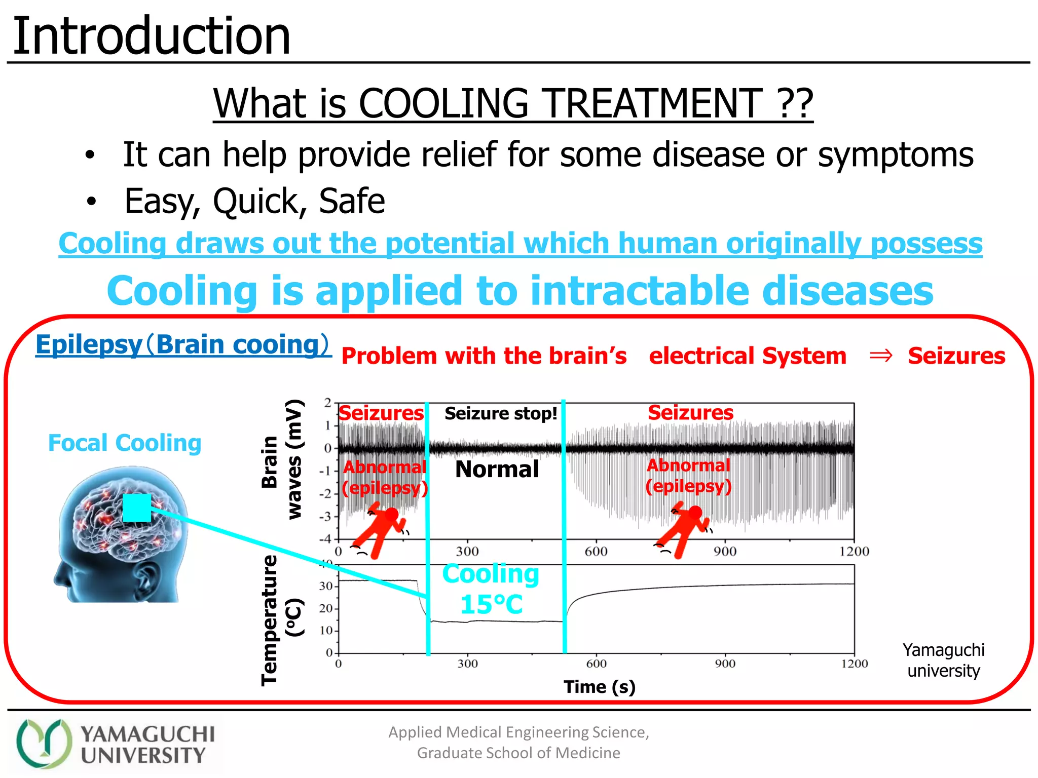
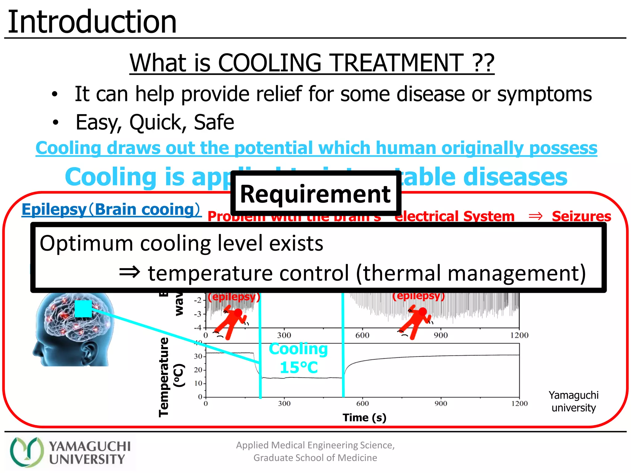
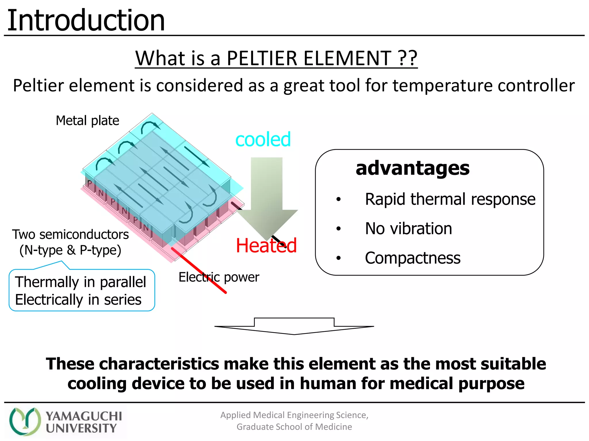

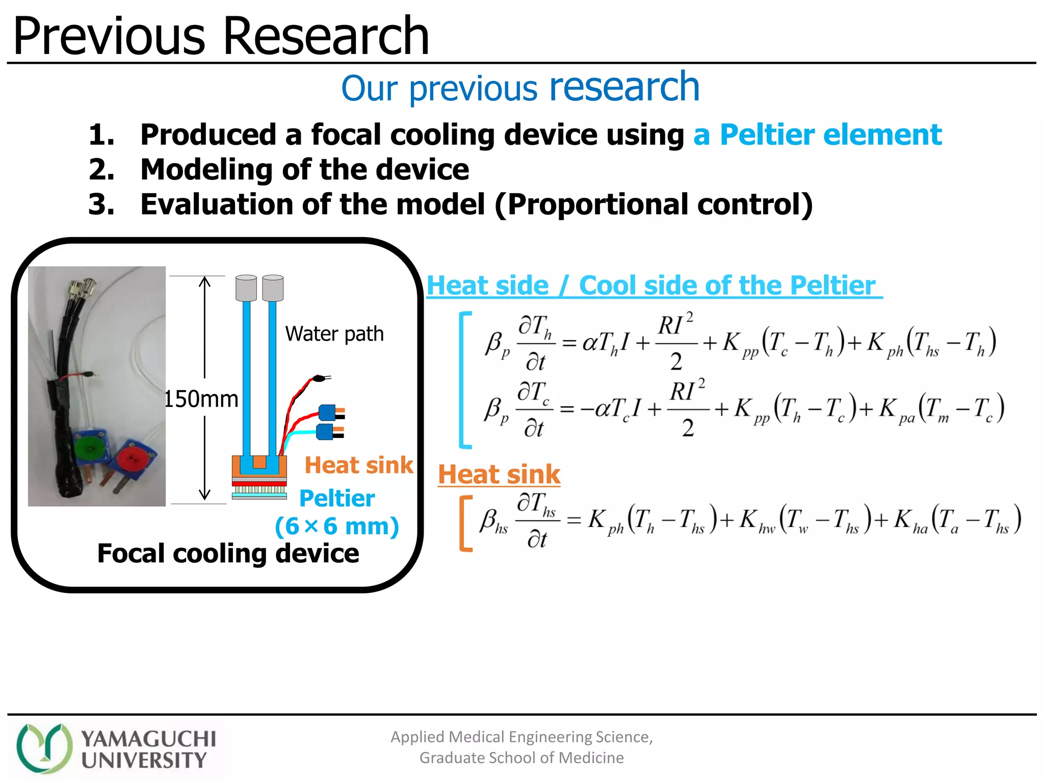
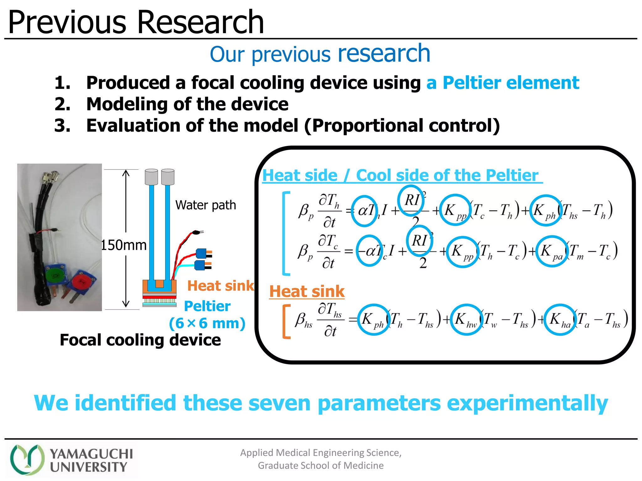
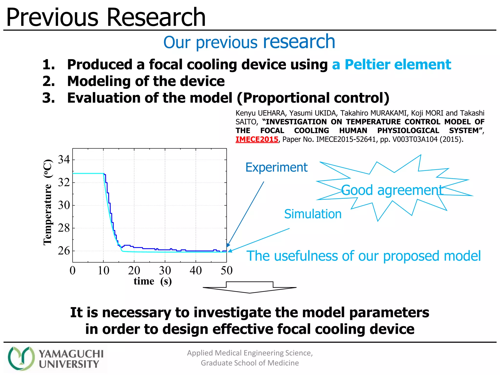


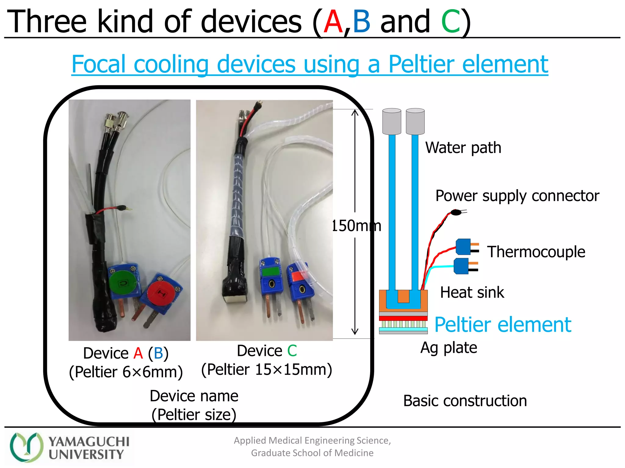
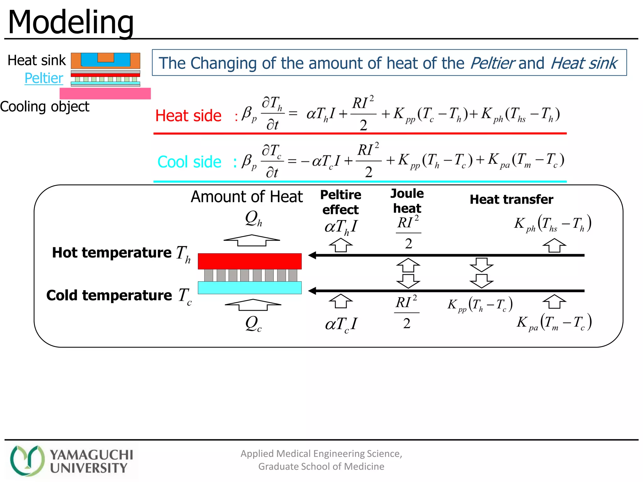
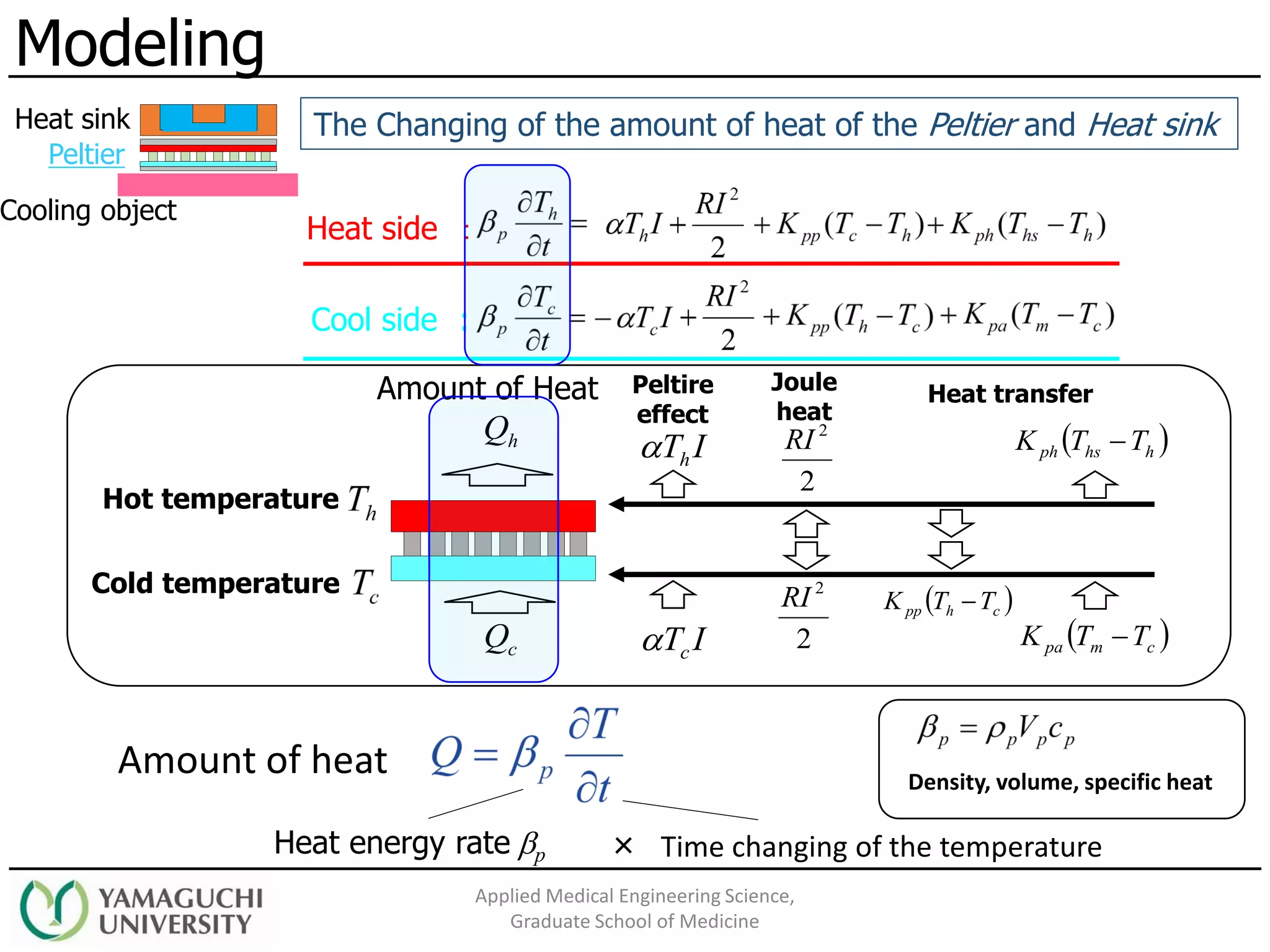
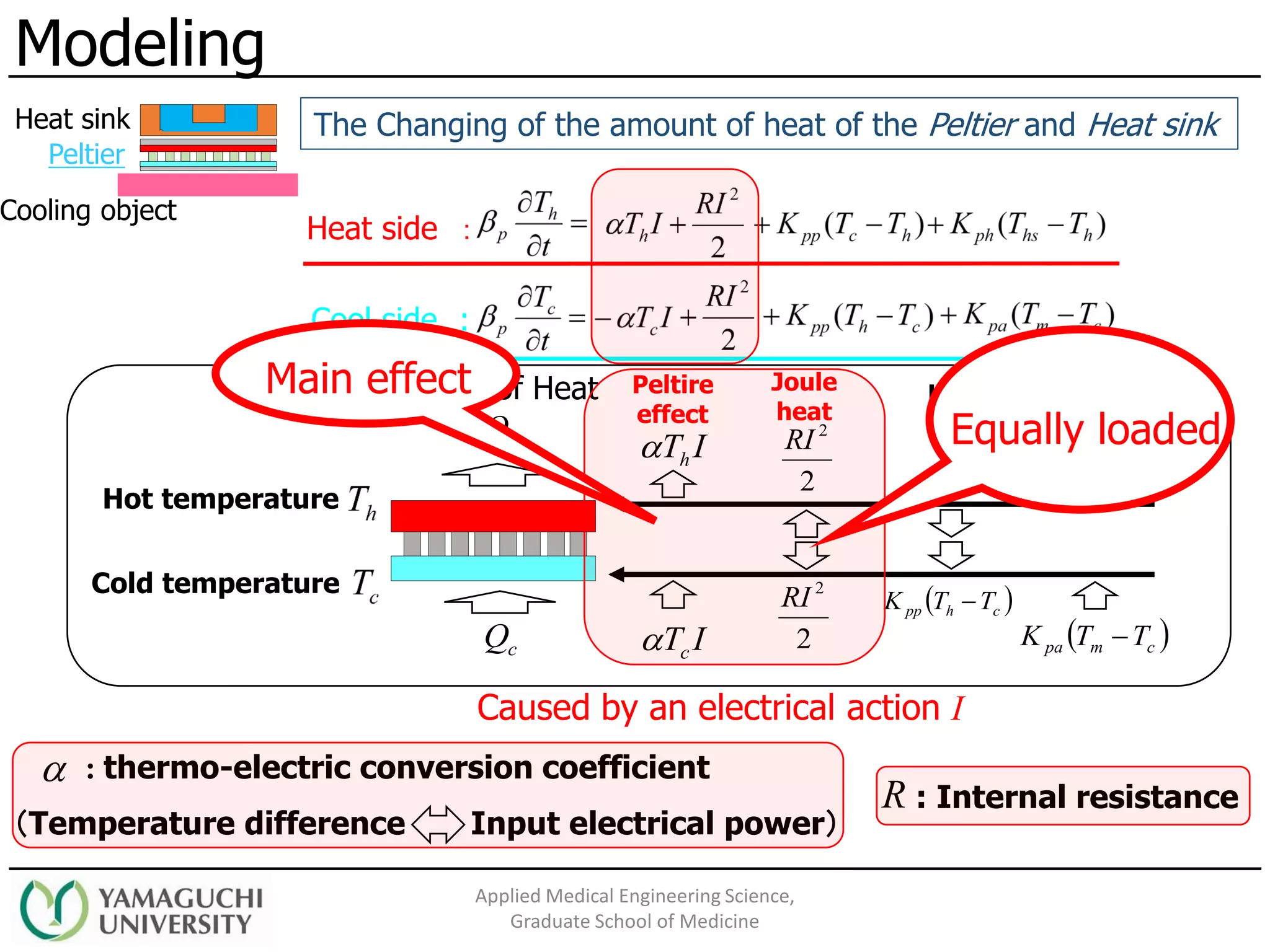
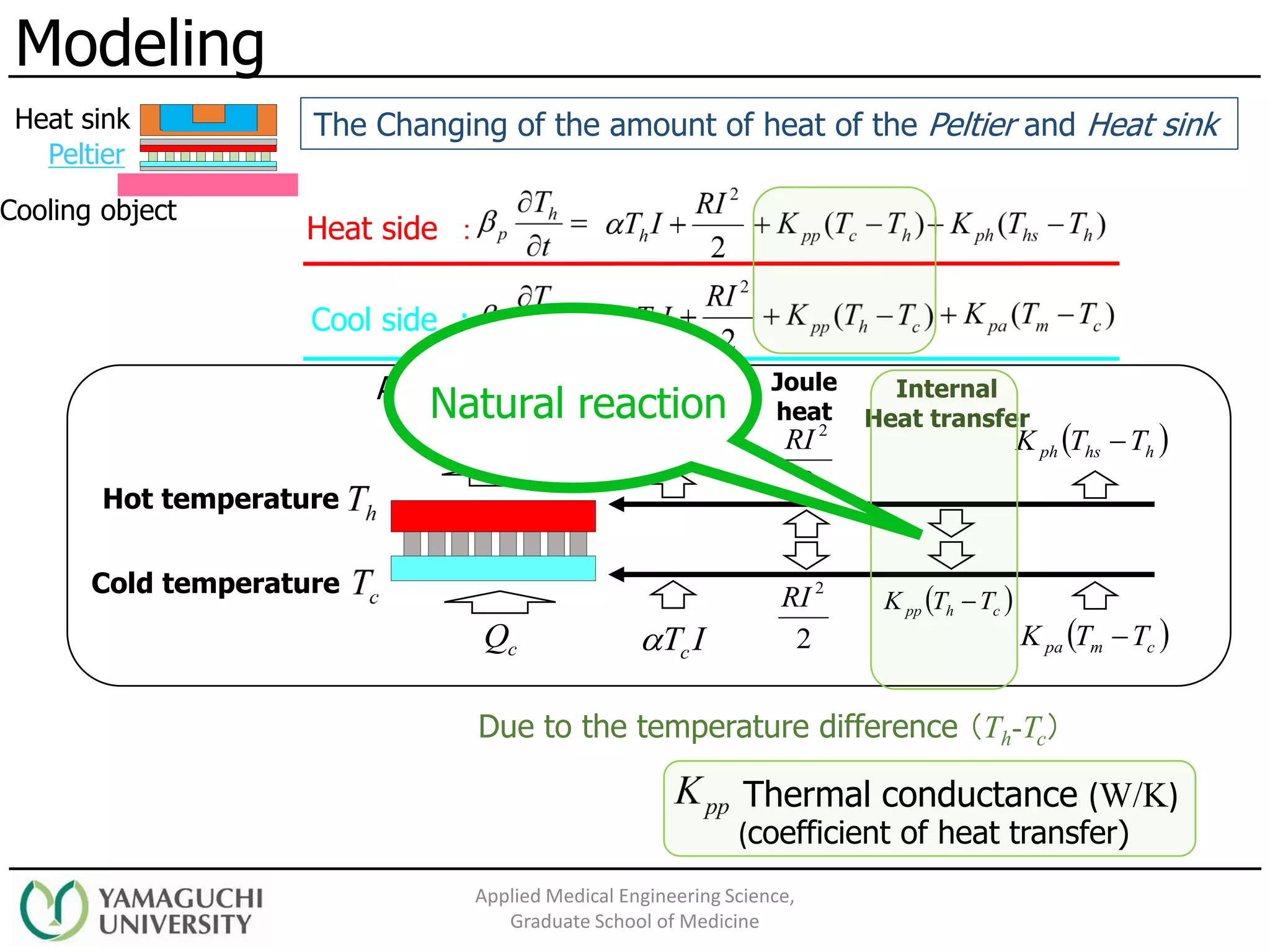
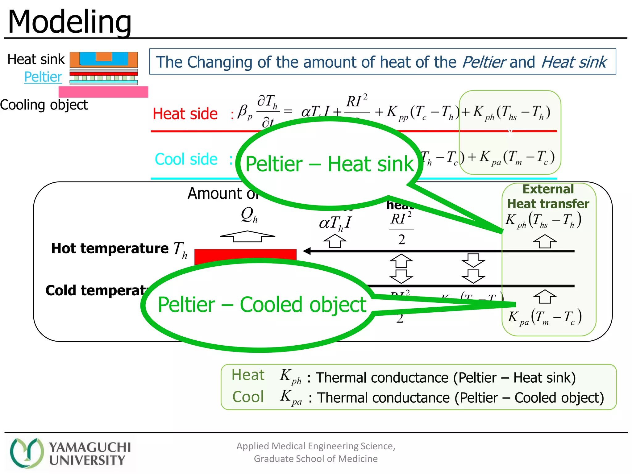


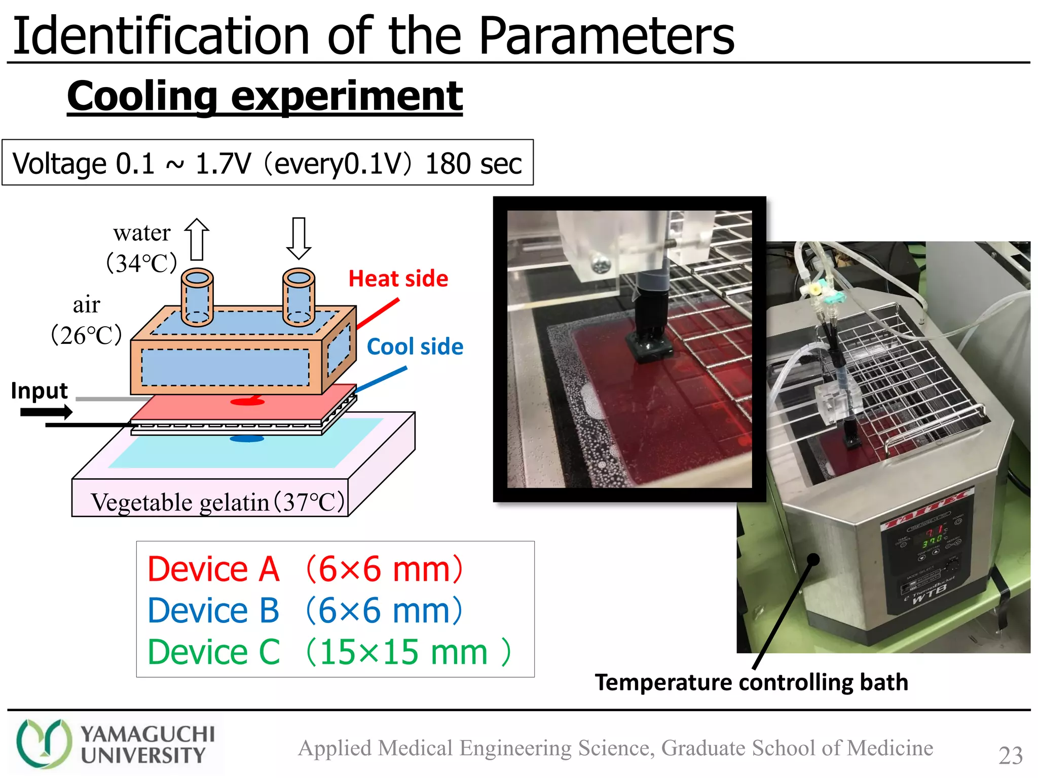
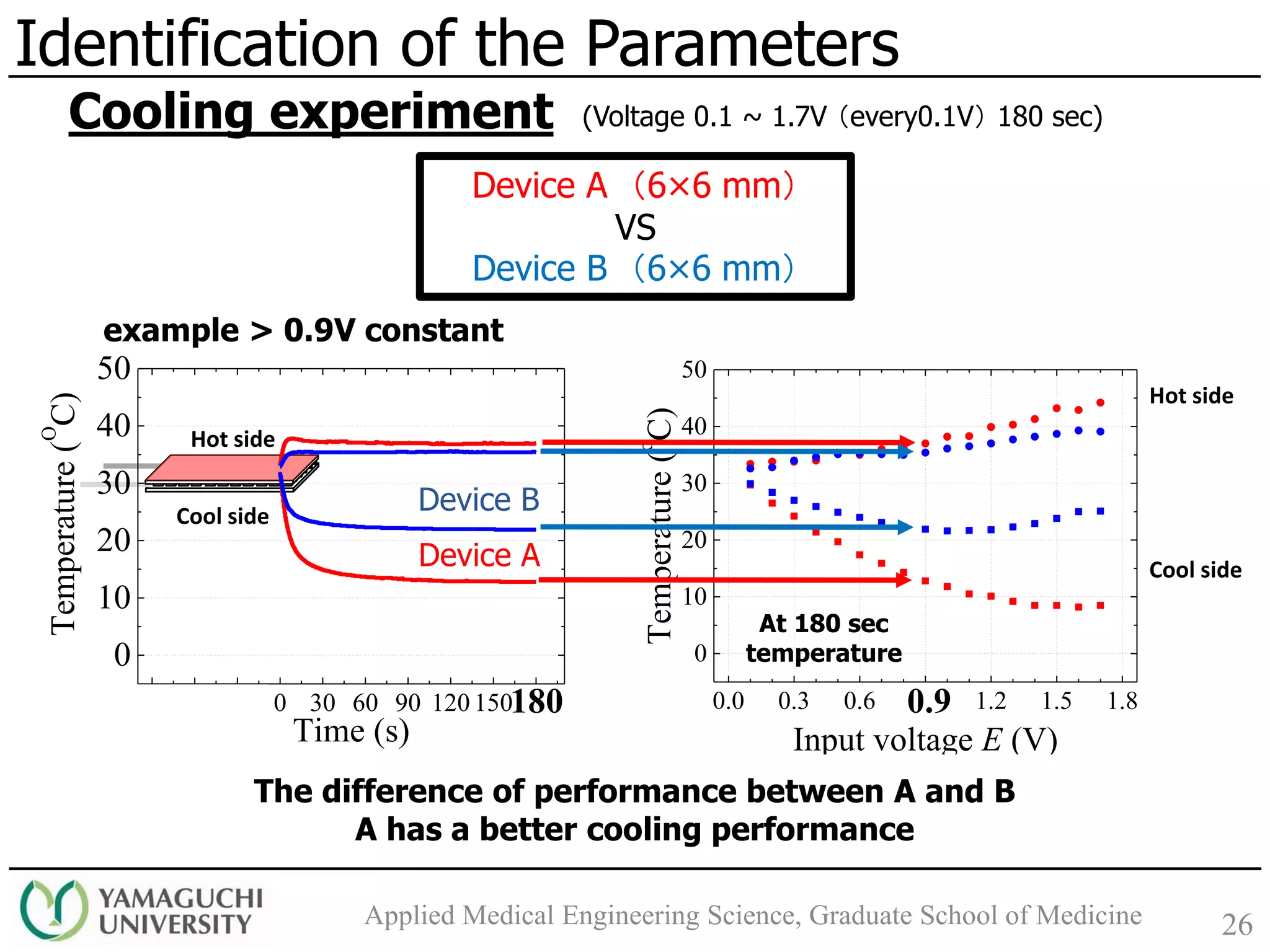
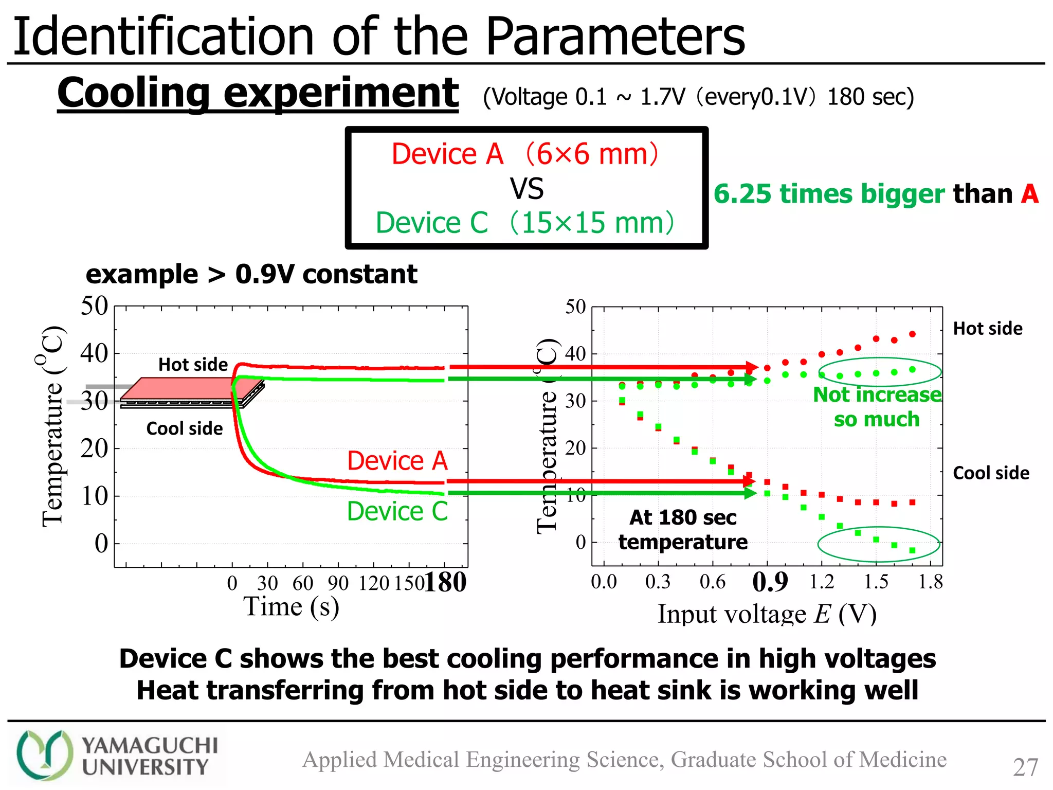
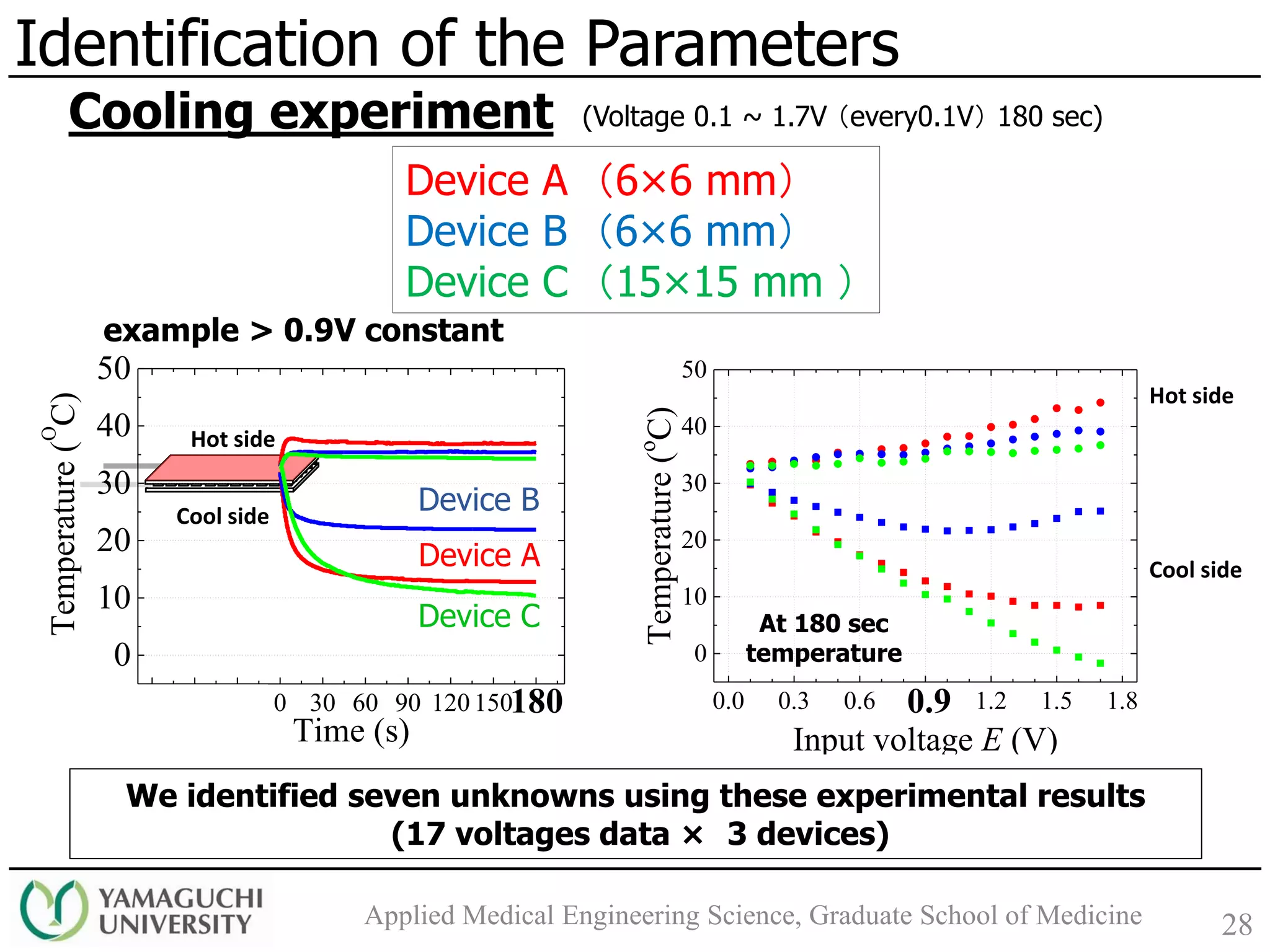

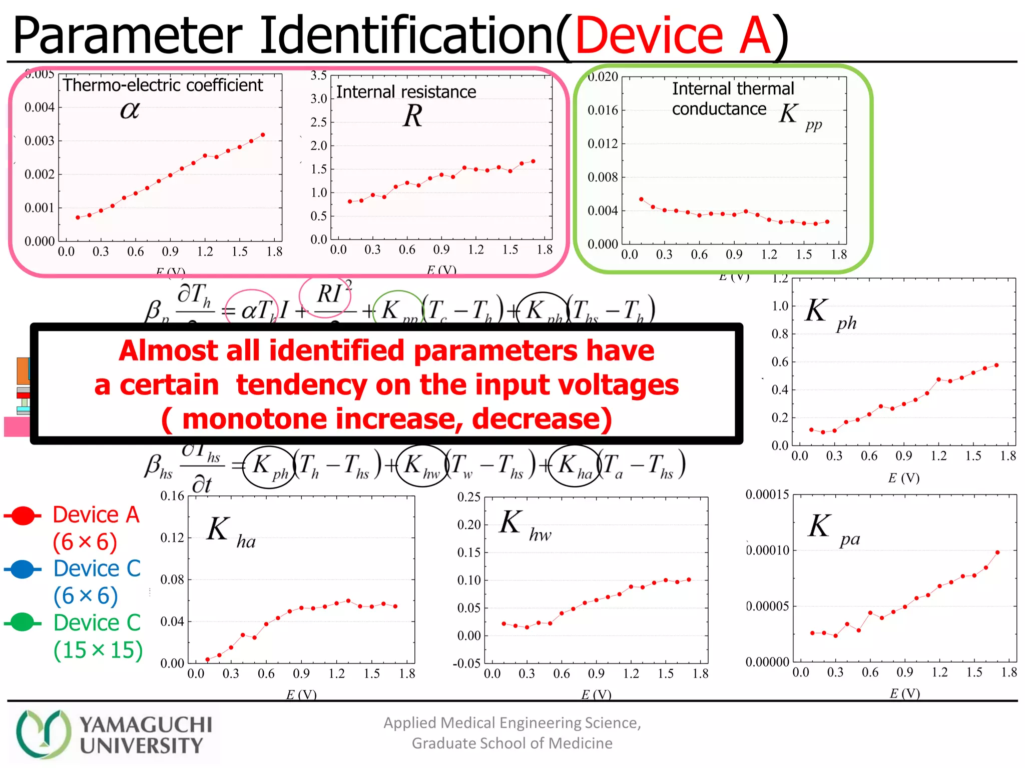
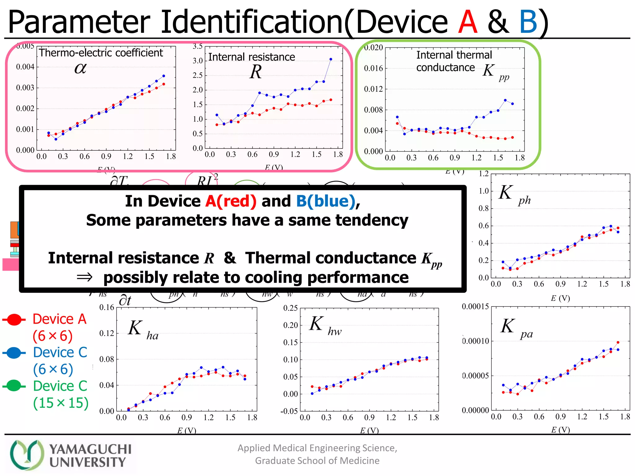
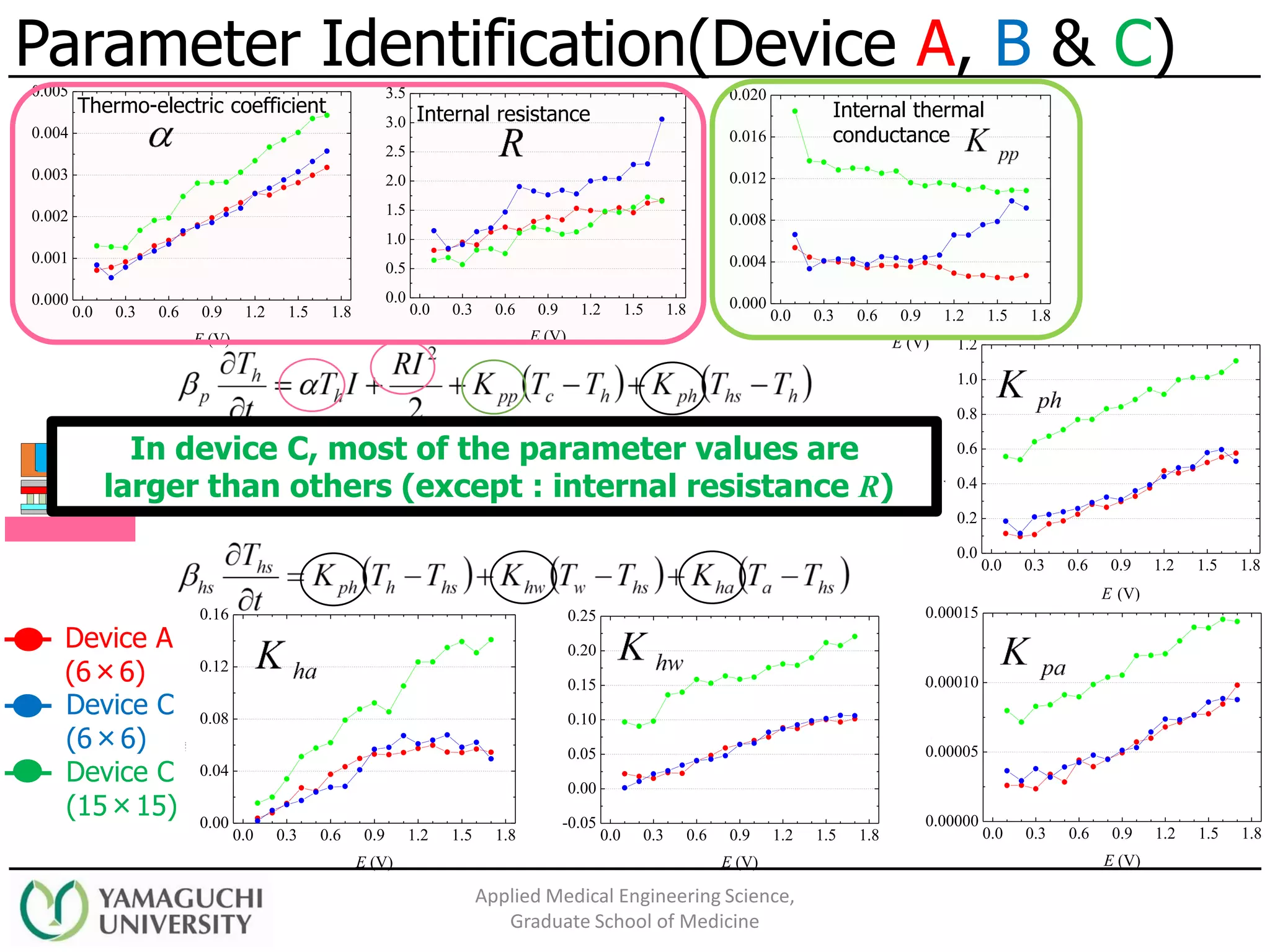

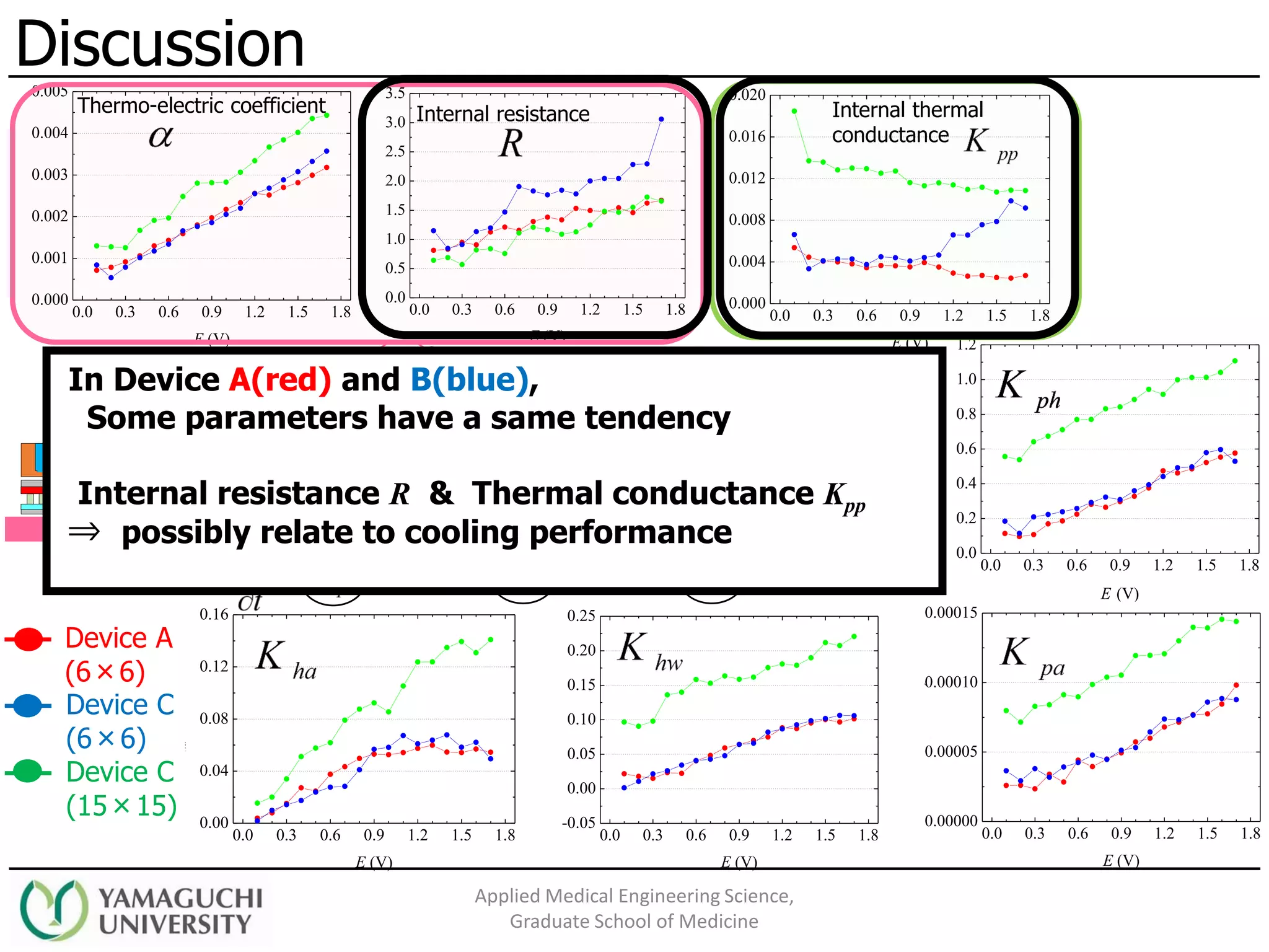
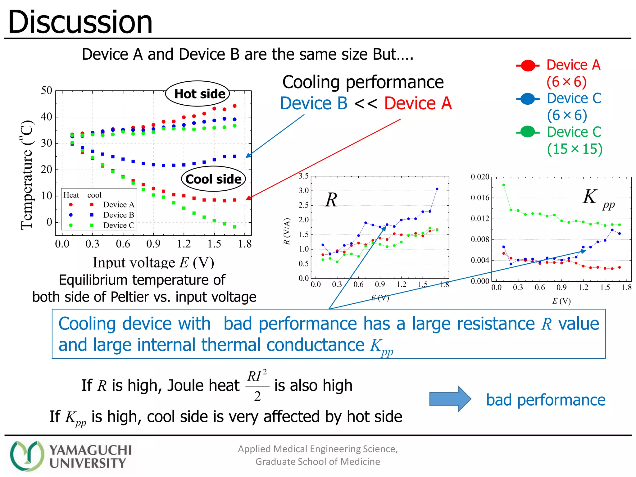

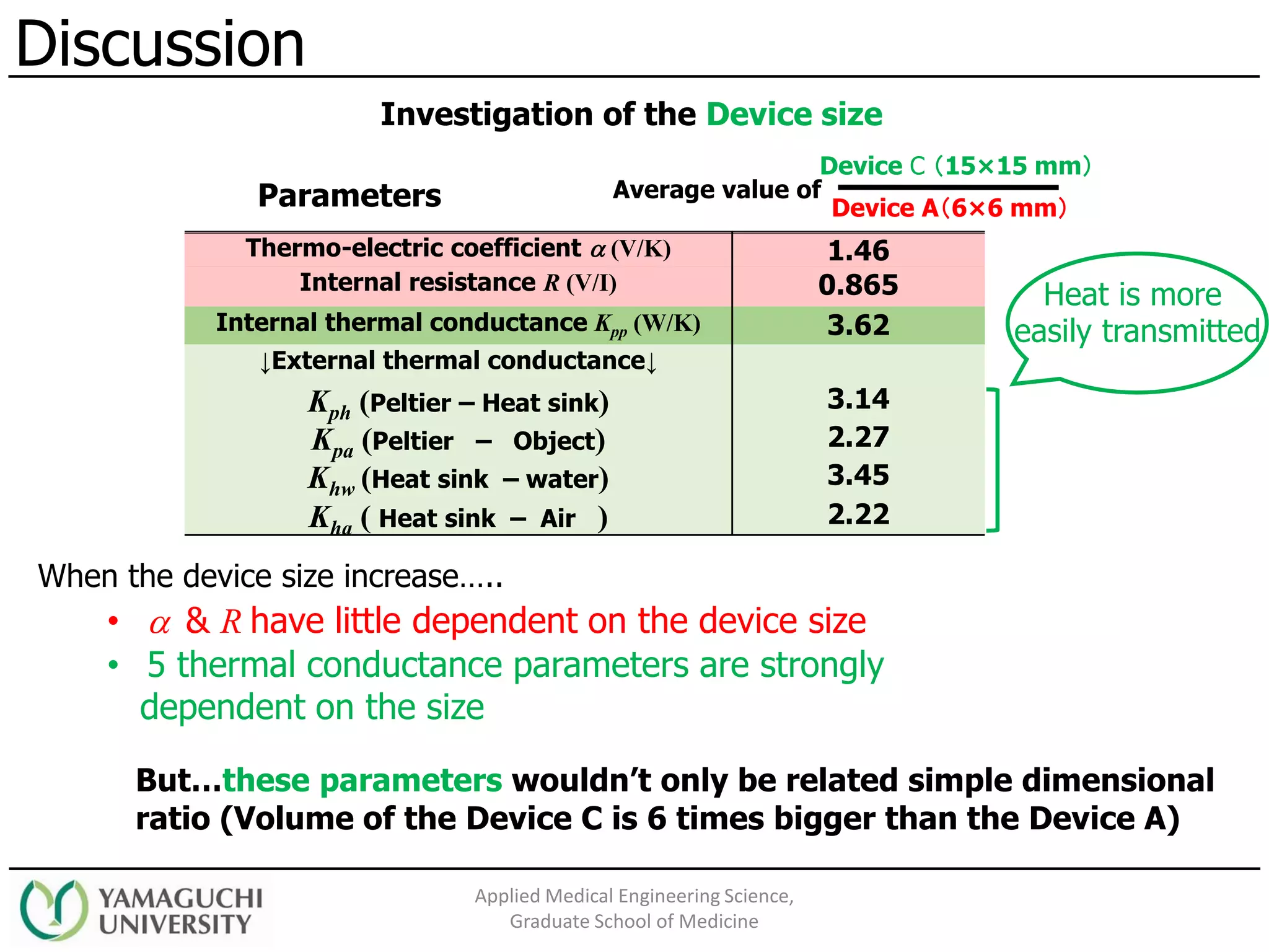
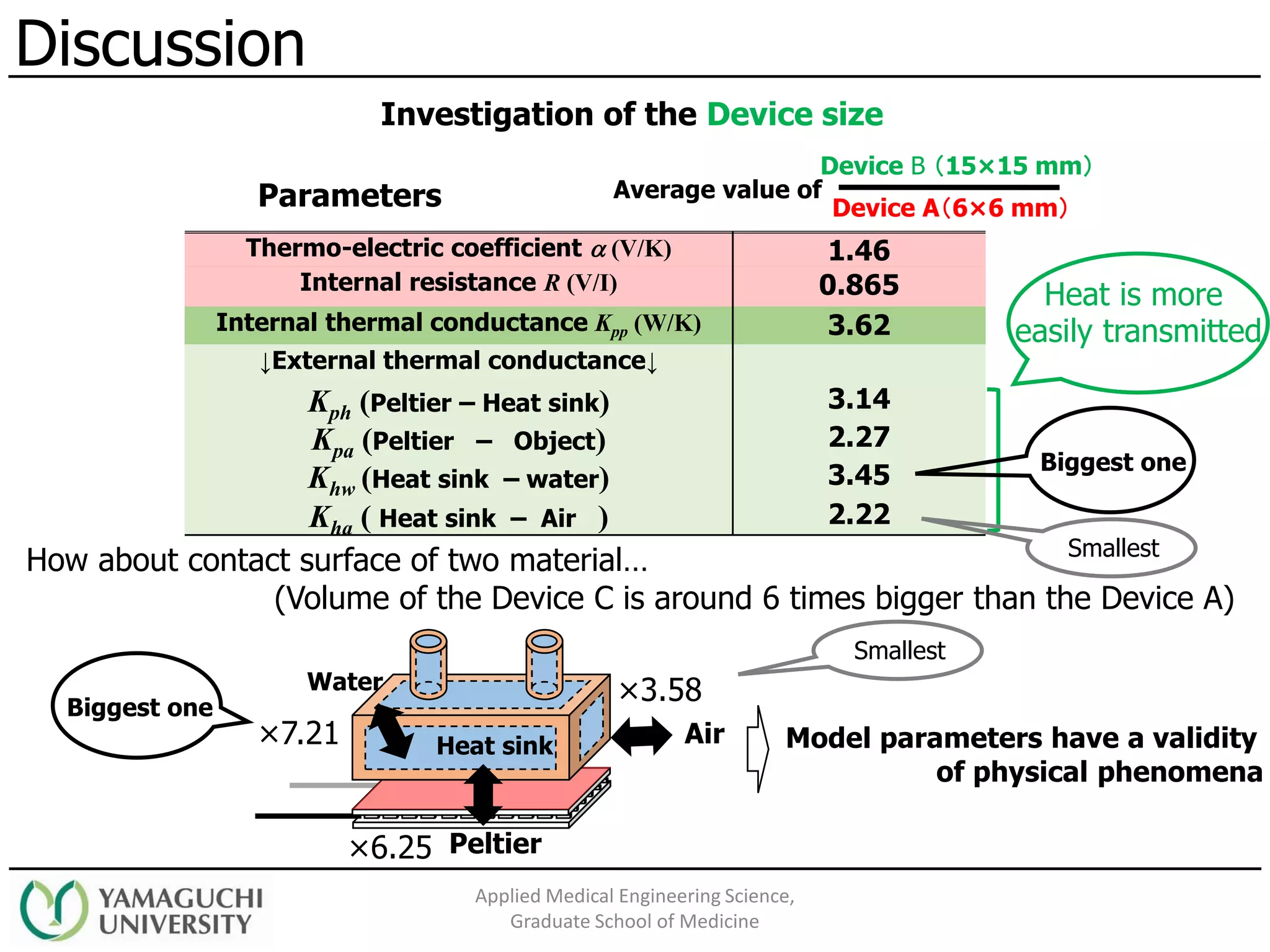
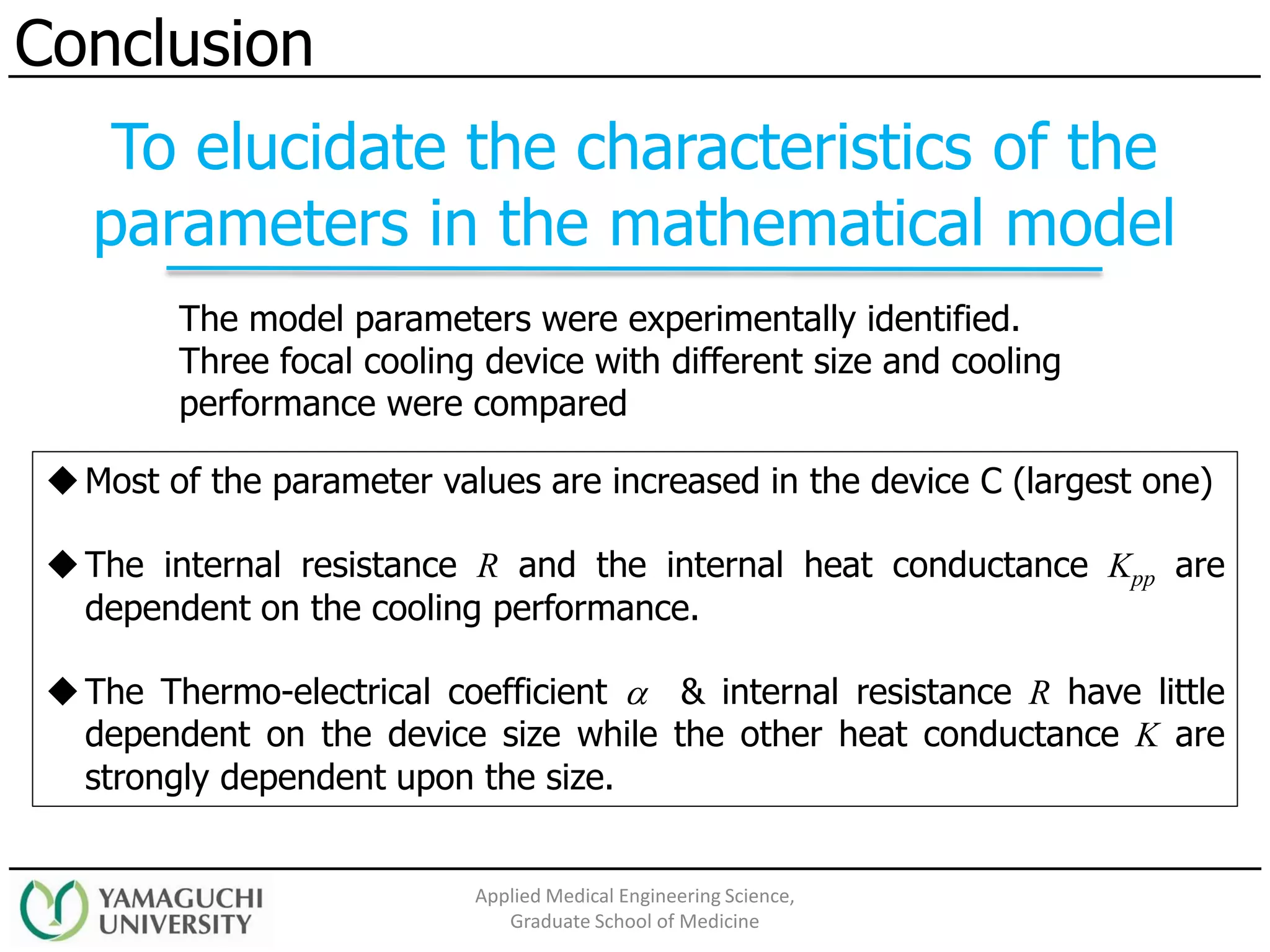

This document presents a study on a focal cooling device using a Peltier element aimed at providing treatment for epilepsy by regulating brain temperature. It discusses the importance of identifying model parameters for effective design and includes experimental results from three different cooling devices. The findings highlight the connection between performance and device size, emphasizing the need for optimal thermal management in medical applications.


