SlideShare a Scribd company logo
LEP
3.3.01
-11
Heat capacity of metals with Cobra3
PHYWE series of publications • Laboratory Experiments • Physics • © PHYWE SYSTEME GMBH & Co. KG • D-37070 Göttingen 23301-11 1
Fig.1: Experimental set-up for the heat capacity of metals
Related topics
Mixture temperature, boiling point, Dulong Petit’s law, lattice
vibration, internal energy, Debye temperature.
Principle
Heated specimens are placed in a calorimeter filled with water
at low temperature. The heat capacity of the specimen is
determined from the rise in the temperature of the water.
Equipment
Cobra3-BASIC-UNIT 12150.00 1
Power Supply, 12 V- 12151.99 1
RS232-Data Cable 14602.00 1
Software Cobra3 Temperature 14503.61 1
Measurement Module Temperature NiCr-Ni 12104.00 1
Immersion Probe NiCr-Ni 13615.03 1
H-base “Pass” 02009.55 1
Support Rod, Stainless Steel 18/8, 600 mm 02037.00 2
Bosshead 02043.00 2
Universal clamp 37715.00 2
Support ring, with clamp 37701.01 1
Wire gauz with ceramic 33287.01 1
Metal bodies, set of 3 04406.00 3
Calorimeter vessel, 500 ml 04401.10 1
Glass beaker, short, 400 ml 36014.00 1
Glass beaker, short, 600 ml 36015.00 1
Agitator rod 04404.10 1
Pipette, with rubber bulb 64701.00 1
Portable balance JR300 48891.00 1
Butane burner, Labogaz 206 type 32178.00 1
Butane cartridge, C206 47535.00 1
Beads, 200 g 36937.20 1
Fish line, 100 m 02090.00 1
PC, Windows®
95 or higher
Paper tissues
Tasks
1. To determine the specific heat capacity of aluminium, iron
and brass.
2. To verify Dulong Petit’s law with the results of these experi-
ments.
LEP
3.3.01
-11
Heat capacity of metals with Cobra3
23301-11 PHYWE series of publications • Laboratory Experiments • Physics • © PHYWE SYSTEME GMBH & Co. KG • D-37070 Göttingen2
Set-up
The experimental set-up is shown in Fig.1.
Fill a 600 ml glass beaker with water at room temperature as
a reserve vessel for the calorimeter.
Connect the temperature measurement module with the mod-
ule port of the Cobra3 BASIC-UNIT and connect the thermo-
element.
Fill 200 g of water at room temperature (m1) in the calorimeter.
Tie two aluminium test pieces together with fishing line and do
the same with three iron and three brass pieces.
Fill a 400 ml glass beaker with about 300 ml of water.
Immerse all the metallic bodies in this water bath using a uni-
versal clamp to avoid that the metallic bodies touch the bot-
tom of the beaker.
Note: The different metallic bodies have to be removable sep-
arately.
Procedure
Bring the water with the metallic bodies to boil.
Select the measurement device temperature in the software.
Start a new measurement and set the parameters according
to Fig. 2.
Calibrate the temperature sensor as follows:
In this experiment the immersion probe should show 100 °C in
boiling water. Hence for calibrating, the probe is kept in the
glass beaker with the boiling water and 100 °C is entered as
value.
The procedure is completed by the buttons ”calibrate” and
”Ok”.
Clicking on ”Continue” shows the measured temperature.
Fig. 2: Measurement parameters
Cool the immersion probe very carefully and then immerse it
in the cold water in the calorimeter vessel.
Start the measurement and measure the temperature of the
water in the calorimeter for about 5 seconds.
Take the metallic bodies of one type (e.g. Aluminium) out of
the the boiling water, dry them quickly, put them in the
calorimeter vessel and stir vigorously.
The measurement automatically ends after 60 seconds or can
be terminated by pressing a key. The measured temperatures
are displayed as a function of time immediately (see Fig. 3).
Repeat the procedure for the other metallic bodies (Figs. 4
and 5).
Before doing so, wash the calorimeter with cold water, dry it
and fill it with water again.
Fig. 3: Course of temperature in the calorimeter
For 120 g Aluminium (100 °C) and 200 g water (room-
temperature)
Fig. 4: Course of temperature in the calorimeter
For 180 g Iron (100 °C) and 200 g water (room-temper-
ature)
Fig. 5: Course of temperature in the calorimeter
For 180 g Brass (100 °C) and 200 g water (room-tem-
perature)
LEP
3.3.01
-11
Heat capacity of metals with Cobra3
PHYWE series of publications • Laboratory Experiments • Physics • © PHYWE SYSTEME GMBH & Co. KG • D-37070 Göttingen 23301-11 3
Theory and evaluation
The heat capacity C of a substance is defined as the quotient
of the quantity of heat absorbed ␦Q and the change in tem-
perature dT.
(1)
and is proportional to the mass of the heated substance.
(2)
is the specific heat capacity.
The quantity of heat absorbed ␦Q depends on the conditions
prevailing as the temperature rises, and a differentiation is
made in particular between heat capacity CV at constant vol-
ume V and heat capacity Cp at constant pressure p.
In accordance with the First Law of Thermodynamics (U = inter-
nal energy),
␦Q = dU + pdV (3)
Cp is always greater than CV. In the case of solids, the change
in volume is so small that we can write
Cp Ӎ CV
CV can be calculated from the change in internal energy with
temperature in accordance with (1) and (3):
(4)
The internal energy U in a solid is essentially the result of lat-
tice vibrations caused by heat.
Fig. 6: Molar heat capacity of a solid in accordance with
Debye’s approximation.
According to Debye’s theory, which considers lattice vibrations
up to a limiting frequency ␯D, the heat capacity is given by
(5)
= 3 Nk · D (T/⍜)
where z = h~/kT,
0 = h␯D/k, called the Debye temperature
h = Planck’s constant,
k = Boltzmann constant,
N = number of atoms in the volume considered.
D (T/⍜) is called the Debye function.
For large values of T/⍜ the upper integration limit is small, the
integrand can be expanded and we obtain the law of Dulong
and Petit:
CV = 3 Nk
We thus obtain the molar heat capacity
Cm = 3 NL · k = 3R = 24.94 J/K (6)
where NL is the Loschmidt number and R the gas constant.
Debye temperature:
Aluminium: 419 K Copper: 335 K
Iron: 462 K Zinc: 100 K
For the evaluation, the heat capacity is assumed to be con-
stant in the temperature range considered.
After the metallic bodies at temperature T2 (=100°C) are put in
the cold water at temperature T1, the mixture in the calorime-
ter has a temperature Tm which results from the energy bal-
ance.
The temperatures before and after heat sharing are not con-
stant because of the exchange of heat with the surroundings.
For the evaluation select the appropriate scale for the temper-
ature axis by adapting the ”display options” in the ”measure-
ment” menu. Enlarge the graph to full screen size and use the
function ”measure” to determine the start temperature T1 and
the mixture temperature Tm with the help of the cursor lines
(Figs. 3-5).
The difference in temperature is also available.
The specific heat capacity of the different materials is
obtained from the energy balance as follows:
where
C = 80 J/K = heat capacity of the calorimeter
C = 4.19 J/gK = specific heat capacity of water
m1 = 200 g = mass of water
m2,1 = 120 g = mass of the aluminium bodies
m2,2 = 180 g = mass of the iron or brass bodies
C2 ϭ
1C ϩ c1m1 2 · 1T1 Ϫ Tm 2
m2 · 1Tm Ϫ T2 2
Cu 1T2 ϭ 3 Nk
a
T
⍜ b
3
· 3Ύ
⍜>T
0
z
4
e
z
dz
1e
z
Ϫ 122
CV ϭ
a
␦U
␦T bV
c ϭ
C
m
C ϭ
dQ
dT
LEP
3.3.01
-11
Heat capacity of metals with Cobra3
23301-11 PHYWE series of publications • Laboratory Experiments • Physics • © PHYWE SYSTEME GMBH & Co. KG • D-37070 Göttingen4
Tab.1: Typical measurement example of the heat capacity
The measured values (Tab.1) of the heat capacity correspond
to the values found in literature.
The values of molar heat capacity as measured in the
Experiment also agree well with the theoretical values from
Dulong and Petit`s law (24.94 J/(Mol K)).
Aluminium Iron Brass
T1/°C 21.39 20.38 20.68
Tm/°C 29.78 26.80 26.17
Tm-T1/K 8.39 6.42 5.49
T2-Tm/K 70.23 73.20 73.83
c/J/gK 0.91 0.45 0.38
clit/J/gK 0.896 0.452 0.385
Cm/J/(Mol·K) 24.48 25.13 24.40

More Related Content

What's hot

Heat & Mass Transfer Project
Heat & Mass Transfer ProjectHeat & Mass Transfer Project
Heat & Mass Transfer Project
RachelBurger2
 
Hmt lab manual
Hmt lab manualHmt lab manual
Heat transfer(HT) lab manual
Heat transfer(HT) lab manualHeat transfer(HT) lab manual
Heat transfer(HT) lab manual
nmahi96
 
Heat 1
Heat 1Heat 1
Heat Conduction Laboratory
Heat Conduction Laboratory Heat Conduction Laboratory
Heat Conduction Laboratory Hail Munassar
 
Introduction to-bomb-calorimetry
Introduction to-bomb-calorimetryIntroduction to-bomb-calorimetry
Introduction to-bomb-calorimetryIngrid McKenzie
 
Thermal conductivity presentation
Thermal conductivity presentationThermal conductivity presentation
Thermal conductivity presentation
Ross Mayo
 
Thermal conductivity of copper
Thermal conductivity of copperThermal conductivity of copper
Thermal conductivity of copperMidoOoz
 
Experimental investigation of thermal conductivity of the metal
Experimental investigation of thermal conductivity of the metalExperimental investigation of thermal conductivity of the metal
Experimental investigation of thermal conductivity of the metal
Dhrumil patel
 
Linear heat conduction
Linear heat conductionLinear heat conduction
Linear heat conduction
Aree Salah
 
determination of thermal conductivity
determination of thermal conductivitydetermination of thermal conductivity
determination of thermal conductivity
Anjali Sudhakar
 
Ht 7
Ht 7Ht 7
Bomb Calorimeter
Bomb Calorimeter Bomb Calorimeter
Bomb Calorimeter
Shaikh Alam
 
Thermogravimetric analysis
Thermogravimetric analysisThermogravimetric analysis
Thermogravimetric analysis
Suresh Selvaraj
 
Thermal Conductivity
Thermal ConductivityThermal Conductivity
Thermal Conductivity
talatameen42
 
Thermal transfer Characteristics of TCM
Thermal transfer Characteristics of TCMThermal transfer Characteristics of TCM
Thermal transfer Characteristics of TCMjlrapter
 
Heat loss in bare and lagged pipes
Heat loss in bare and lagged pipesHeat loss in bare and lagged pipes
Heat loss in bare and lagged pipes
Nicely Jane Eleccion
 

What's hot (20)

Heat & Mass Transfer Project
Heat & Mass Transfer ProjectHeat & Mass Transfer Project
Heat & Mass Transfer Project
 
Hmt lab manual
Hmt lab manualHmt lab manual
Hmt lab manual
 
Heat transfer(HT) lab manual
Heat transfer(HT) lab manualHeat transfer(HT) lab manual
Heat transfer(HT) lab manual
 
Heat 1
Heat 1Heat 1
Heat 1
 
Heat Conduction Laboratory
Heat Conduction Laboratory Heat Conduction Laboratory
Heat Conduction Laboratory
 
Introduction to-bomb-calorimetry
Introduction to-bomb-calorimetryIntroduction to-bomb-calorimetry
Introduction to-bomb-calorimetry
 
Calorimeter
CalorimeterCalorimeter
Calorimeter
 
Thermal conductivity presentation
Thermal conductivity presentationThermal conductivity presentation
Thermal conductivity presentation
 
Thermal conductivity of copper
Thermal conductivity of copperThermal conductivity of copper
Thermal conductivity of copper
 
Experimental investigation of thermal conductivity of the metal
Experimental investigation of thermal conductivity of the metalExperimental investigation of thermal conductivity of the metal
Experimental investigation of thermal conductivity of the metal
 
Linear heat conduction
Linear heat conductionLinear heat conduction
Linear heat conduction
 
Calorimeter
CalorimeterCalorimeter
Calorimeter
 
determination of thermal conductivity
determination of thermal conductivitydetermination of thermal conductivity
determination of thermal conductivity
 
Ht 7
Ht 7Ht 7
Ht 7
 
Bomb Calorimeter
Bomb Calorimeter Bomb Calorimeter
Bomb Calorimeter
 
Thermogravimetric analysis
Thermogravimetric analysisThermogravimetric analysis
Thermogravimetric analysis
 
Thermal Conductivity
Thermal ConductivityThermal Conductivity
Thermal Conductivity
 
Temperature
TemperatureTemperature
Temperature
 
Thermal transfer Characteristics of TCM
Thermal transfer Characteristics of TCMThermal transfer Characteristics of TCM
Thermal transfer Characteristics of TCM
 
Heat loss in bare and lagged pipes
Heat loss in bare and lagged pipesHeat loss in bare and lagged pipes
Heat loss in bare and lagged pipes
 

Similar to Cobra 3

Comparison of Calorific Values of Various Fuels from Different Fuel Stations
Comparison of Calorific Values of Various Fuels from Different Fuel StationsComparison of Calorific Values of Various Fuels from Different Fuel Stations
Comparison of Calorific Values of Various Fuels from Different Fuel Stations
researchinventy
 
Lab manuals Heat Transfer Manuals
Lab manuals   Heat Transfer ManualsLab manuals   Heat Transfer Manuals
Lab manuals Heat Transfer Manuals
Dhiraj Dhiman
 
Temperature Measurements
Temperature MeasurementsTemperature Measurements
Temperature Measurements
saahil kshatriya
 
Tempreture measurement
Tempreture measurementTempreture measurement
Tempreture measurement
Ratnadeepsinh Jadeja
 
Temp-meas-sem.pdf
Temp-meas-sem.pdfTemp-meas-sem.pdf
Temp-meas-sem.pdf
elenashahriari
 
Thermocouple Variances
Thermocouple VariancesThermocouple Variances
Thermocouple Variances
Nicole Fields
 
Thermomters
ThermomtersThermomters
Thermomters
Ehab Hegazy
 
L 04(ss)(ia&c) ((ee)nptel)
L 04(ss)(ia&c) ((ee)nptel)L 04(ss)(ia&c) ((ee)nptel)
L 04(ss)(ia&c) ((ee)nptel)
Bharat Sharma
 
MELAB_LesterWheeler
MELAB_LesterWheelerMELAB_LesterWheeler
MELAB_LesterWheelerKevin Lester
 
Zeroth law of thermodynamics
Zeroth law of thermodynamicsZeroth law of thermodynamics
Zeroth law of thermodynamics
MohdAreebQureshi
 
FABRICATION OF EXPERIMENTAL SETUP TO EVALUATE CONVECTIVE HEAT TRANSFER COEFFI...
FABRICATION OF EXPERIMENTAL SETUP TO EVALUATE CONVECTIVE HEAT TRANSFER COEFFI...FABRICATION OF EXPERIMENTAL SETUP TO EVALUATE CONVECTIVE HEAT TRANSFER COEFFI...
FABRICATION OF EXPERIMENTAL SETUP TO EVALUATE CONVECTIVE HEAT TRANSFER COEFFI...
Bishal Bhandari
 
Experimental and Analytical Performance of Gas Gap Cryogenic Thermal Switch ...
 Experimental and Analytical Performance of Gas Gap Cryogenic Thermal Switch ... Experimental and Analytical Performance of Gas Gap Cryogenic Thermal Switch ...
Experimental and Analytical Performance of Gas Gap Cryogenic Thermal Switch ...
ijsrd.com
 
Analytical Thermal Circuit Fastwarm Cathodes
Analytical Thermal Circuit Fastwarm CathodesAnalytical Thermal Circuit Fastwarm Cathodes
Analytical Thermal Circuit Fastwarm Cathodes
TMD Technologies Limited
 
Ch18 ssm
Ch18 ssmCh18 ssm
Ch18 ssm
Marta Díaz
 
Capter 10 for 9th grade Physics
Capter 10 for 9th grade PhysicsCapter 10 for 9th grade Physics
Capter 10 for 9th grade PhysicsPhysics Amal Sweis
 
Experimental and Theoretical Study of Heat Transfer by Natural Convection of ...
Experimental and Theoretical Study of Heat Transfer by Natural Convection of ...Experimental and Theoretical Study of Heat Transfer by Natural Convection of ...
Experimental and Theoretical Study of Heat Transfer by Natural Convection of ...
International Journal of Engineering Inventions www.ijeijournal.com
 
Instrumentation Lab. Experiment #8 Report: Thermocouples
Instrumentation Lab. Experiment #8 Report: ThermocouplesInstrumentation Lab. Experiment #8 Report: Thermocouples
Instrumentation Lab. Experiment #8 Report: Thermocouples
mohammad zeyad
 
heat
heat heat
Se prod thermo_examples_mst
Se prod thermo_examples_mstSe prod thermo_examples_mst
Se prod thermo_examples_mstVJTI Production
 

Similar to Cobra 3 (20)

Comparison of Calorific Values of Various Fuels from Different Fuel Stations
Comparison of Calorific Values of Various Fuels from Different Fuel StationsComparison of Calorific Values of Various Fuels from Different Fuel Stations
Comparison of Calorific Values of Various Fuels from Different Fuel Stations
 
Lab manuals Heat Transfer Manuals
Lab manuals   Heat Transfer ManualsLab manuals   Heat Transfer Manuals
Lab manuals Heat Transfer Manuals
 
Temperature Measurements
Temperature MeasurementsTemperature Measurements
Temperature Measurements
 
Tempreture measurement
Tempreture measurementTempreture measurement
Tempreture measurement
 
Temp-meas-sem.pdf
Temp-meas-sem.pdfTemp-meas-sem.pdf
Temp-meas-sem.pdf
 
Thermocouple Variances
Thermocouple VariancesThermocouple Variances
Thermocouple Variances
 
Thermomters
ThermomtersThermomters
Thermomters
 
L 04(ss)(ia&c) ((ee)nptel)
L 04(ss)(ia&c) ((ee)nptel)L 04(ss)(ia&c) ((ee)nptel)
L 04(ss)(ia&c) ((ee)nptel)
 
MELAB_LesterWheeler
MELAB_LesterWheelerMELAB_LesterWheeler
MELAB_LesterWheeler
 
Zeroth law of thermodynamics
Zeroth law of thermodynamicsZeroth law of thermodynamics
Zeroth law of thermodynamics
 
FABRICATION OF EXPERIMENTAL SETUP TO EVALUATE CONVECTIVE HEAT TRANSFER COEFFI...
FABRICATION OF EXPERIMENTAL SETUP TO EVALUATE CONVECTIVE HEAT TRANSFER COEFFI...FABRICATION OF EXPERIMENTAL SETUP TO EVALUATE CONVECTIVE HEAT TRANSFER COEFFI...
FABRICATION OF EXPERIMENTAL SETUP TO EVALUATE CONVECTIVE HEAT TRANSFER COEFFI...
 
Experimental and Analytical Performance of Gas Gap Cryogenic Thermal Switch ...
 Experimental and Analytical Performance of Gas Gap Cryogenic Thermal Switch ... Experimental and Analytical Performance of Gas Gap Cryogenic Thermal Switch ...
Experimental and Analytical Performance of Gas Gap Cryogenic Thermal Switch ...
 
Analytical Thermal Circuit Fastwarm Cathodes
Analytical Thermal Circuit Fastwarm CathodesAnalytical Thermal Circuit Fastwarm Cathodes
Analytical Thermal Circuit Fastwarm Cathodes
 
Ch18 ssm
Ch18 ssmCh18 ssm
Ch18 ssm
 
Capter 10 for 9th grade Physics
Capter 10 for 9th grade PhysicsCapter 10 for 9th grade Physics
Capter 10 for 9th grade Physics
 
Experimental and Theoretical Study of Heat Transfer by Natural Convection of ...
Experimental and Theoretical Study of Heat Transfer by Natural Convection of ...Experimental and Theoretical Study of Heat Transfer by Natural Convection of ...
Experimental and Theoretical Study of Heat Transfer by Natural Convection of ...
 
Instrumentation Lab. Experiment #8 Report: Thermocouples
Instrumentation Lab. Experiment #8 Report: ThermocouplesInstrumentation Lab. Experiment #8 Report: Thermocouples
Instrumentation Lab. Experiment #8 Report: Thermocouples
 
heat
heat heat
heat
 
Se prod thermo_examples_mst
Se prod thermo_examples_mstSe prod thermo_examples_mst
Se prod thermo_examples_mst
 
Course of mesurement
Course of mesurementCourse of mesurement
Course of mesurement
 

Cobra 3

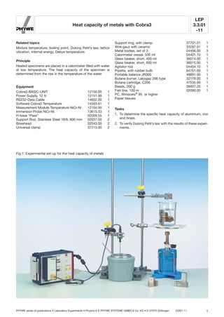
  • 1. LEP 3.3.01 -11 Heat capacity of metals with Cobra3 PHYWE series of publications • Laboratory Experiments • Physics • © PHYWE SYSTEME GMBH & Co. KG • D-37070 Göttingen 23301-11 1 Fig.1: Experimental set-up for the heat capacity of metals Related topics Mixture temperature, boiling point, Dulong Petit’s law, lattice vibration, internal energy, Debye temperature. Principle Heated specimens are placed in a calorimeter filled with water at low temperature. The heat capacity of the specimen is determined from the rise in the temperature of the water. Equipment Cobra3-BASIC-UNIT 12150.00 1 Power Supply, 12 V- 12151.99 1 RS232-Data Cable 14602.00 1 Software Cobra3 Temperature 14503.61 1 Measurement Module Temperature NiCr-Ni 12104.00 1 Immersion Probe NiCr-Ni 13615.03 1 H-base “Pass” 02009.55 1 Support Rod, Stainless Steel 18/8, 600 mm 02037.00 2 Bosshead 02043.00 2 Universal clamp 37715.00 2 Support ring, with clamp 37701.01 1 Wire gauz with ceramic 33287.01 1 Metal bodies, set of 3 04406.00 3 Calorimeter vessel, 500 ml 04401.10 1 Glass beaker, short, 400 ml 36014.00 1 Glass beaker, short, 600 ml 36015.00 1 Agitator rod 04404.10 1 Pipette, with rubber bulb 64701.00 1 Portable balance JR300 48891.00 1 Butane burner, Labogaz 206 type 32178.00 1 Butane cartridge, C206 47535.00 1 Beads, 200 g 36937.20 1 Fish line, 100 m 02090.00 1 PC, Windows® 95 or higher Paper tissues Tasks 1. To determine the specific heat capacity of aluminium, iron and brass. 2. To verify Dulong Petit’s law with the results of these experi- ments.
  • 2. LEP 3.3.01 -11 Heat capacity of metals with Cobra3 23301-11 PHYWE series of publications • Laboratory Experiments • Physics • © PHYWE SYSTEME GMBH & Co. KG • D-37070 Göttingen2 Set-up The experimental set-up is shown in Fig.1. Fill a 600 ml glass beaker with water at room temperature as a reserve vessel for the calorimeter. Connect the temperature measurement module with the mod- ule port of the Cobra3 BASIC-UNIT and connect the thermo- element. Fill 200 g of water at room temperature (m1) in the calorimeter. Tie two aluminium test pieces together with fishing line and do the same with three iron and three brass pieces. Fill a 400 ml glass beaker with about 300 ml of water. Immerse all the metallic bodies in this water bath using a uni- versal clamp to avoid that the metallic bodies touch the bot- tom of the beaker. Note: The different metallic bodies have to be removable sep- arately. Procedure Bring the water with the metallic bodies to boil. Select the measurement device temperature in the software. Start a new measurement and set the parameters according to Fig. 2. Calibrate the temperature sensor as follows: In this experiment the immersion probe should show 100 °C in boiling water. Hence for calibrating, the probe is kept in the glass beaker with the boiling water and 100 °C is entered as value. The procedure is completed by the buttons ”calibrate” and ”Ok”. Clicking on ”Continue” shows the measured temperature. Fig. 2: Measurement parameters Cool the immersion probe very carefully and then immerse it in the cold water in the calorimeter vessel. Start the measurement and measure the temperature of the water in the calorimeter for about 5 seconds. Take the metallic bodies of one type (e.g. Aluminium) out of the the boiling water, dry them quickly, put them in the calorimeter vessel and stir vigorously. The measurement automatically ends after 60 seconds or can be terminated by pressing a key. The measured temperatures are displayed as a function of time immediately (see Fig. 3). Repeat the procedure for the other metallic bodies (Figs. 4 and 5). Before doing so, wash the calorimeter with cold water, dry it and fill it with water again. Fig. 3: Course of temperature in the calorimeter For 120 g Aluminium (100 °C) and 200 g water (room- temperature) Fig. 4: Course of temperature in the calorimeter For 180 g Iron (100 °C) and 200 g water (room-temper- ature) Fig. 5: Course of temperature in the calorimeter For 180 g Brass (100 °C) and 200 g water (room-tem- perature)
  • 3. LEP 3.3.01 -11 Heat capacity of metals with Cobra3 PHYWE series of publications • Laboratory Experiments • Physics • © PHYWE SYSTEME GMBH & Co. KG • D-37070 Göttingen 23301-11 3 Theory and evaluation The heat capacity C of a substance is defined as the quotient of the quantity of heat absorbed ␦Q and the change in tem- perature dT. (1) and is proportional to the mass of the heated substance. (2) is the specific heat capacity. The quantity of heat absorbed ␦Q depends on the conditions prevailing as the temperature rises, and a differentiation is made in particular between heat capacity CV at constant vol- ume V and heat capacity Cp at constant pressure p. In accordance with the First Law of Thermodynamics (U = inter- nal energy), ␦Q = dU + pdV (3) Cp is always greater than CV. In the case of solids, the change in volume is so small that we can write Cp Ӎ CV CV can be calculated from the change in internal energy with temperature in accordance with (1) and (3): (4) The internal energy U in a solid is essentially the result of lat- tice vibrations caused by heat. Fig. 6: Molar heat capacity of a solid in accordance with Debye’s approximation. According to Debye’s theory, which considers lattice vibrations up to a limiting frequency ␯D, the heat capacity is given by (5) = 3 Nk · D (T/⍜) where z = h~/kT, 0 = h␯D/k, called the Debye temperature h = Planck’s constant, k = Boltzmann constant, N = number of atoms in the volume considered. D (T/⍜) is called the Debye function. For large values of T/⍜ the upper integration limit is small, the integrand can be expanded and we obtain the law of Dulong and Petit: CV = 3 Nk We thus obtain the molar heat capacity Cm = 3 NL · k = 3R = 24.94 J/K (6) where NL is the Loschmidt number and R the gas constant. Debye temperature: Aluminium: 419 K Copper: 335 K Iron: 462 K Zinc: 100 K For the evaluation, the heat capacity is assumed to be con- stant in the temperature range considered. After the metallic bodies at temperature T2 (=100°C) are put in the cold water at temperature T1, the mixture in the calorime- ter has a temperature Tm which results from the energy bal- ance. The temperatures before and after heat sharing are not con- stant because of the exchange of heat with the surroundings. For the evaluation select the appropriate scale for the temper- ature axis by adapting the ”display options” in the ”measure- ment” menu. Enlarge the graph to full screen size and use the function ”measure” to determine the start temperature T1 and the mixture temperature Tm with the help of the cursor lines (Figs. 3-5). The difference in temperature is also available. The specific heat capacity of the different materials is obtained from the energy balance as follows: where C = 80 J/K = heat capacity of the calorimeter C = 4.19 J/gK = specific heat capacity of water m1 = 200 g = mass of water m2,1 = 120 g = mass of the aluminium bodies m2,2 = 180 g = mass of the iron or brass bodies C2 ϭ 1C ϩ c1m1 2 · 1T1 Ϫ Tm 2 m2 · 1Tm Ϫ T2 2 Cu 1T2 ϭ 3 Nk a T ⍜ b 3 · 3Ύ ⍜>T 0 z 4 e z dz 1e z Ϫ 122 CV ϭ a ␦U ␦T bV c ϭ C m C ϭ dQ dT
  • 4. LEP 3.3.01 -11 Heat capacity of metals with Cobra3 23301-11 PHYWE series of publications • Laboratory Experiments • Physics • © PHYWE SYSTEME GMBH & Co. KG • D-37070 Göttingen4 Tab.1: Typical measurement example of the heat capacity The measured values (Tab.1) of the heat capacity correspond to the values found in literature. The values of molar heat capacity as measured in the Experiment also agree well with the theoretical values from Dulong and Petit`s law (24.94 J/(Mol K)). Aluminium Iron Brass T1/°C 21.39 20.38 20.68 Tm/°C 29.78 26.80 26.17 Tm-T1/K 8.39 6.42 5.49 T2-Tm/K 70.23 73.20 73.83 c/J/gK 0.91 0.45 0.38 clit/J/gK 0.896 0.452 0.385 Cm/J/(Mol·K) 24.48 25.13 24.40