1) A separately excited DC motor has separate DC voltage supplies for the field coil and armature coil, allowing independent control of each.
2) Reversing the direction of rotation can be achieved by changing the polarity of either the field voltage or armature voltage, but not both. Reversing the field voltage is generally preferable due to lower field currents.
3) Experiments and MATLAB simulations were conducted to verify the direction of rotation under different polarity combinations of the field and armature voltages. The results supported that changing one or the other voltage reverses rotation, while changing both returns it to the original direction.
VTU Notes for Testing and commissioning of Electrical Equipment Department of Electrical and Electronics Faculty Name: Mrs Veena Bhat Designation: Assistant Professor Subject: Testing and Commissioning of Electrical equipment Semester: VII
VTU Notes for Testing and commissioning of Electrical Equipment Department of Electrical and Electronics Faculty Name: Mrs Veena Bhat Designation: Assistant Professor Subject: Testing and Commissioning of Electrical equipment Semester: VII
Functions and Performance Requirements
Elements of an Excitation System
Types of Excitation Systems
Control and Protection Functions
Modeling of Excitation Systems
The functions of an excitation system are
to provide direct current to the synchronous generator field winding, and
to perform control and protective functions essential to the satisfactory operation of the power system
The performance requirements of the excitation system are determined by
Generator considerations:
supply and adjust field current as the generator output varies within its continuous capability
respond to transient disturbances with field forcing consistent with the generator short term capabilities:
rotor insulation failure due to high field voltage
rotor heating due to high field current
stator heating due to high VAR loading
heating due to excess flux (volts/Hz)
Power system considerations:
contribute to effective control of system voltage and improvement of system stability
Part of Lecture series on EEE-413, Electrical Drives (DC Drives) delivered by me to students of VIII Semester B.E. (Electrical), Session 2018-19.
Z. H. College of Engg. & Technology, Aligarh Muslim University, Aligarh.
Missing materials will be uploaded shortly.
Please comment and feel free to ask anything related. Thanks!
Turbo generator converts mechanical energy into electrical energy.
The Mechanical motion is generated in turbine by using heat in the form of saturated steam.It operates on the fundamental principles ofELECTROMAGNETIC INDUCTION.
Excitation System-The process of generating a magnetic field by means of an electric current is called excitation.
It provides power to the field windings thus produce field for rotor.
three level diode clamp inverter. that converts any type of DC ( rectified, PV cell, battery etc.) to AC supply. we made by mosfet and ardiuno . in this ppt we present the Simulink model of a three-level inverter and the hardware presentation of the inverter.
A synchronous motor is electrically identical with an alternator or AC generator.
A given alternator ( or synchronous machine) can be used as a motor, when driven electrically.
Some characteristic features of a synchronous motor are as follows:
1. It runs either at synchronous speed or not at all i.e. while running it maintains a constant speed. The only way to change its speed is to vary the supply frequency (because NS=120f/P).
2. It is not inherently self-starting. It has to be run up to synchronous (or near synchronous) speed by some means, before it can be synchronized to the supply.
3. It is capable of being operated under a wide range of power factors, both lagging and leading. Hence, it can be used for power correction purposes, in addition to supplying torque to drive loads.
The International Journal of Engineering & Science is aimed at providing a platform for researchers, engineers, scientists, or educators to publish their original research results, to exchange new ideas, to disseminate information in innovative designs, engineering experiences and technological skills. It is also the Journal's objective to promote engineering and technology education. All papers submitted to the Journal will be blind peer-reviewed. Only original articles will be published.
CFD Simulation of By-pass Flow in a HRSG module by R&R Consult.pptxR&R Consult
CFD analysis is incredibly effective at solving mysteries and improving the performance of complex systems!
Here's a great example: At a large natural gas-fired power plant, where they use waste heat to generate steam and energy, they were puzzled that their boiler wasn't producing as much steam as expected.
R&R and Tetra Engineering Group Inc. were asked to solve the issue with reduced steam production.
An inspection had shown that a significant amount of hot flue gas was bypassing the boiler tubes, where the heat was supposed to be transferred.
R&R Consult conducted a CFD analysis, which revealed that 6.3% of the flue gas was bypassing the boiler tubes without transferring heat. The analysis also showed that the flue gas was instead being directed along the sides of the boiler and between the modules that were supposed to capture the heat. This was the cause of the reduced performance.
Based on our results, Tetra Engineering installed covering plates to reduce the bypass flow. This improved the boiler's performance and increased electricity production.
It is always satisfying when we can help solve complex challenges like this. Do your systems also need a check-up or optimization? Give us a call!
Work done in cooperation with James Malloy and David Moelling from Tetra Engineering.
More examples of our work https://www.r-r-consult.dk/en/cases-en/
Welcome to WIPAC Monthly the magazine brought to you by the LinkedIn Group Water Industry Process Automation & Control.
In this month's edition, along with this month's industry news to celebrate the 13 years since the group was created we have articles including
A case study of the used of Advanced Process Control at the Wastewater Treatment works at Lleida in Spain
A look back on an article on smart wastewater networks in order to see how the industry has measured up in the interim around the adoption of Digital Transformation in the Water Industry.
Sachpazis:Terzaghi Bearing Capacity Estimation in simple terms with Calculati...Dr.Costas Sachpazis
Terzaghi's soil bearing capacity theory, developed by Karl Terzaghi, is a fundamental principle in geotechnical engineering used to determine the bearing capacity of shallow foundations. This theory provides a method to calculate the ultimate bearing capacity of soil, which is the maximum load per unit area that the soil can support without undergoing shear failure. The Calculation HTML Code included.
About
Indigenized remote control interface card suitable for MAFI system CCR equipment. Compatible for IDM8000 CCR. Backplane mounted serial and TCP/Ethernet communication module for CCR remote access. IDM 8000 CCR remote control on serial and TCP protocol.
• Remote control: Parallel or serial interface.
• Compatible with MAFI CCR system.
• Compatible with IDM8000 CCR.
• Compatible with Backplane mount serial communication.
• Compatible with commercial and Defence aviation CCR system.
• Remote control system for accessing CCR and allied system over serial or TCP.
• Indigenized local Support/presence in India.
• Easy in configuration using DIP switches.
Technical Specifications
Indigenized remote control interface card suitable for MAFI system CCR equipment. Compatible for IDM8000 CCR. Backplane mounted serial and TCP/Ethernet communication module for CCR remote access. IDM 8000 CCR remote control on serial and TCP protocol.
Key Features
Indigenized remote control interface card suitable for MAFI system CCR equipment. Compatible for IDM8000 CCR. Backplane mounted serial and TCP/Ethernet communication module for CCR remote access. IDM 8000 CCR remote control on serial and TCP protocol.
• Remote control: Parallel or serial interface
• Compatible with MAFI CCR system
• Copatiable with IDM8000 CCR
• Compatible with Backplane mount serial communication.
• Compatible with commercial and Defence aviation CCR system.
• Remote control system for accessing CCR and allied system over serial or TCP.
• Indigenized local Support/presence in India.
Application
• Remote control: Parallel or serial interface.
• Compatible with MAFI CCR system.
• Compatible with IDM8000 CCR.
• Compatible with Backplane mount serial communication.
• Compatible with commercial and Defence aviation CCR system.
• Remote control system for accessing CCR and allied system over serial or TCP.
• Indigenized local Support/presence in India.
• Easy in configuration using DIP switches.
Student information management system project report ii.pdfKamal Acharya
Our project explains about the student management. This project mainly explains the various actions related to student details. This project shows some ease in adding, editing and deleting the student details. It also provides a less time consuming process for viewing, adding, editing and deleting the marks of the students.
Final project report on grocery store management system..pdfKamal Acharya
In today’s fast-changing business environment, it’s extremely important to be able to respond to client needs in the most effective and timely manner. If your customers wish to see your business online and have instant access to your products or services.
Online Grocery Store is an e-commerce website, which retails various grocery products. This project allows viewing various products available enables registered users to purchase desired products instantly using Paytm, UPI payment processor (Instant Pay) and also can place order by using Cash on Delivery (Pay Later) option. This project provides an easy access to Administrators and Managers to view orders placed using Pay Later and Instant Pay options.
In order to develop an e-commerce website, a number of Technologies must be studied and understood. These include multi-tiered architecture, server and client-side scripting techniques, implementation technologies, programming language (such as PHP, HTML, CSS, JavaScript) and MySQL relational databases. This is a project with the objective to develop a basic website where a consumer is provided with a shopping cart website and also to know about the technologies used to develop such a website.
This document will discuss each of the underlying technologies to create and implement an e- commerce website.
Water scarcity is the lack of fresh water resources to meet the standard water demand. There are two type of water scarcity. One is physical. The other is economic water scarcity.
Cosmetic shop management system project report.pdfKamal Acharya
Buying new cosmetic products is difficult. It can even be scary for those who have sensitive skin and are prone to skin trouble. The information needed to alleviate this problem is on the back of each product, but it's thought to interpret those ingredient lists unless you have a background in chemistry.
Instead of buying and hoping for the best, we can use data science to help us predict which products may be good fits for us. It includes various function programs to do the above mentioned tasks.
Data file handling has been effectively used in the program.
The automated cosmetic shop management system should deal with the automation of general workflow and administration process of the shop. The main processes of the system focus on customer's request where the system is able to search the most appropriate products and deliver it to the customers. It should help the employees to quickly identify the list of cosmetic product that have reached the minimum quantity and also keep a track of expired date for each cosmetic product. It should help the employees to find the rack number in which the product is placed.It is also Faster and more efficient way.
NO1 Uk best vashikaran specialist in delhi vashikaran baba near me online vas...Amil Baba Dawood bangali
Contact with Dawood Bhai Just call on +92322-6382012 and we'll help you. We'll solve all your problems within 12 to 24 hours and with 101% guarantee and with astrology systematic. If you want to take any personal or professional advice then also you can call us on +92322-6382012 , ONLINE LOVE PROBLEM & Other all types of Daily Life Problem's.Then CALL or WHATSAPP us on +92322-6382012 and Get all these problems solutions here by Amil Baba DAWOOD BANGALI
#vashikaranspecialist #astrologer #palmistry #amliyaat #taweez #manpasandshadi #horoscope #spiritual #lovelife #lovespell #marriagespell#aamilbabainpakistan #amilbabainkarachi #powerfullblackmagicspell #kalajadumantarspecialist #realamilbaba #AmilbabainPakistan #astrologerincanada #astrologerindubai #lovespellsmaster #kalajaduspecialist #lovespellsthatwork #aamilbabainlahore#blackmagicformarriage #aamilbaba #kalajadu #kalailam #taweez #wazifaexpert #jadumantar #vashikaranspecialist #astrologer #palmistry #amliyaat #taweez #manpasandshadi #horoscope #spiritual #lovelife #lovespell #marriagespell#aamilbabainpakistan #amilbabainkarachi #powerfullblackmagicspell #kalajadumantarspecialist #realamilbaba #AmilbabainPakistan #astrologerincanada #astrologerindubai #lovespellsmaster #kalajaduspecialist #lovespellsthatwork #aamilbabainlahore #blackmagicforlove #blackmagicformarriage #aamilbaba #kalajadu #kalailam #taweez #wazifaexpert #jadumantar #vashikaranspecialist #astrologer #palmistry #amliyaat #taweez #manpasandshadi #horoscope #spiritual #lovelife #lovespell #marriagespell#aamilbabainpakistan #amilbabainkarachi #powerfullblackmagicspell #kalajadumantarspecialist #realamilbaba #AmilbabainPakistan #astrologerincanada #astrologerindubai #lovespellsmaster #kalajaduspecialist #lovespellsthatwork #aamilbabainlahore #Amilbabainuk #amilbabainspain #amilbabaindubai #Amilbabainnorway #amilbabainkrachi #amilbabainlahore #amilbabaingujranwalan #amilbabainislamabad
Industrial Training at Shahjalal Fertilizer Company Limited (SFCL)MdTanvirMahtab2
This presentation is about the working procedure of Shahjalal Fertilizer Company Limited (SFCL). A Govt. owned Company of Bangladesh Chemical Industries Corporation under Ministry of Industries.
Explore the innovative world of trenchless pipe repair with our comprehensive guide, "The Benefits and Techniques of Trenchless Pipe Repair." This document delves into the modern methods of repairing underground pipes without the need for extensive excavation, highlighting the numerous advantages and the latest techniques used in the industry.
Learn about the cost savings, reduced environmental impact, and minimal disruption associated with trenchless technology. Discover detailed explanations of popular techniques such as pipe bursting, cured-in-place pipe (CIPP) lining, and directional drilling. Understand how these methods can be applied to various types of infrastructure, from residential plumbing to large-scale municipal systems.
Ideal for homeowners, contractors, engineers, and anyone interested in modern plumbing solutions, this guide provides valuable insights into why trenchless pipe repair is becoming the preferred choice for pipe rehabilitation. Stay informed about the latest advancements and best practices in the field.
3. P a g e 2 | 9
SEPARATELY EXCITED DC MOTOR
Separately excited DC motors also have both stator and rotor. Stator is the static part of motor,
which consists of the field windings. And the rotor is the moving armature which contains
armature windings or coils. Separately excited dc motor has field coils similar to that of shunt
wound dc motor. The name suggests construction of this type of motor. Usually, for other DC
motors, the field coil and the armature coil both are energized from a single source. The field
of them does not need any separate excitation. But, in separately excited DC motor, separate
supply Provided for excitation of both field coil and armature coil. Figure below shows the
separately excited dc motor.
Here, the field coil & armature coil are energized from two separate DC voltage. Armature
voltage source may be variable but, constant DC voltage is used for energizing the field coil.
So, those coils are electrically isolated from each other in this motor, and this connection is the
specialty of this type of DC motor.
Task-1
For motor operation Observe the direction of rotation under following conditions
➢ change Polarity of IF and keep polarity of VA unchanged
➢ Change the polarity of VA and keep polarity of IF unchanged
➢ Change both polarity of IF and polarity of VA
THORETICAL PART
For a “standard” brushed DC motor, it is easiest to control the rotation of the
motor on a separately excited motor, where the field winding has separate
terminals to the (main) armature winding. This is typically done on a motor
designed for speed control. To reverse the motor, you need to change the polarity
of the supply voltage to either the field winding or the armature winding, but
not both. Generally it is better to reverse the field voltage because the field
current is less than the armature current, so your reversing switchgear is more
lightweight. If you cannot separate the field terminals and armature terminals,
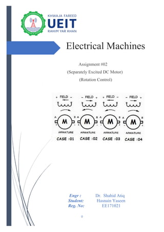
then reversing cannot be done. As below in figure we can check that
4. P a g e 3 | 9
when we change the polarity of Field supply then the rotation of motor become
reverse(CASE :02)because when we change the polarity of Field then the force
that rotate the rotor of the motor acts in opposite direction. When we change the
polarity of of armature voltage then also the rotation of the rotor become
reverse(CASE :03).But when we change the both polarities then rotation of the
motor is the same as in (case :01) because when we change the polarity of both
field and armature then the force that rotate the armature acts in the same
direction as in conventional way(CASE :01).So by comparing CASE:01&CASE:04)
we can say that by change the polarity of both field and armature voltage the
direction of the rotation of motor remain same. Now lets check this theory
practically and by simulation at MATLAB.
Fig .(2.1)
EXPERIMENTAL PART
We check the rotation control of separately excited Dc Motor Experimentally and our final
results are recorded in the table (2.1).
Case :01
When polarity is in conventional way. When we connect the positive terminal of
Armature and IF to the positive of the DC supply and connect the negative end with the
negative end of the supply.
Then we observe that
➢ Field Current (IF) =0.28 with positive sign
➢ Armature Voltage (Va) =101V with positive sign
➢ The direction of the rotation of the rotor of motor is Clockwise.
Case :02
When we change Polarity of IF and keep polarity of VA unchanged.
Then we observe that
➢ Field Current (IF) = -0.27 with negative sign
➢ Armature Voltage (Va) =101V with positive sign
5. P a g e 4 | 9
➢ The direction of the rotation of the rotor of motor is Counter Clockwise.
Case :03
➢ When we Change the polarity of VA and keep polarity of IF unchanged.
Then we observe that
➢ Field Current (IF) = 0.27 with postive sign
➢ Armature Voltage (Va) = -101V with negtive sign
➢ The direction of the rotation of the rotor of motor is Counter Clockwise.
Case :04
When we Change both polarity of IF and polarity of VA.
Then we observe that
➢ Field Current (IF) = -0.26 with negative sign
➢ Armature Voltage (Va) = -101V with negative sign
➢ The direction of the rotation of the rotor of motor is Clockwise.
Table (2.1)
Sr NO:
Field Current (IF)
(A)
Armature Voltage (VA)
(V)
Direction of Rotation
Of Rotor
CASE :01 0.28 101 Clockwise
CASE: 02 -0.27 101 Counter Clockwise
CASE:03 0.27 - 101 Counter Clockwise
CASE:04 -0.26 -101 Clockwise
6. P a g e 5 | 9
MATLAB SIMULATION
CASE:01
When polarity is in conventional way. Then we can observe from graphs that
speed(Clockwise), Field Current & Armature Current all positive.
7. P a g e 6 | 9
CASE:02
When we change Polarity of IF and keep polarity of VA unchanged. Then we observe from
graphs that the speed(Counter Clockwise)& Field current are negative but Armature current
is still positive.
8. P a g e 7 | 9
CASE:03
When we Change the polarity of VA and keep polarity of IF unchanged.Then we can
observe from graphs that speed (Counter Clockwise)&Armature current are negative
but now field current is positive.
9. P a g e 8 | 9
CASE:04
When we Change both polarity of IF and polarity of VA. Then we can observe from
the graphs that Field current & Armature current are negative but now
speed(Clockwise) is positive .
10. P a g e 9 | 9
CONCLUSION:
So we can conclude from our experimental and MATLAB simulation results that
When polarity is in conventional way. Then speed (Clockwise), Field Current &
Armature Current all are positive. When we change Polarity of IF and keep polarity of
VA unchanged. Then the speed (Counter Clockwise)& Field current are negative but
Armature current is still positive. When we Change the polarity of VA and keep polarity
of IF unchanged. Then the speed (Counter Clockwise) &Armature current are negative
but now field current is positive. When we Change both polarity of IF and polarity of
VA. Then the Field current & Armature current are negative but now speed(Clockwise)
is positive .