1. The document discusses fiber modeling approaches for nonlinear modeling of structural components like beams, columns, and shear walls. In the fiber modeling approach, the cross-section is divided into fibers that are assigned uniaxial stress-strain relationships.
2. Material models like the Mander model for concrete and Park model for steel are presented to define the stress-strain relationships in the fibers. Fiber hinges can also be defined to represent coupled axial-flexural behavior.
3. Acceptance criteria like immediate occupancy, life safety, and collapse prevention are defined by points on the force-deformation relationship to evaluate performance.
Introduction of Fawad A. Najam and the course on Performance-Based Seismic Design.
Introduction to Fiber Modeling for nonlinear modeling of structures with emphasis on practical approaches.
Detailing of Fiber Modeling for structural members including beams, columns, and shear walls.
Discussion on shear wall fiber cross-sections and the realistic modeling assumptions.
Introduction to nonlinear modeling of materials with focus on stress-strain relationships for concrete and steel.
Application of fiber hinges and layered shell element in nonlinear modeling of structures.
Establishment of acceptance criteria in hinge models for seismic assessment.
Mander’s Unconfined Concrete model and its implications on tensile and compressive behavior.
Overview of lower-bound and expected material capacities as per ASCE guidelines.
Models for hysteretic behavior including explicit modeling and degradation of backbone curves.
Several hysteresis models detailing energy dissipation under cyclic loading.
Description of models for concrete, including variations suitable for different material behaviors.General guidelines and demonstrations for fiber modeling of beams, columns, and shear walls.
Conclusion and acknowledgment from the presentation.
Fawad A. Najam
Departmentof Structural Engineering
NUST Institute of Civil Engineering (NICE)
National University of Sciences and Technology (NUST)
H-12 Islamabad, Pakistan
Cell: 92-334-5192533, Email: fawad@nice.nust.edu.pk
Credits: 3 + 0
PG 2019
Spring 2020 Semester
Performance-based Seismic Design of Structures
4
Performance-based Seismic Designof Buildings – Semester: Spring 2018 (Fawad A. Najam)
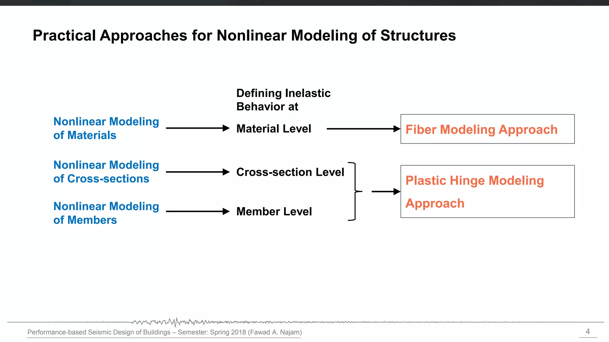
Plastic Hinge Modeling
Approach
Practical Approaches for Nonlinear Modeling of Structures
Nonlinear Modeling
of Materials
Nonlinear Modeling
of Cross-sections
Nonlinear Modeling
of Members
Material Level
Cross-section Level
Member Level
Defining Inelastic
Behavior at
Fiber Modeling Approach
5.
5
Performance-based Seismic Designof Buildings – Semester: Spring 2018 (Fawad A. Najam)
An Introduction to Fiber Modeling Approach for Nonlinear
Modeling of Structural Components
6.
6
Performance-based Seismic Designof Buildings – Semester: Spring 2020 (Fawad A. Najam)
Fiber Modeling Approach
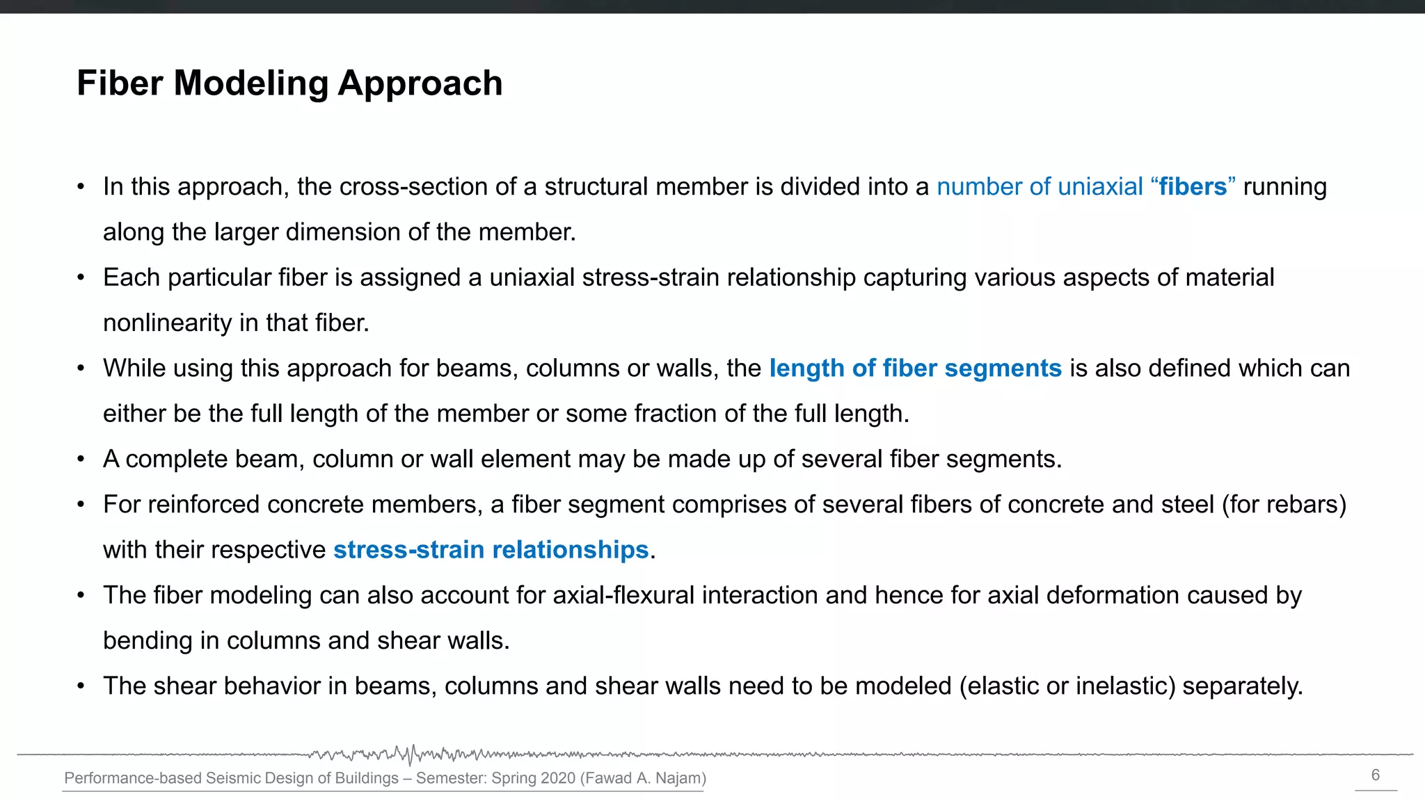
• In this approach, the cross-section of a structural member is divided into a number of uniaxial “fibers” running
along the larger dimension of the member.
• Each particular fiber is assigned a uniaxial stress-strain relationship capturing various aspects of material
nonlinearity in that fiber.
• While using this approach for beams, columns or walls, the length of fiber segments is also defined which can
either be the full length of the member or some fraction of the full length.
• A complete beam, column or wall element may be made up of several fiber segments.
• For reinforced concrete members, a fiber segment comprises of several fibers of concrete and steel (for rebars)
with their respective stress-strain relationships.
• The fiber modeling can also account for axial-flexural interaction and hence for axial deformation caused by
bending in columns and shear walls.
• The shear behavior in beams, columns and shear walls need to be modeled (elastic or inelastic) separately.
7.
7
Performance-based Seismic Designof Buildings – Semester: Spring 2020 (Fawad A. Najam)
Fiber Modeling Approach
• Fiber hinges (P-M3 or P-M2-M3) can be defined, which are a collection of material points over the cross
section.
• Each point represents a tributary area and has its own stress-strain curve.
• Plane sections are assumed to remain planar for the section, which ties together the behavior of the
material points.
• Fiber hinges are often more realistic than force-moment hinges, but are more computationally intensive.
8.
8
Performance-based Seismic Designof Buildings – Semester: Spring 2020 (Fawad A. Najam)
Fiber Model of Reinforced Concrete Beams
(a) Fiber section of a reinforced
concrete beam (Modified from
Powell [2006])
Linear-elastic frame element
Fiber segment (concrete and
steel fibers)
Beam cross-section
(b) Fiber segments at both
ends of a reinforced concrete
beam with Linear-elastic
frame element in-between.
The length of fiber segments
is a small fraction of the total
beam length.
9.
9
Performance-based Seismic Designof Buildings – Semester: Spring 2020 (Fawad A. Najam)
Fiber Model of Reinforced Concrete Beams
• A common assumption for a beam is that there is inelastic bending in only one direction.
• To model bending behavior in the vertical direction, fibers are needed only through the depth of the beam,
as indicated in the figure.
• For horizontal bending an elastic bending stiffness is specified (i.e., an EI value). For vertical bending the
fiber model determines EI. For horizontal bending the model assumes that there is no P-M interaction. It
also assumes that there is no coupling between vertical and lateral bending [Powell 2006].
10.
10
Performance-based Seismic Designof Buildings – Semester: Spring 2020 (Fawad A. Najam)
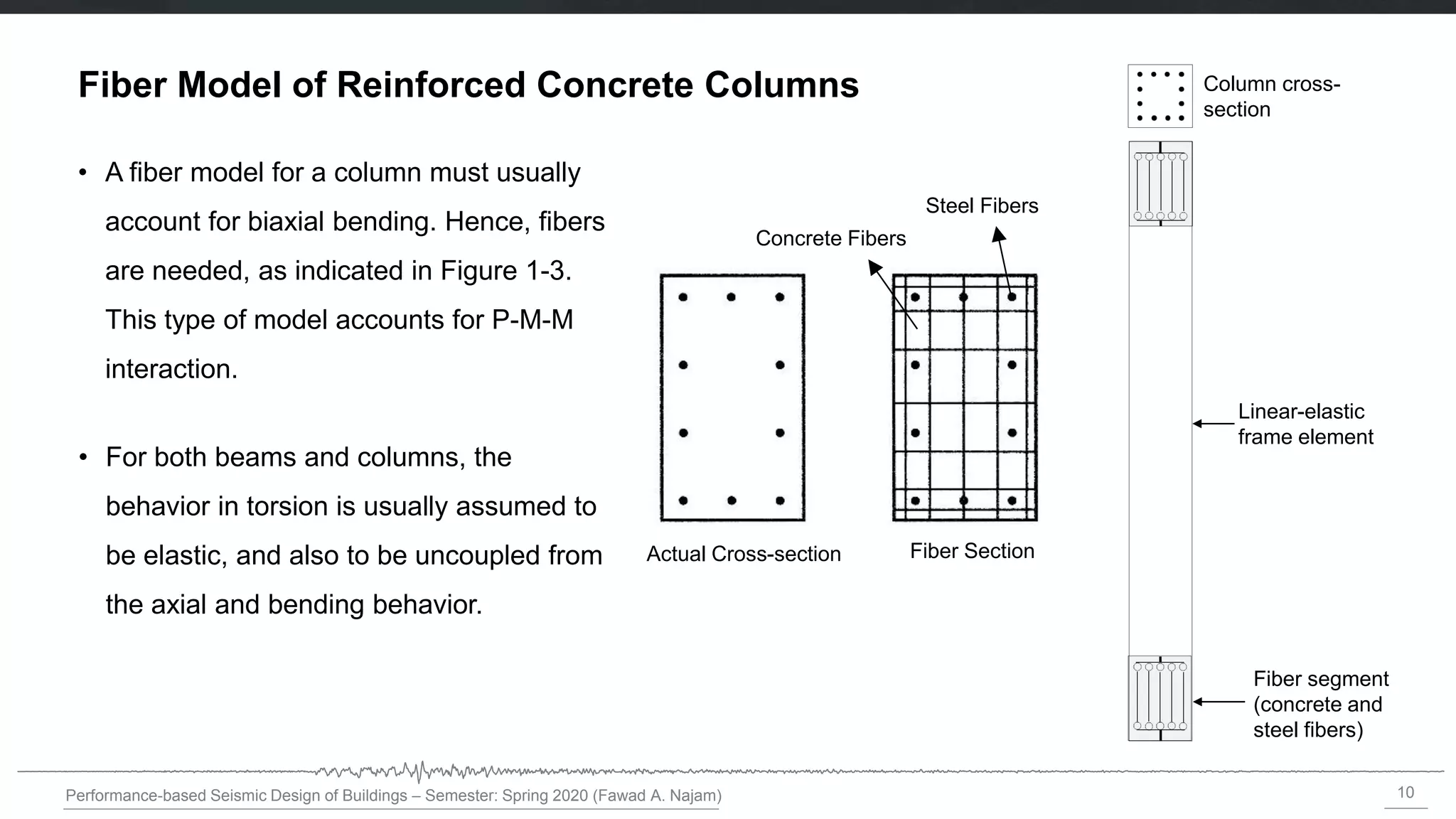
Fiber Model of Reinforced Concrete Columns
Linear-elastic
frame element
Column cross-
section
Fiber segment
(concrete and
steel fibers)
Actual Cross-section Fiber Section
Concrete Fibers
Steel Fibers
• A fiber model for a column must usually
account for biaxial bending. Hence, fibers
are needed, as indicated in Figure 1-3.
This type of model accounts for P-M-M
interaction.
• For both beams and columns, the
behavior in torsion is usually assumed to
be elastic, and also to be uncoupled from
the axial and bending behavior.
11.
11
Performance-based Seismic Designof Buildings – Semester: Spring 2020 (Fawad A. Najam)
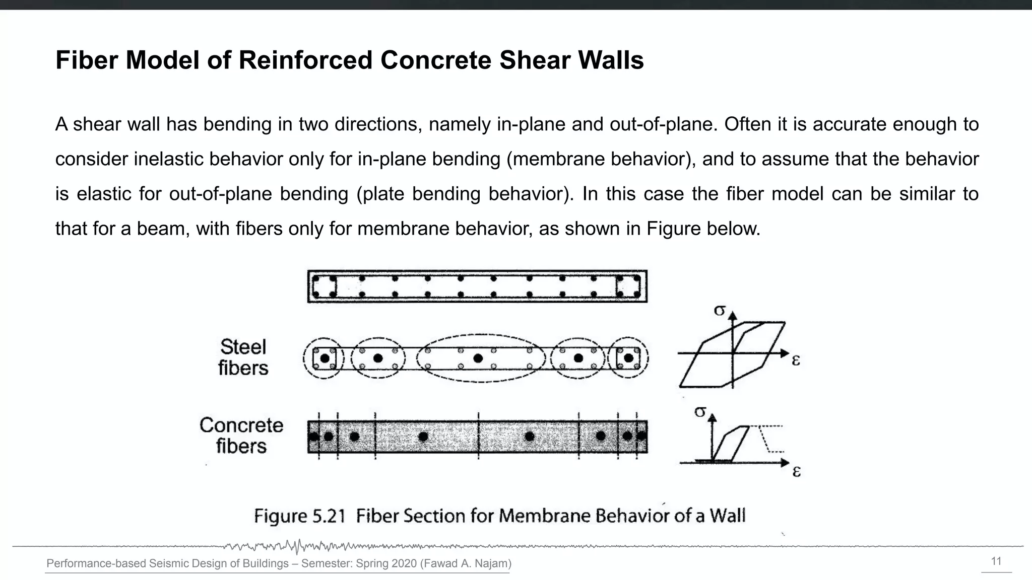
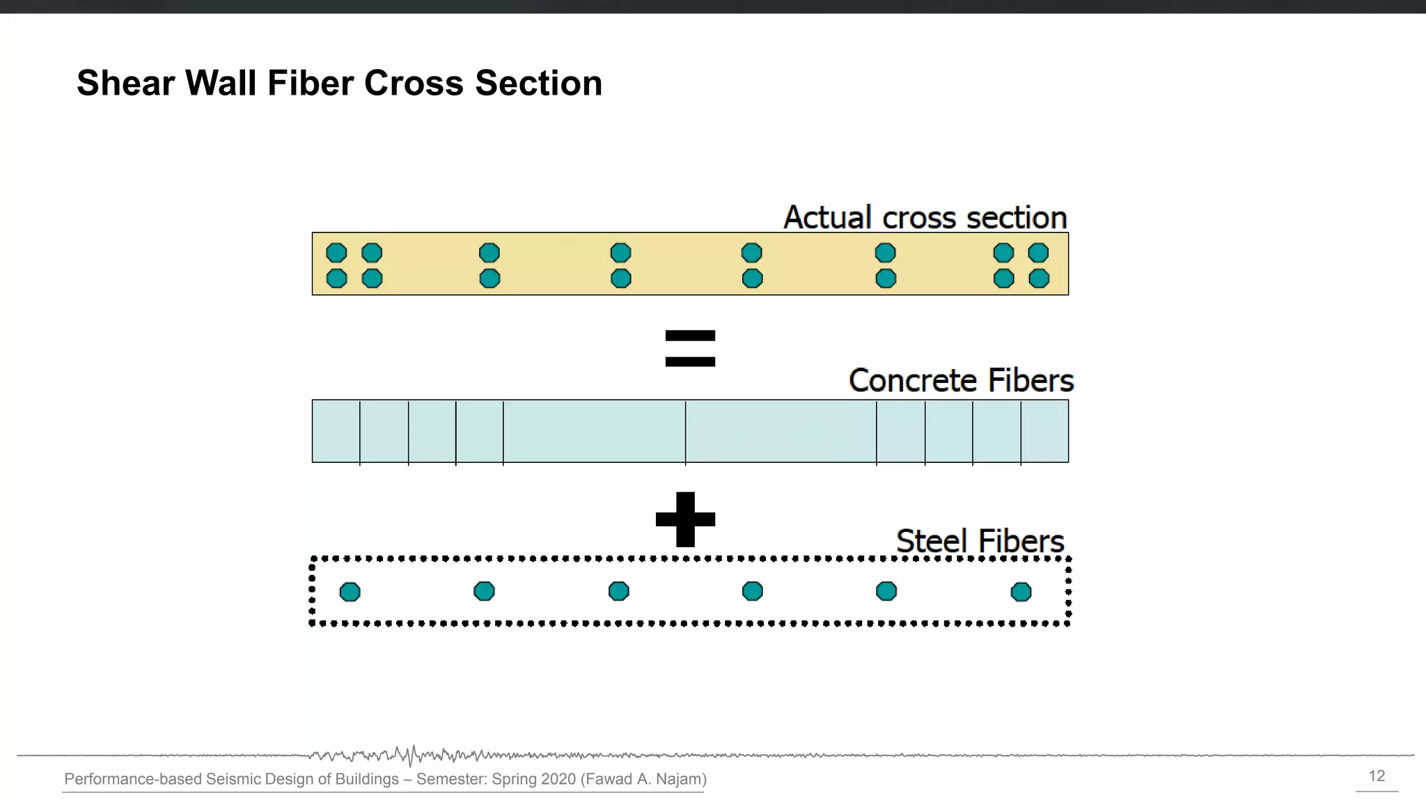
Fiber Model of Reinforced Concrete Shear Walls
A shear wall has bending in two directions, namely in-plane and out-of-plane. Often it is accurate enough to
consider inelastic behavior only for in-plane bending (membrane behavior), and to assume that the behavior
is elastic for out-of-plane bending (plate bending behavior). In this case the fiber model can be similar to
that for a beam, with fibers only for membrane behavior, as shown in Figure below.
13
Performance-based Seismic Designof Buildings – Semester: Spring 2020 (Fawad A. Najam)
Fiber Model of Reinforced Concrete Shear Walls
• As with a beam, an effective EI is specified for out-of-plane bending, and there is no coupling between
membrane and plate bending effects.
• If inelastic plate bending is to be considered, there must also be fibers through the wall thickness. In this
case the fiber model is similar to that for a column.
14.
14
Performance-based Seismic Designof Buildings – Semester: Spring 2020 (Fawad A. Najam)
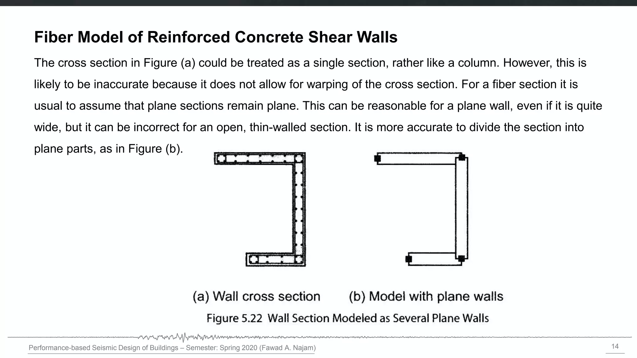
Fiber Model of Reinforced Concrete Shear Walls
The cross section in Figure (a) could be treated as a single section, rather like a column. However, this is
likely to be inaccurate because it does not allow for warping of the cross section. For a fiber section it is
usual to assume that plane sections remain plane. This can be reasonable for a plane wall, even if it is quite
wide, but it can be incorrect for an open, thin-walled section. It is more accurate to divide the section into
plane parts, as in Figure (b).
15.
15
Performance-based Seismic Designof Buildings – Semester: Spring 2020 (Fawad A. Najam)
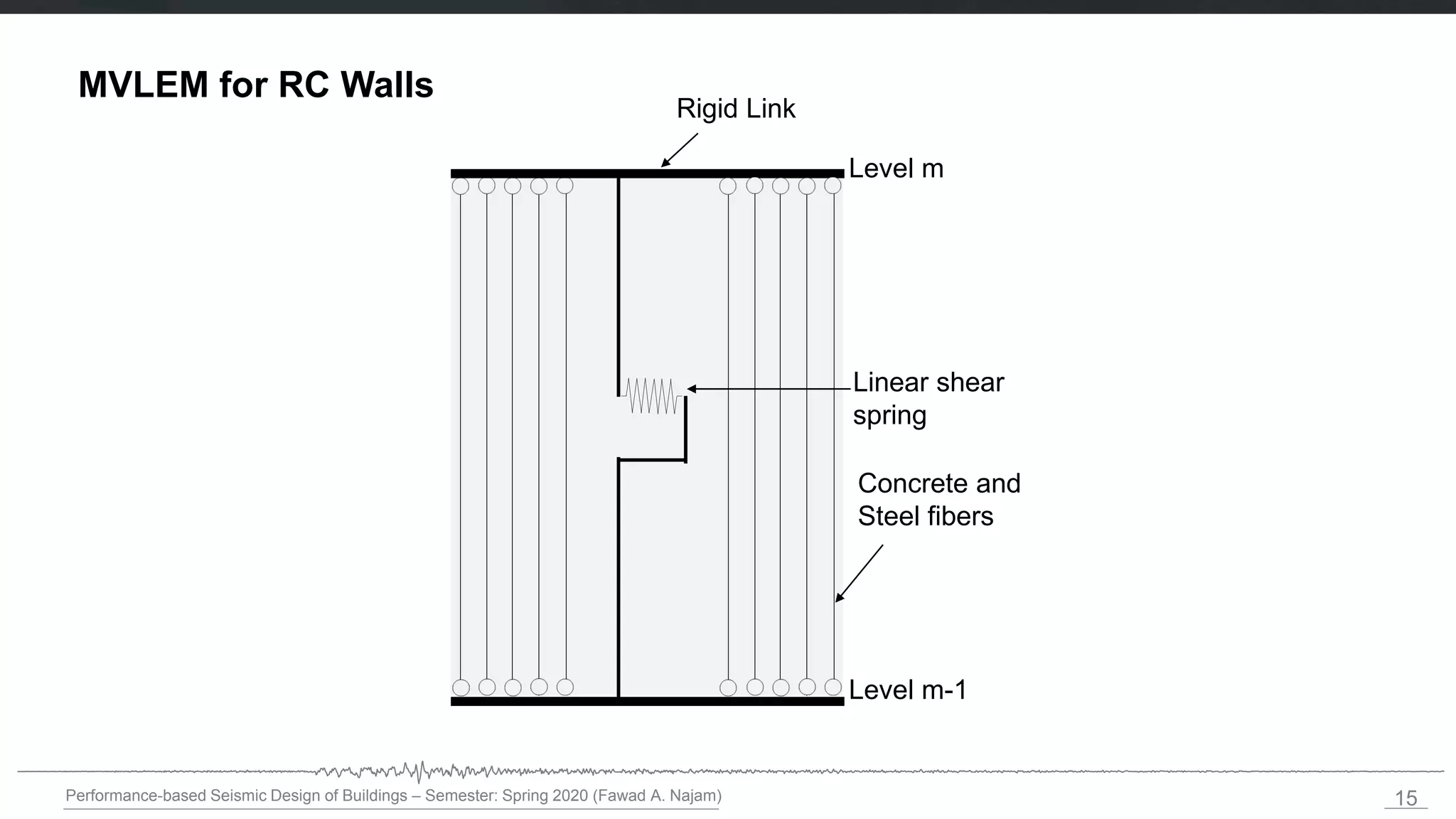
MVLEM for RC Walls
Level m
Level m-1
Rigid Link
Concrete and
Steel fibers
Linear shear
spring
16.
16
Performance-based Seismic Designof Buildings – Semester: Spring 2018 (Fawad A. Najam)
Nonlinear Modeling of Materials (for Fiber Modeling of Members)
17.
17
Performance-based Seismic Designof Buildings – Semester: Spring 2020 (Fawad A. Najam)
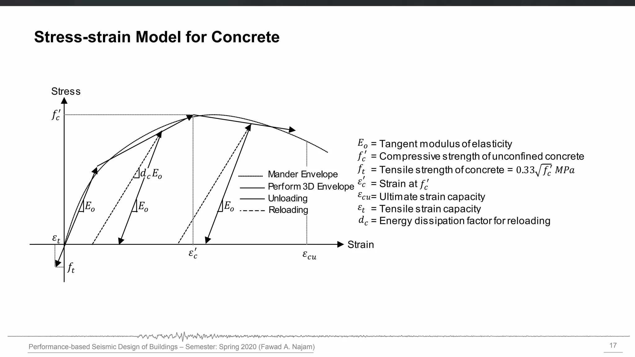
Stress-strain Model for Concrete
Stress
Strain
Mander Envelope
Perform 3D Envelope
Unloading
Reloading
Stress
= Tangent modulus ofelasticity
= Compressive strength ofunconfined concrete
= Tensile strength ofconcrete =
= Ultimate strain capacity
= Strain at
= Tensile strain capacity
= Energy dissipation factor for reloading
= Modulus of elasticity
18.
18
Performance-based Seismic Designof Buildings – Semester: Spring 2020 (Fawad A. Najam)
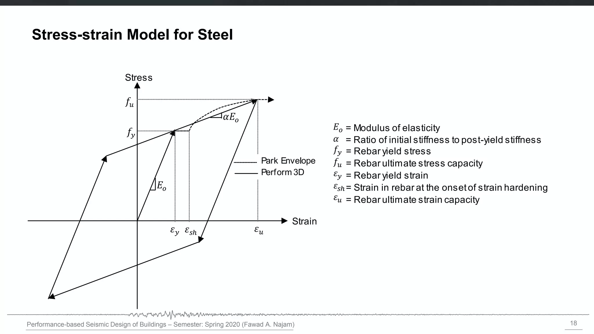
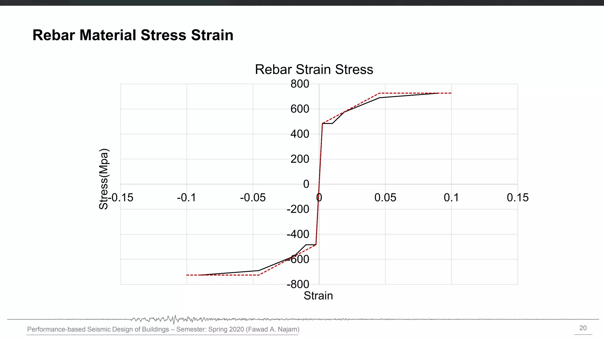
Stress-strain Model for Steel Strain
Reloading
Stress
Strain
= Energy dissipation factor for reloading
Park Envelope
Perform 3D
= Modulus of elasticity
= Rebar yield stress
= Rebar ultimate stress capacity
= Rebar ultimate strain capacity
= Rebar yield strain
= Strain in rebar at the onsetof strain hardening
= Ratio of initial stiffness to post-yield stiffness
19.
19
Performance-based Seismic Designof Buildings – Semester: Spring 2020 (Fawad A. Najam)
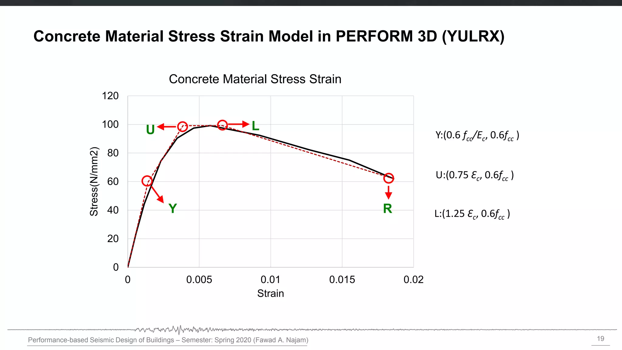
Concrete Material Stress Strain Model in PERFORM 3D (YULRX)
0
20
40
60
80
100
120
0 0.005 0.01 0.015 0.02
Stress(N/mm2)
Strain
Concrete Material Stress Strain
Y
U L
R
Y:(0.6 fcc/Ec, 0.6fcc )
U:(0.75 Ɛc, 0.6fcc )
L:(1.25 Ɛc, 0.6fcc )
21
Performance-based Seismic Designof Buildings – Semester: Spring 2020 (Fawad A. Najam)
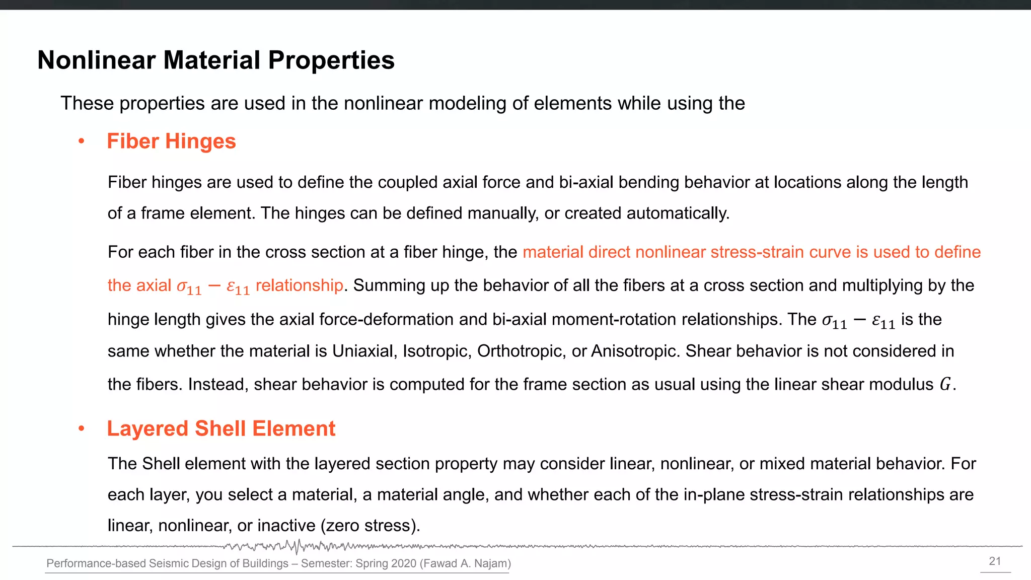
Nonlinear Material Properties
• Fiber Hinges
• Layered Shell Element
These properties are used in the nonlinear modeling of elements while using the
Fiber hinges are used to define the coupled axial force and bi-axial bending behavior at locations along the length
of a frame element. The hinges can be defined manually, or created automatically.
For each fiber in the cross section at a fiber hinge, the material direct nonlinear stress-strain curve is used to define
the axial 𝜎11 − 11 relationship. Summing up the behavior of all the fibers at a cross section and multiplying by the
hinge length gives the axial force-deformation and bi-axial moment-rotation relationships. The 𝜎11 − 11 is the
same whether the material is Uniaxial, Isotropic, Orthotropic, or Anisotropic. Shear behavior is not considered in
the fibers. Instead, shear behavior is computed for the frame section as usual using the linear shear modulus 𝐺.
The Shell element with the layered section property may consider linear, nonlinear, or mixed material behavior. For
each layer, you select a material, a material angle, and whether each of the in-plane stress-strain relationships are
linear, nonlinear, or inactive (zero stress).
22.
22
Performance-based Seismic Designof Buildings – Semester: Spring 2020 (Fawad A. Najam)
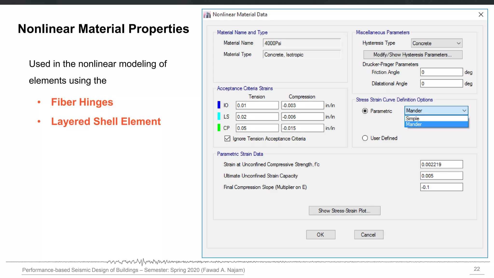
Nonlinear Material Properties
• Fiber Hinges
• Layered Shell Element
Used in the nonlinear modeling of
elements using the
23.
23
Performance-based Seismic Designof Buildings – Semester: Spring 2020 (Fawad A. Najam)
Acceptance Criteria
• Three points labeled IO, LS and CP are used to define the acceptance criteria for the hinge
• IO- Immediate Occupancy
• LS- Life Safety
• CP-Collapse Prevention
24.
24
Performance-based Seismic Designof Buildings – Semester: Spring 2020 (Fawad A. Najam)
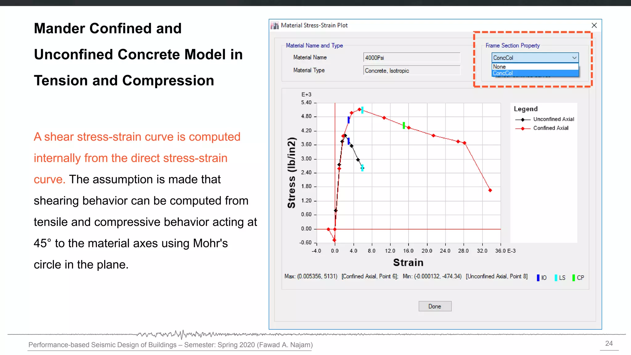
Mander Confined and
Unconfined Concrete Model in
Tension and Compression
A shear stress-strain curve is computed
internally from the direct stress-strain
curve. The assumption is made that
shearing behavior can be computed from
tensile and compressive behavior acting at
45° to the material axes using Mohr's
circle in the plane.
26
Performance-based Seismic Designof Buildings – Semester: Spring 2020 (Fawad A. Najam)
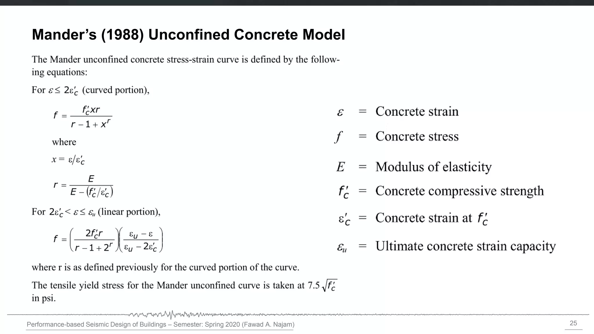
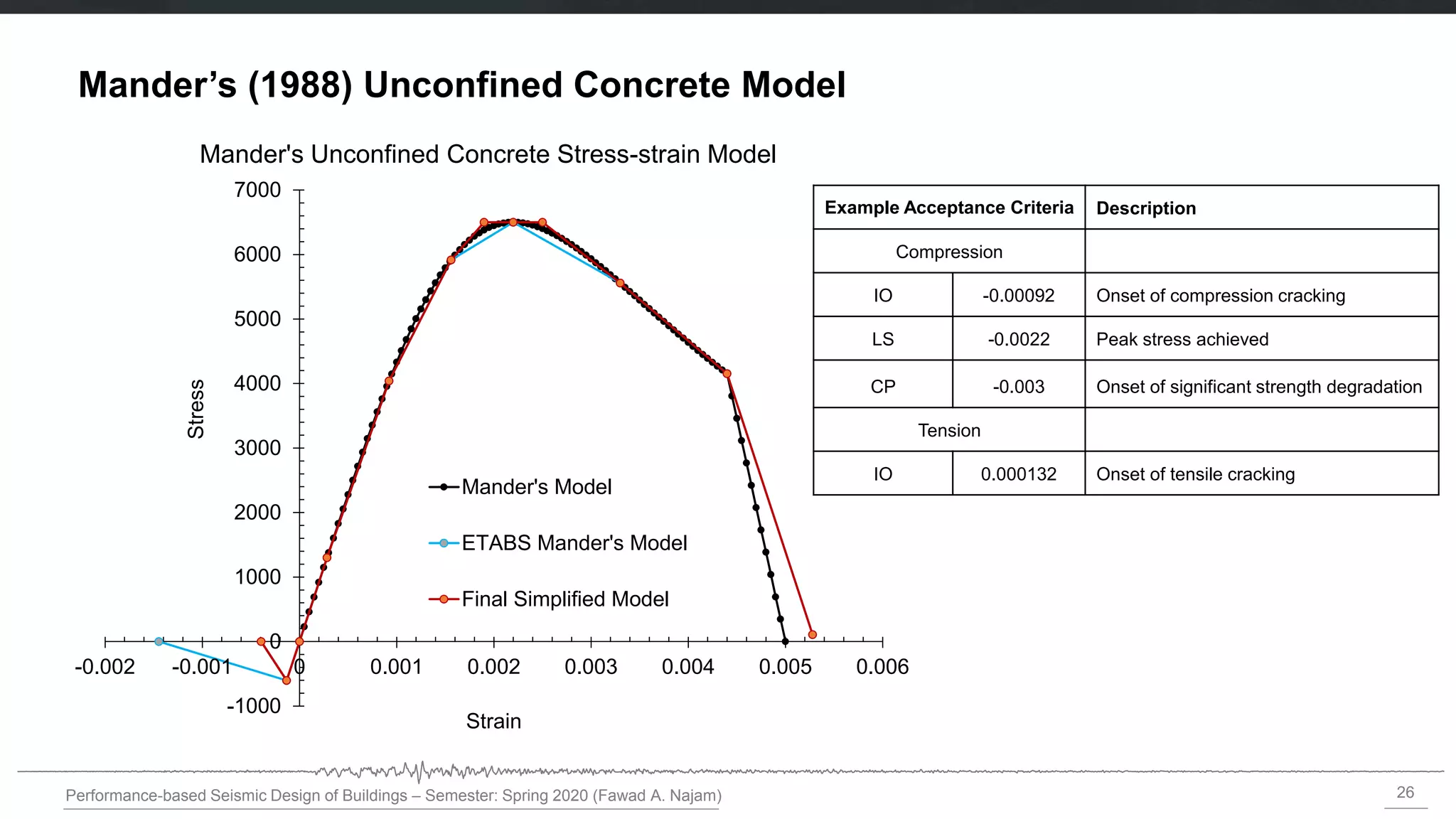
Mander’s (1988) Unconfined Concrete Model
-1000
0
1000
2000
3000
4000
5000
6000
7000
-0.002 -0.001 0 0.001 0.002 0.003 0.004 0.005 0.006
Stress
Strain
Mander's Unconfined Concrete Stress-strain Model
Mander's Model
ETABS Mander's Model
Final Simplified Model
Example Acceptance Criteria Description
Compression
IO -0.00092 Onset of compression cracking
LS -0.0022 Peak stress achieved
CP -0.003 Onset of significant strength degradation
Tension
IO 0.000132 Onset of tensile cracking
27.
27
Performance-based Seismic Designof Buildings – Semester: Spring 2020 (Fawad A. Najam)
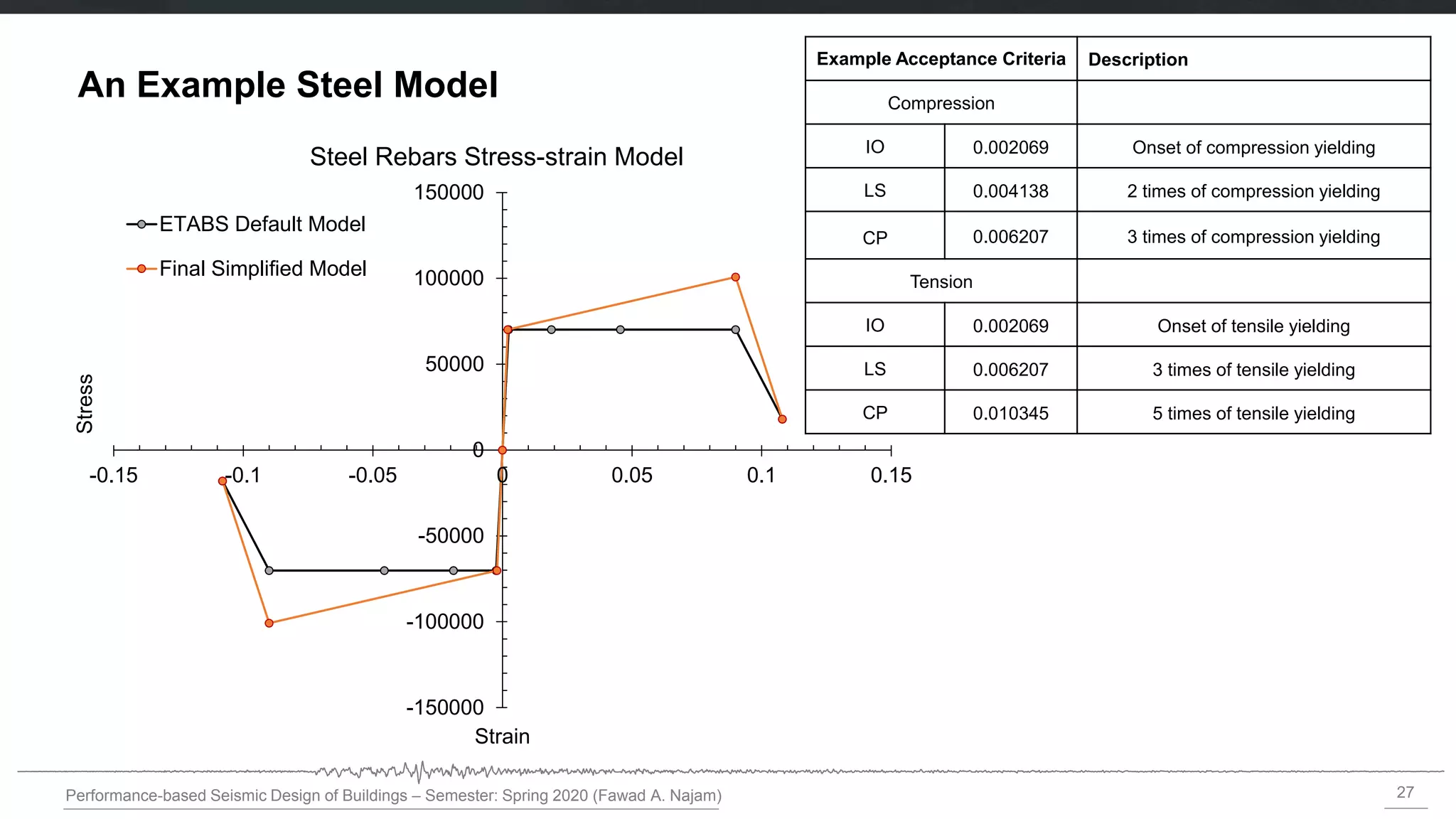
An Example Steel Model
-150000
-100000
-50000
0
50000
100000
150000
-0.15 -0.1 -0.05 0 0.05 0.1 0.15
Stress
Strain
Steel Rebars Stress-strain Model
ETABS Default Model
Final Simplified Model
Example Acceptance Criteria Description
Compression
IO 0.002069 Onset of compression yielding
LS 0.004138 2 times of compression yielding
CP 0.006207 3 times of compression yielding
Tension
IO 0.002069 Onset of tensile yielding
LS 0.006207 3 times of tensile yielding
CP 0.010345 5 times of tensile yielding
28.
28
Performance-based Seismic Designof Buildings – Semester: Spring 2020 (Fawad A. Najam)
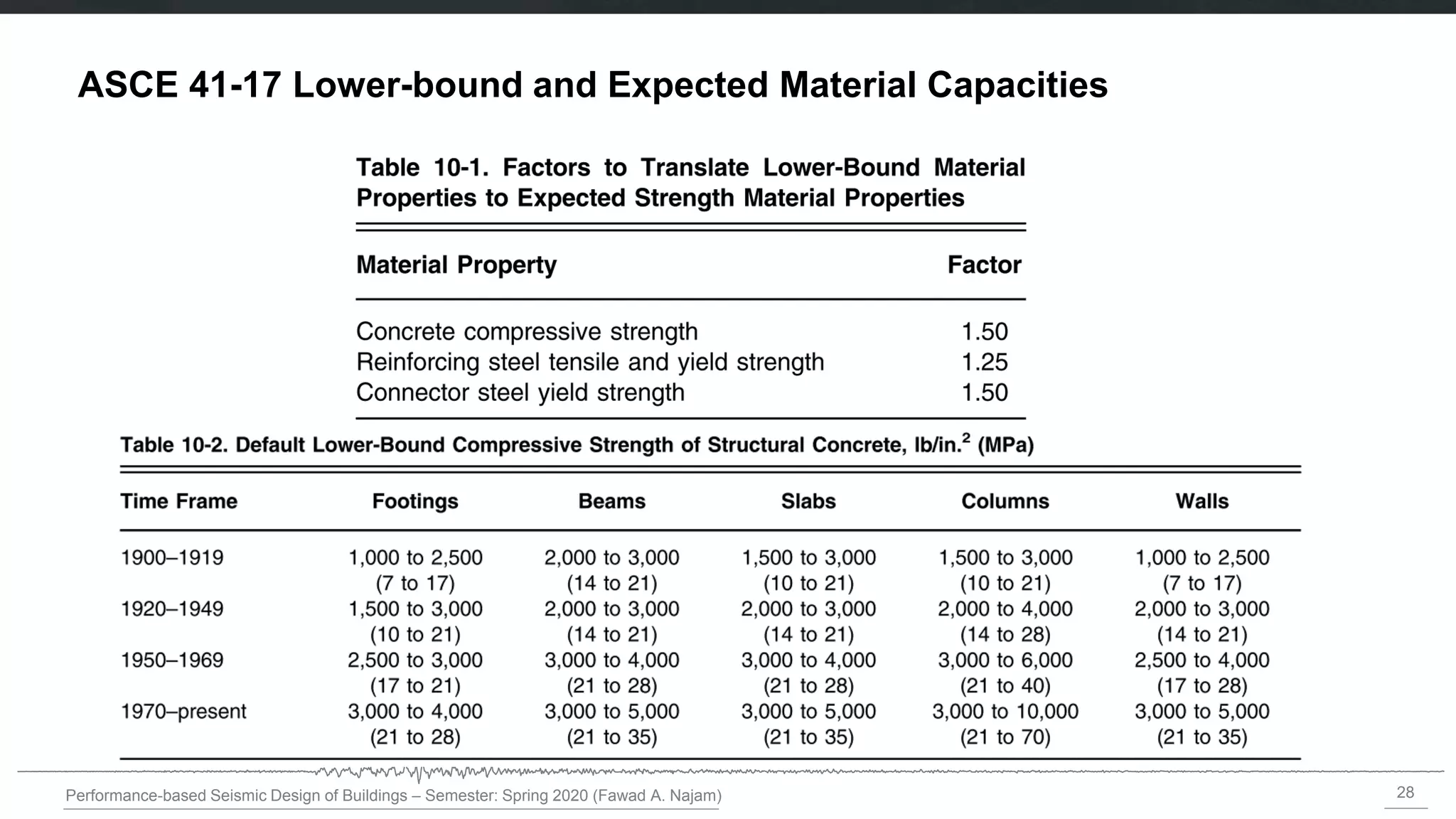
ASCE 41-17 Lower-bound and Expected Material Capacities
29.
29
Performance-based Seismic Designof Buildings – Semester: Spring 2020 (Fawad A. Najam)
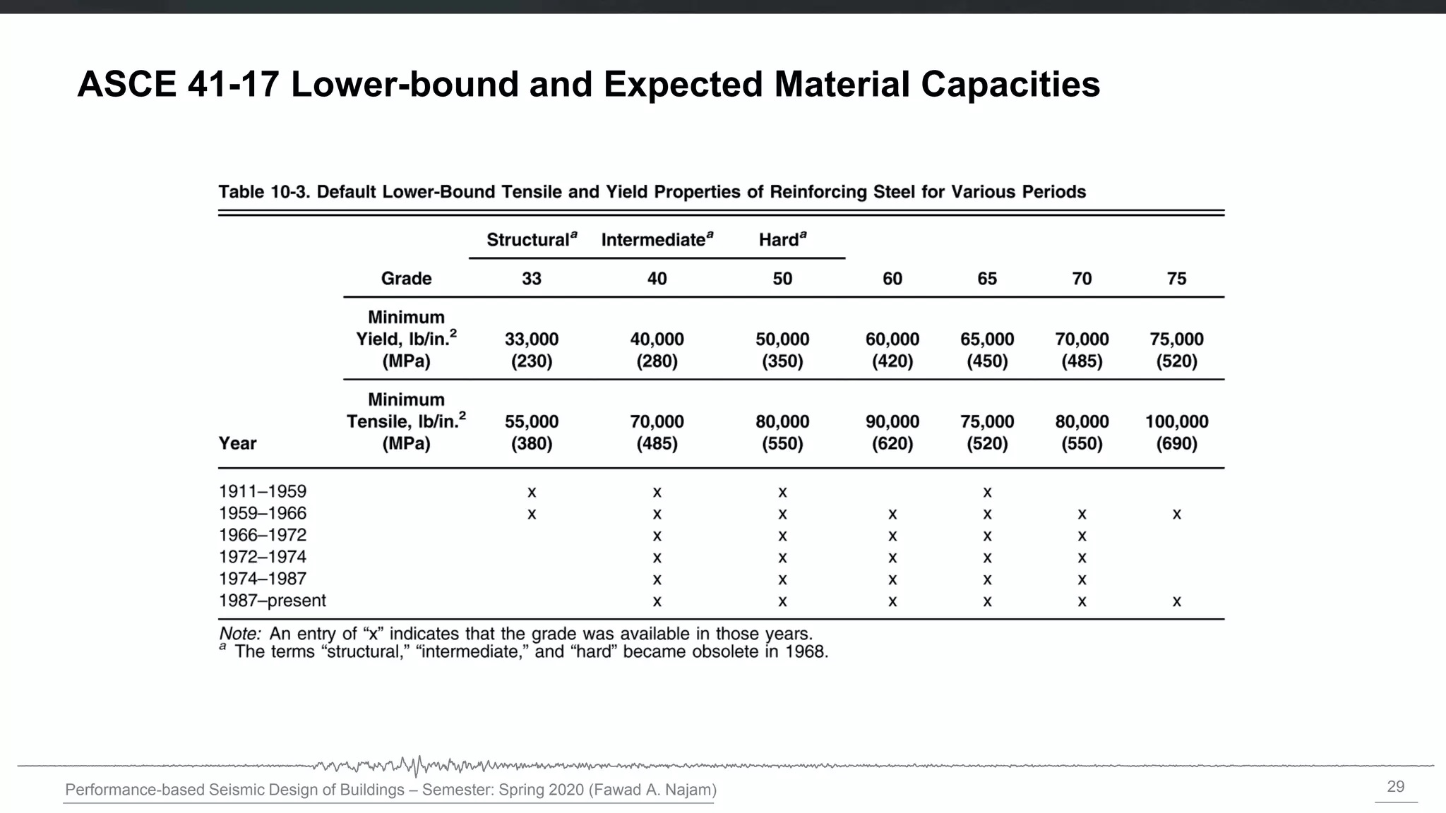
ASCE 41-17 Lower-bound and Expected Material Capacities
30.
30
Performance-based Seismic Designof Buildings – Semester: Spring 2018 (Fawad A. Najam)
Modeling of Hysteretic Behavior and Options Available in ETABS
31.
31
Performance-based Seismic Designof Buildings – Semester: Spring 2018 (Fawad A. Najam)
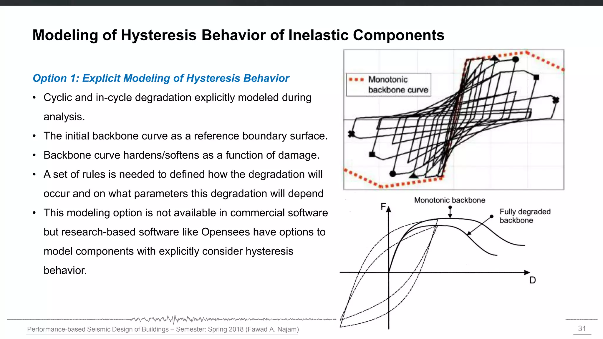
Option 1: Explicit Modeling of Hysteresis Behavior
• Cyclic and in-cycle degradation explicitly modeled during
analysis.
• The initial backbone curve as a reference boundary surface.
• Backbone curve hardens/softens as a function of damage.
• A set of rules is needed to defined how the degradation will
occur and on what parameters this degradation will depend
• This modeling option is not available in commercial software
but research-based software like Opensees have options to
model components with explicitly consider hysteresis
behavior.
Modeling of Hysteresis Behavior of Inelastic Components
32.
32
Performance-based Seismic Designof Buildings – Semester: Spring 2018 (Fawad A. Najam)
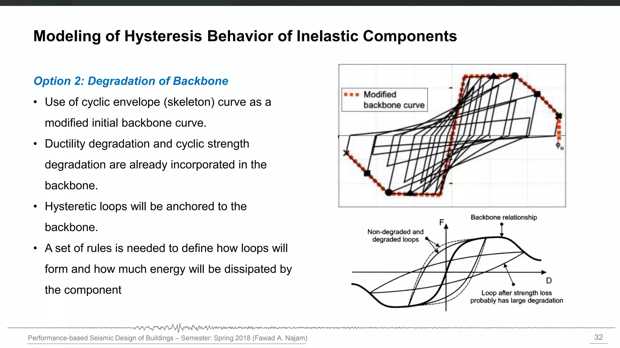
Option 2: Degradation of Backbone
• Use of cyclic envelope (skeleton) curve as a
modified initial backbone curve.
• Ductility degradation and cyclic strength
degradation are already incorporated in the
backbone.
• Hysteretic loops will be anchored to the
backbone.
• A set of rules is needed to define how loops will
form and how much energy will be dissipated by
the component
Modeling of Hysteresis Behavior of Inelastic Components
33.
33
Performance-based Seismic Designof Buildings – Semester: Spring 2018 (Fawad A. Najam)
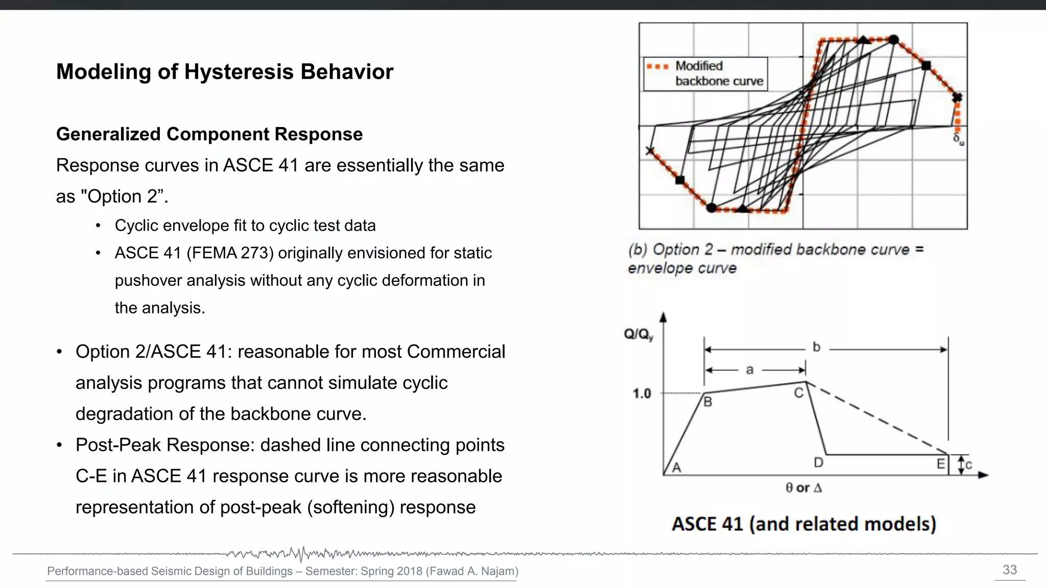
Generalized Component Response
Response curves in ASCE 41 are essentially the same
as "Option 2”.
• Cyclic envelope fit to cyclic test data
• ASCE 41 (FEMA 273) originally envisioned for static
pushover analysis without any cyclic deformation in
the analysis.
• Option 2/ASCE 41: reasonable for most Commercial
analysis programs that cannot simulate cyclic
degradation of the backbone curve.
• Post-Peak Response: dashed line connecting points
C-E in ASCE 41 response curve is more reasonable
representation of post-peak (softening) response
Modeling of Hysteresis Behavior
35
Performance-based Seismic Designof Buildings – Semester: Spring 2020 (Fawad A. Najam)
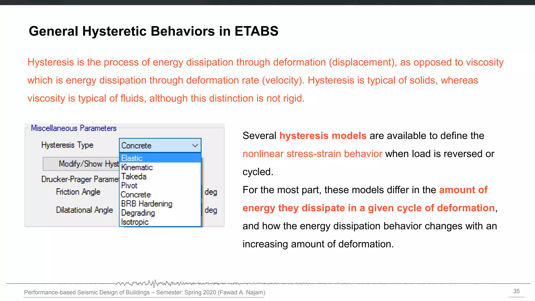
General Hysteretic Behaviors in ETABS
Several hysteresis models are available to define the
nonlinear stress-strain behavior when load is reversed or
cycled.
For the most part, these models differ in the amount of
energy they dissipate in a given cycle of deformation,
and how the energy dissipation behavior changes with an
increasing amount of deformation.
Hysteresis is the process of energy dissipation through deformation (displacement), as opposed to viscosity
which is energy dissipation through deformation rate (velocity). Hysteresis is typical of solids, whereas
viscosity is typical of fluids, although this distinction is not rigid.
36.
36
Performance-based Seismic Designof Buildings – Semester: Spring 2020 (Fawad A. Najam)
Hysteretic Models
Each hysteresis model may be used for the following purposes:
• Material stress-strain behavior, affecting frame fiber hinges and layered shells that use the
material
• Single degree-of-freedom frame hinges, such as M3 or P hinges. Interacting hinges, such as P-M3
or P-M2-M3, currently use the isotropic model
• Link/support elements of type multi-linear plasticity.
37.
37
Performance-based Seismic Designof Buildings – Semester: Spring 2020 (Fawad A. Najam)
Backbone Curve (Action vs. Deformation)
• For each material, hinge, or link degree of freedom, a uniaxial action vs. deformation curve defines
the non-linear behavior under monotonic loading in the positive and negative directions.
• Here action and deformation are an energy conjugate pair as follows:
• For materials, stress vs. strain
• For hinges and multi-linear links, force vs. deformation or moment vs. rotation, depending upon the
degree of freedom to which it is applied
• For each model, the uniaxial action-deformation curve is given by a set of points that you define. This
curve is called the backbone curve.
38.
38
Performance-based Seismic Designof Buildings – Semester: Spring 2020 (Fawad A. Najam)
Elastic Hysteresis Model
The behavior is nonlinear but also elastic. This means that the material always loads and unloads along
the backbone curve, and no energy is dissipated.
39.
39
Performance-based Seismic Designof Buildings – Semester: Spring 2020 (Fawad A. Najam)
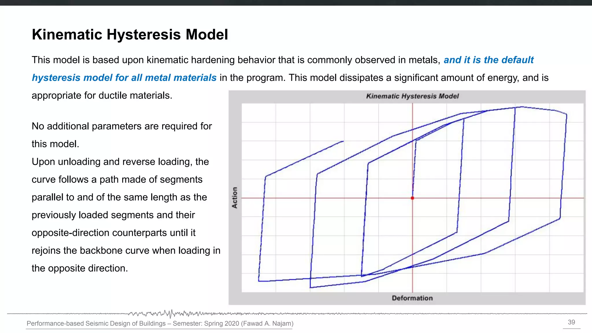
Kinematic Hysteresis Model
This model is based upon kinematic hardening behavior that is commonly observed in metals, and it is the default
hysteresis model for all metal materials in the program. This model dissipates a significant amount of energy, and is
appropriate for ductile materials.
No additional parameters are required for
this model.
Upon unloading and reverse loading, the
curve follows a path made of segments
parallel to and of the same length as the
previously loaded segments and their
opposite-direction counterparts until it
rejoins the backbone curve when loading in
the opposite direction.
40.
40
Performance-based Seismic Designof Buildings – Semester: Spring 2020 (Fawad A. Najam)
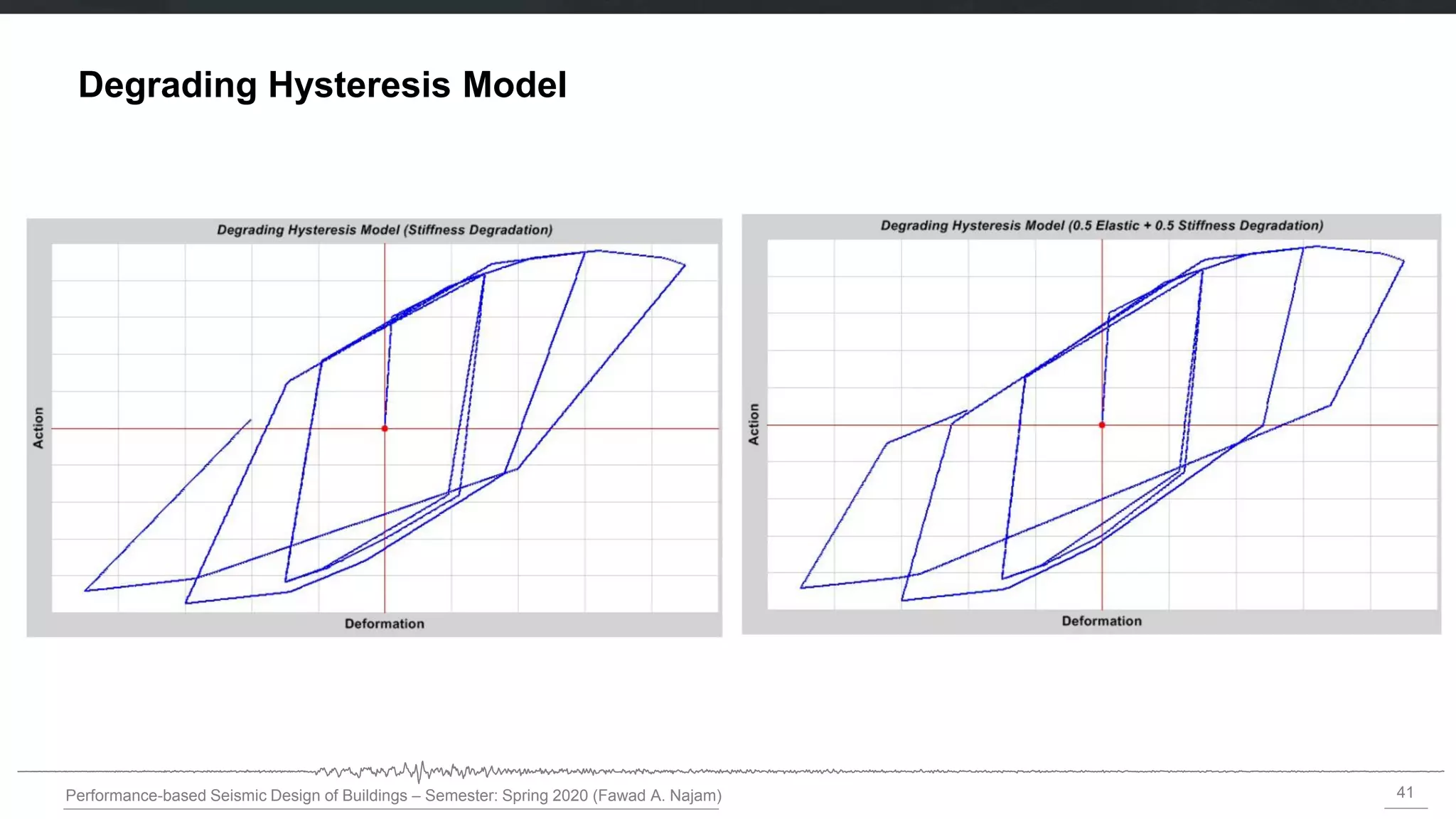
Degrading Hysteresis Model
This model is very similar to the Kinematic model, but uses a degrading hysteretic loop that accounts for
decreasing energy dissipation and unloading stiffness with increasing plastic deformation.
42
Performance-based Seismic Designof Buildings – Semester: Spring 2020 (Fawad A. Najam)
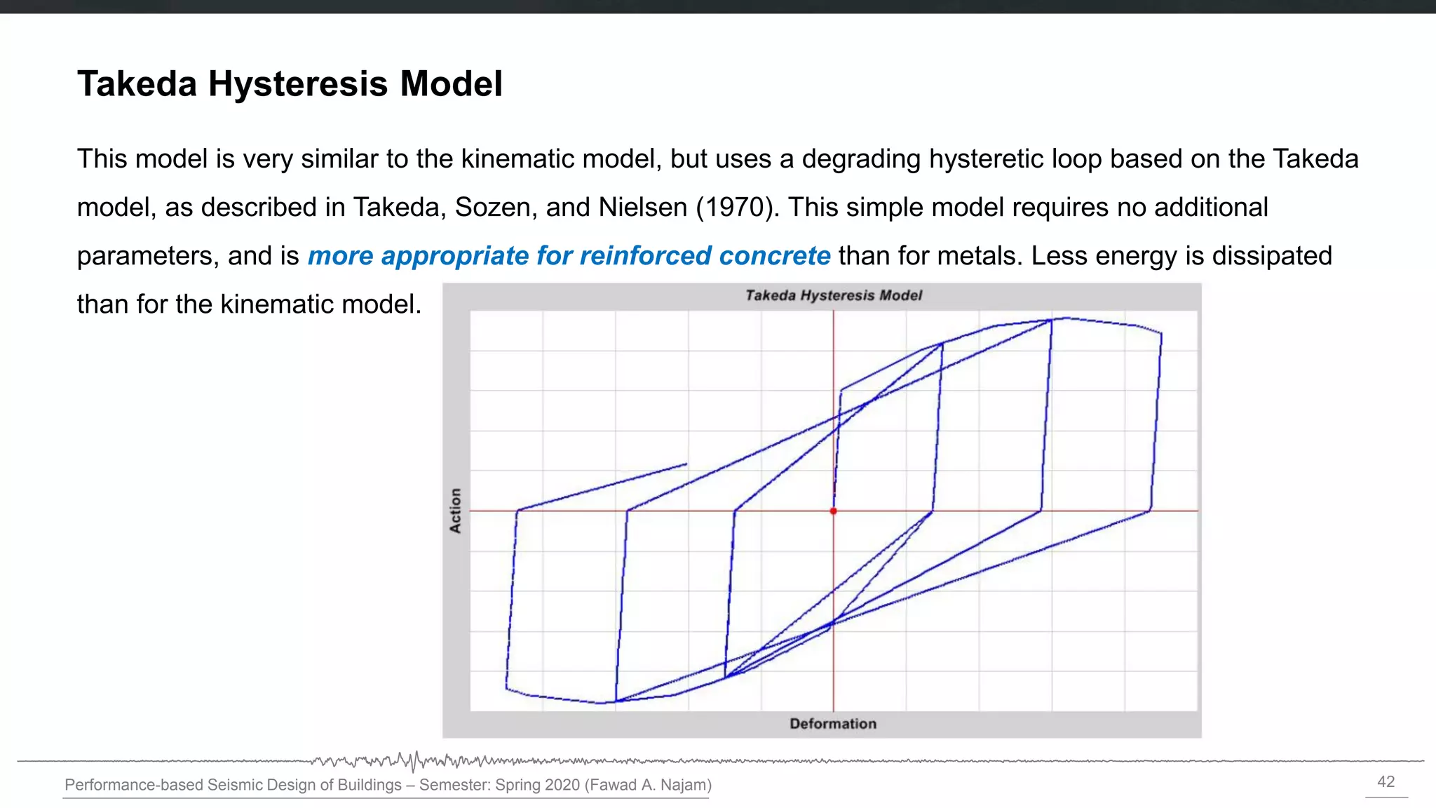
Takeda Hysteresis Model
This model is very similar to the kinematic model, but uses a degrading hysteretic loop based on the Takeda
model, as described in Takeda, Sozen, and Nielsen (1970). This simple model requires no additional
parameters, and is more appropriate for reinforced concrete than for metals. Less energy is dissipated
than for the kinematic model.
43.
43
Performance-based Seismic Designof Buildings – Semester: Spring 2020 (Fawad A. Najam)
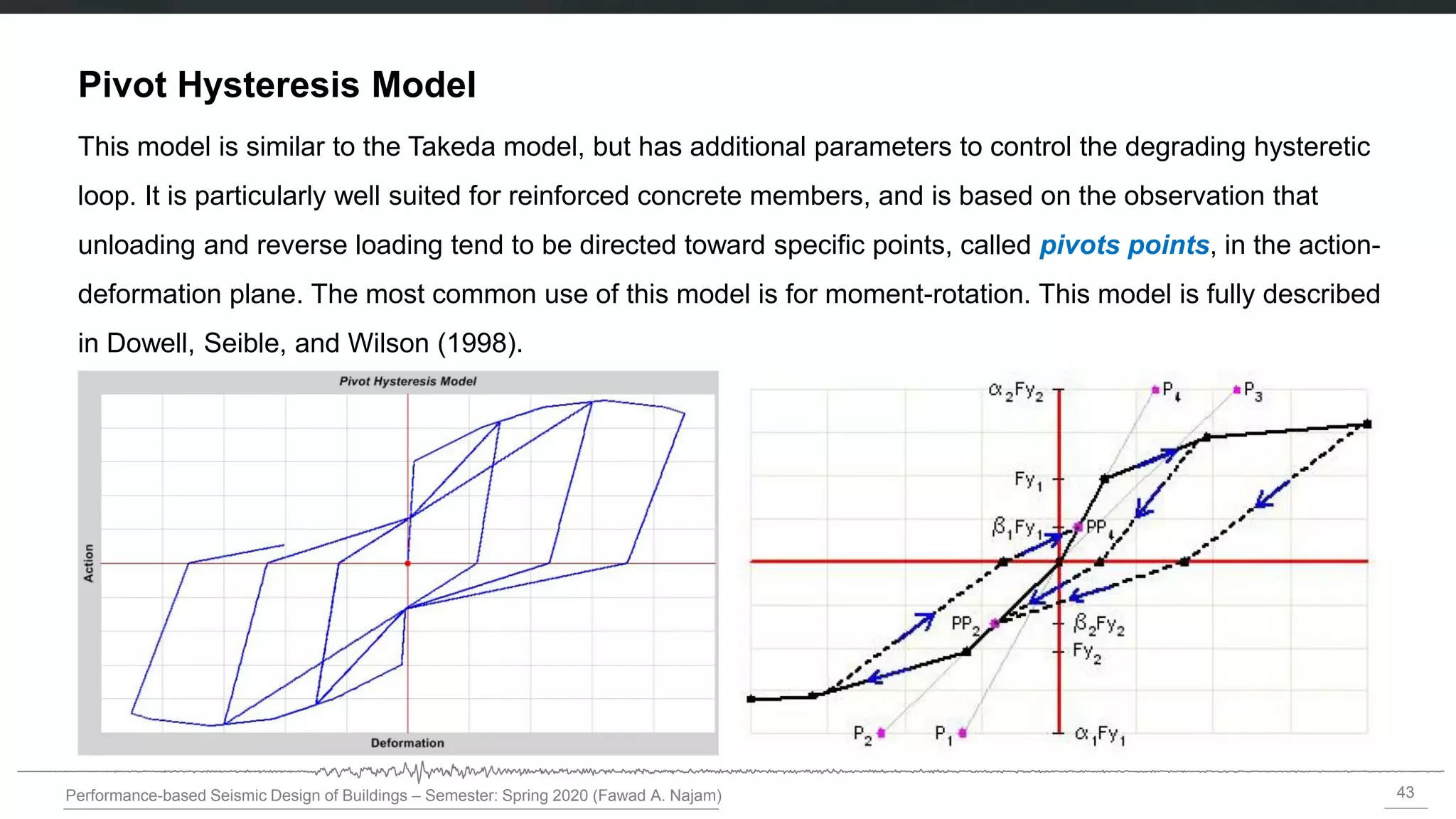
Pivot Hysteresis Model
This model is similar to the Takeda model, but has additional parameters to control the degrading hysteretic
loop. It is particularly well suited for reinforced concrete members, and is based on the observation that
unloading and reverse loading tend to be directed toward specific points, called pivots points, in the action-
deformation plane. The most common use of this model is for moment-rotation. This model is fully described
in Dowell, Seible, and Wilson (1998).
44.
44
Performance-based Seismic Designof Buildings – Semester: Spring 2020 (Fawad A. Najam)
Concrete Hysteresis Model
This model is intended for unreinforced concrete and similar materials, and is the default model for
concrete and masonry materials in the program. Tension and compression behavior are independent and
behave differently.
45.
45
Performance-based Seismic Designof Buildings – Semester: Spring 2020 (Fawad A. Najam)
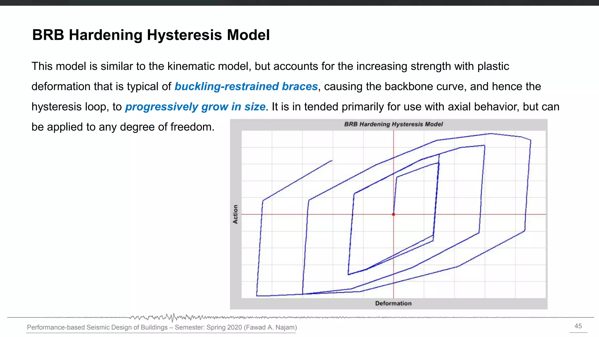
BRB Hardening Hysteresis Model
This model is similar to the kinematic model, but accounts for the increasing strength with plastic
deformation that is typical of buckling-restrained braces, causing the backbone curve, and hence the
hysteresis loop, to progressively grow in size. It is in tended primarily for use with axial behavior, but can
be applied to any degree of freedom.
46.
46
Performance-based Seismic Designof Buildings – Semester: Spring 2020 (Fawad A. Najam)
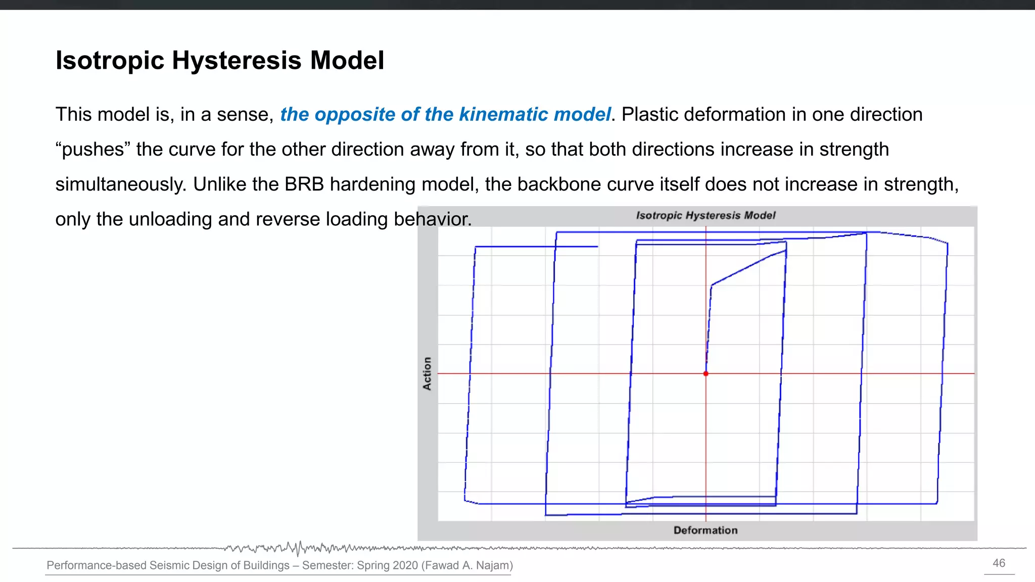
Isotropic Hysteresis Model
This model is, in a sense, the opposite of the kinematic model. Plastic deformation in one direction
“pushes” the curve for the other direction away from it, so that both directions increase in strength
simultaneously. Unlike the BRB hardening model, the backbone curve itself does not increase in strength,
only the unloading and reverse loading behavior.
47.
47
Performance-based Seismic Designof Buildings – Semester: Spring 2020 (Fawad A. Najam)
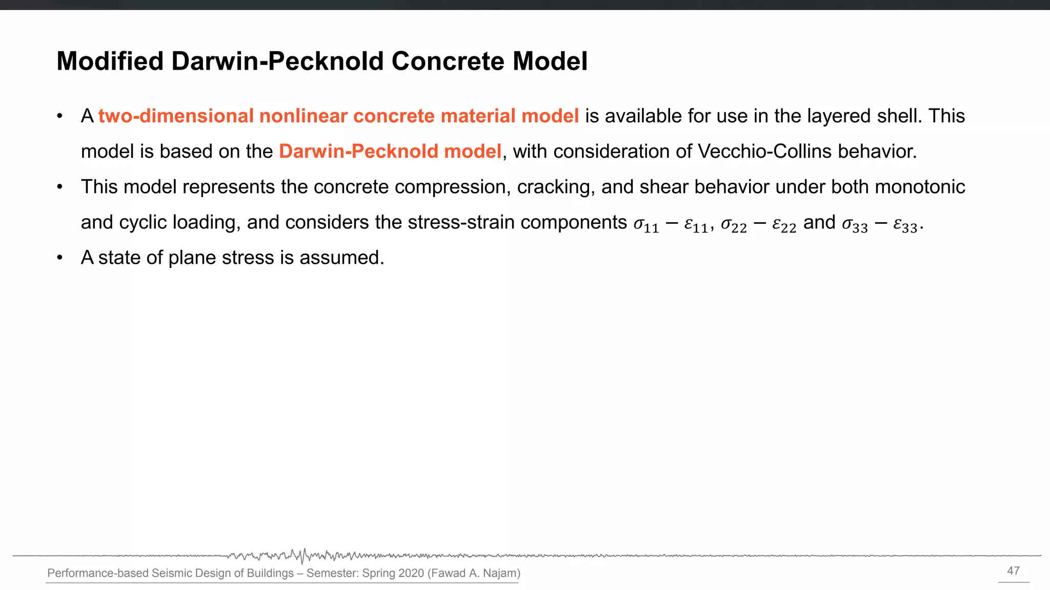
Modified Darwin-Pecknold Concrete Model
• A two-dimensional nonlinear concrete material model is available for use in the layered shell. This
model is based on the Darwin-Pecknold model, with consideration of Vecchio-Collins behavior.
• This model represents the concrete compression, cracking, and shear behavior under both monotonic
and cyclic loading, and considers the stress-strain components 𝜎11 − 11, 𝜎22 − 22 and 𝜎33 − 33.
• A state of plane stress is assumed.
48.
48
Performance-based Seismic Designof Buildings – Semester: Spring 2020 (Fawad A. Najam)
ETABS Demonstration on
Nonlinear Modeling of Materials
(Fibers)
50
Performance-based Seismic Designof Buildings – Semester: Spring 2020 (Fawad A. Najam)
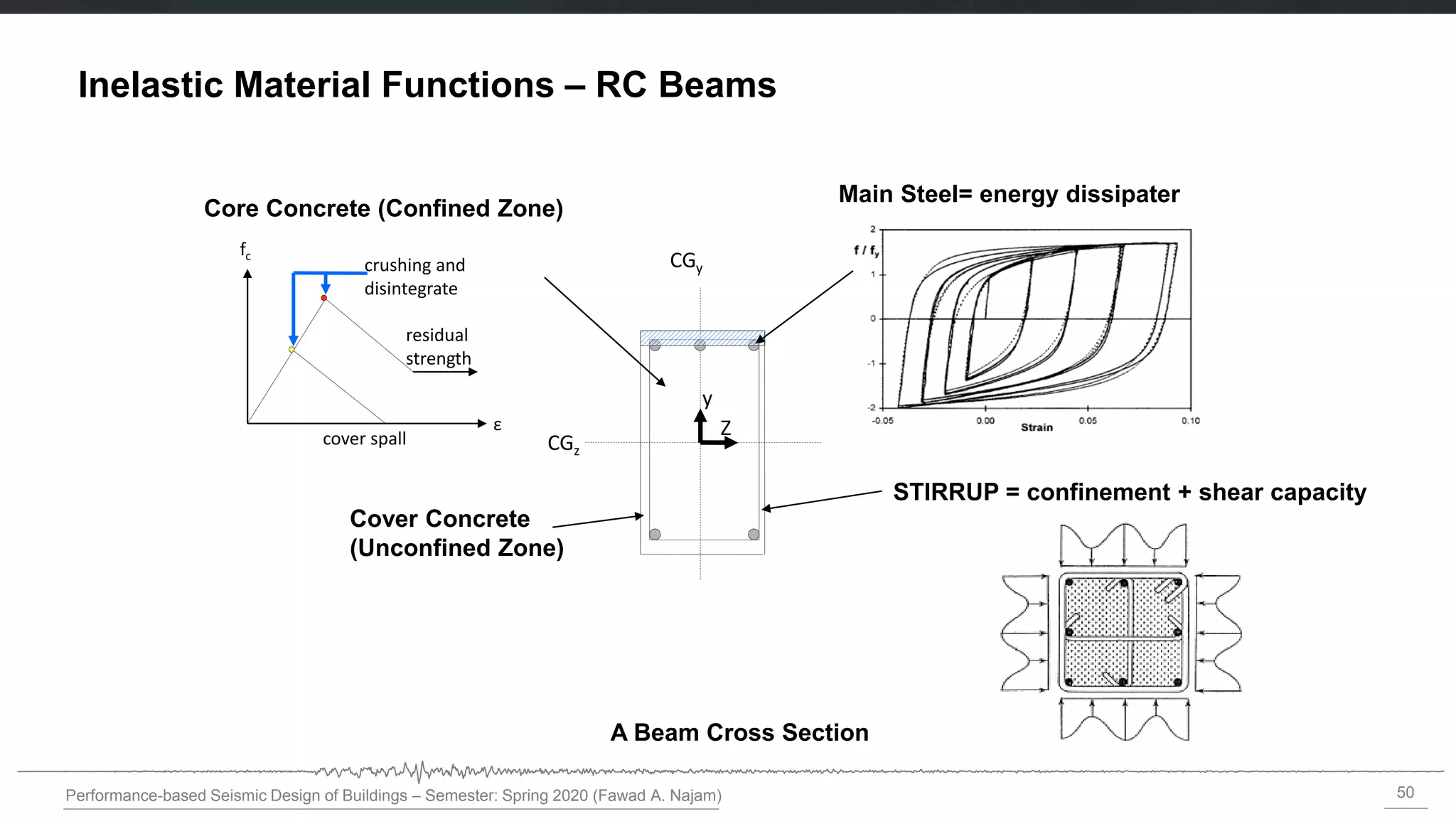
Inelastic Material Functions – RC Beams
CGz
CGy
Z
y
A Beam Cross Section
Main Steel= energy dissipater
Core Concrete (Confined Zone)
Cover Concrete
(Unconfined Zone)
cover spall
crushing and
disintegrate
ε
fc
residual
strength
STIRRUP = confinement + shear capacity
51.
51
Performance-based Seismic Designof Buildings – Semester: Spring 2020 (Fawad A. Najam)
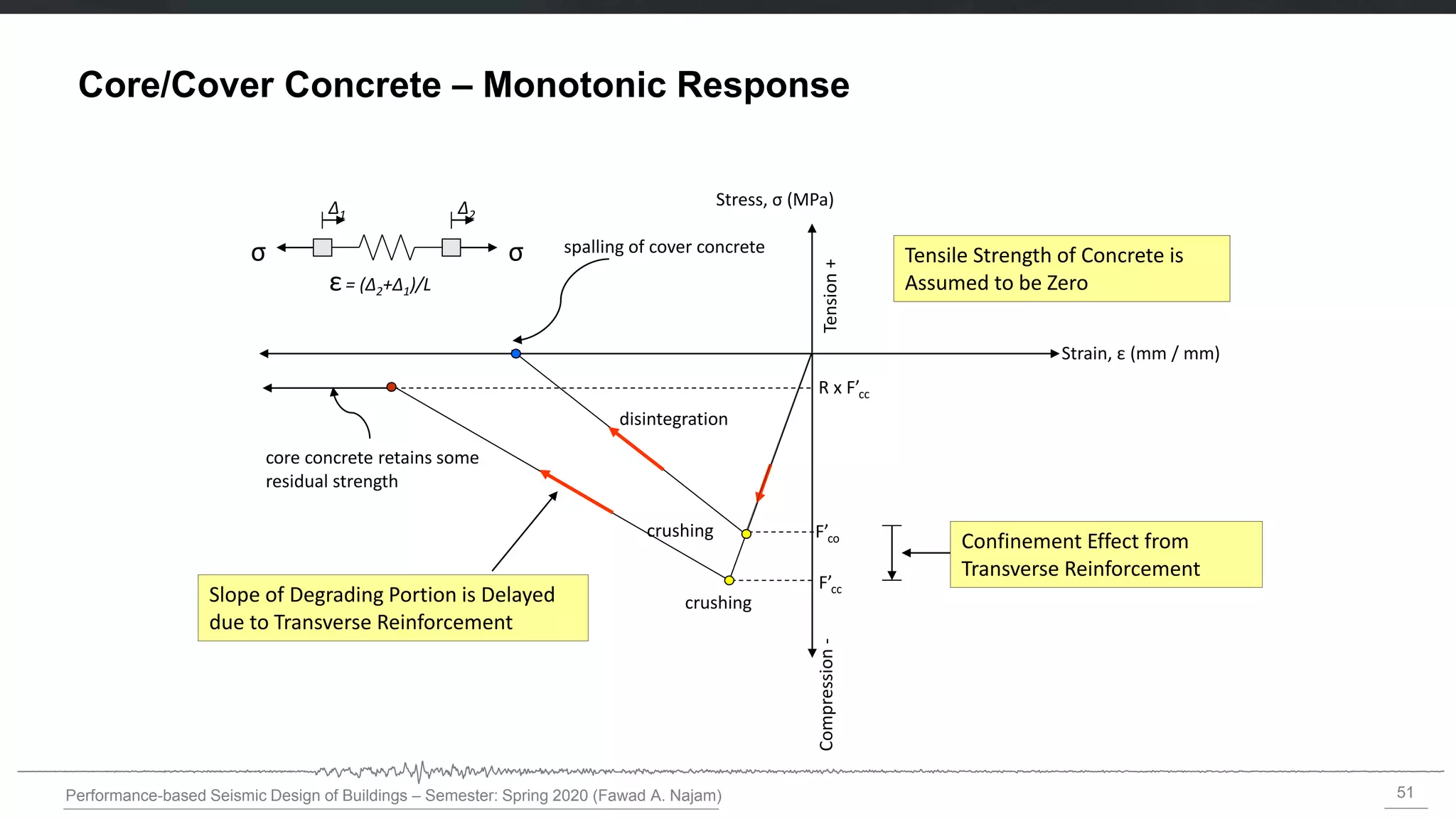
Core/Cover Concrete – Monotonic Response
Stress, σ (MPa)
Tension
+
Compression
-
crushing
Strain, ε (mm / mm)
spalling of cover concrete
core concrete retains some
residual strength
F’cc
R x F’cc
Tensile Strength of Concrete is
Assumed to be Zero
F’co Confinement Effect from
Transverse Reinforcement
Slope of Degrading Portion is Delayed
due to Transverse Reinforcement
σ
σ
Δ1 Δ2
ε= (Δ2+Δ1)/L
disintegration
crushing
52.
52
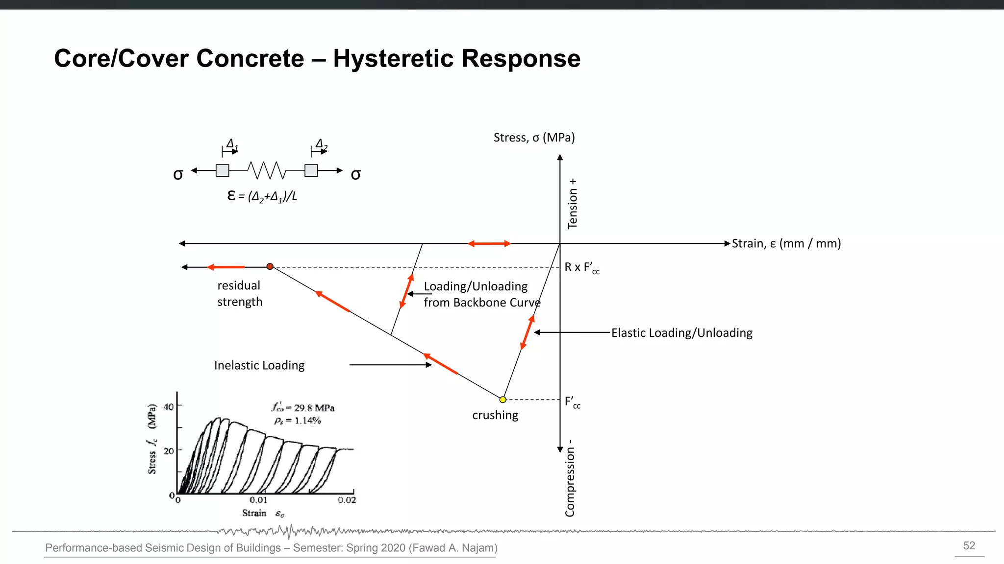
Performance-based Seismic Designof Buildings – Semester: Spring 2020 (Fawad A. Najam)
Stress, σ (MPa)
Tension
+
Compression
-
crushing
Strain, ε (mm / mm)
F’cc
R x F’cc
σ
σ
Δ1 Δ2
ε= (Δ2+Δ1)/L
residual
strength
Elastic Loading/Unloading
Inelastic Loading
Loading/Unloading
from Backbone Curve
Core/Cover Concrete – Hysteretic Response
53.
53
Performance-based Seismic Designof Buildings – Semester: Spring 2020 (Fawad A. Najam)
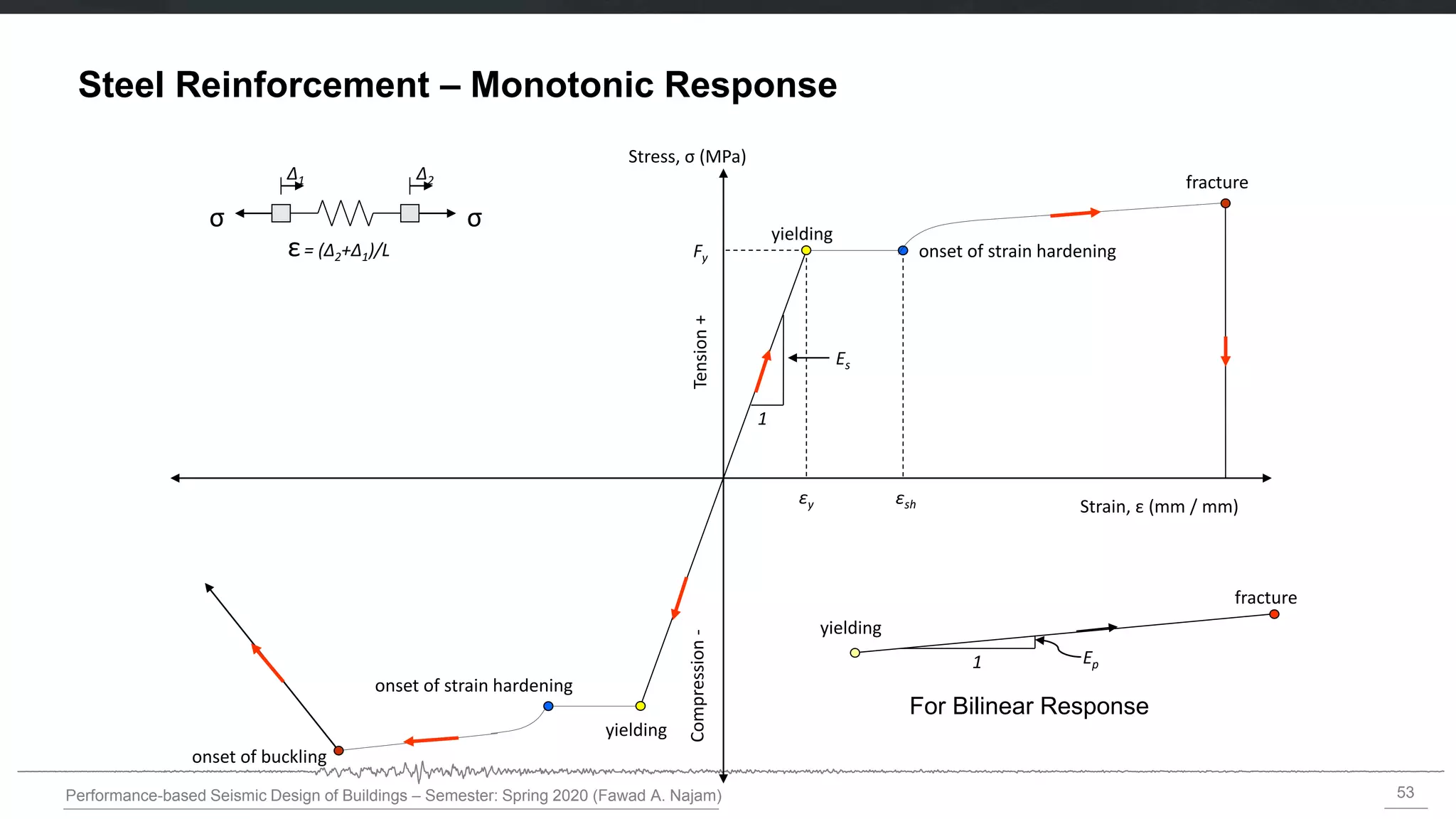
Steel Reinforcement – Monotonic Response
Tension
+
Compression
-
yielding
Stress, σ (MPa)
Strain, ε (mm / mm)
σ
σ
Δ1 Δ2
ε= (Δ2+Δ1)/L
εsh
onset of strain hardening
Ep
1
fracture
yielding
onset of strain hardening
fracture
onset of buckling
Fy
1
Es
εy
yielding
For Bilinear Response
54.
54
Performance-based Seismic Designof Buildings – Semester: Spring 2020 (Fawad A. Najam)
Steel Reinforcement – Hysteretic Response
Hysteretic response of reinforcing steel
[L.L. Dodd and J.I. Restrepo-Posada, 1995]
EPP-Model Bilinear Model (Clough) Ramberg-Osgood Model
55.
55
Performance-based Seismic Designof Buildings – Semester: Spring 2020 (Fawad A. Najam)
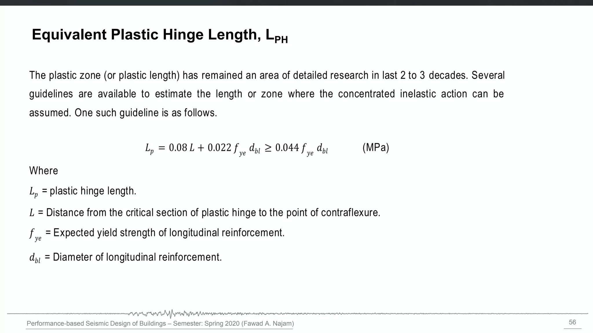
Equivalent Plastic Hinge Length, LPH
max
( )
PH PH
PH length
x dx L
Empirical equations for Lph can be found in the literature
Concept of “Equivalent Plastic Hinge Length, LPH”
0.08 0.022
PH b y
L L d F
[Paulay and Priestley, 1992]
57
Performance-based Seismic Designof Buildings – Semester: Spring 2020 (Fawad A. Najam)
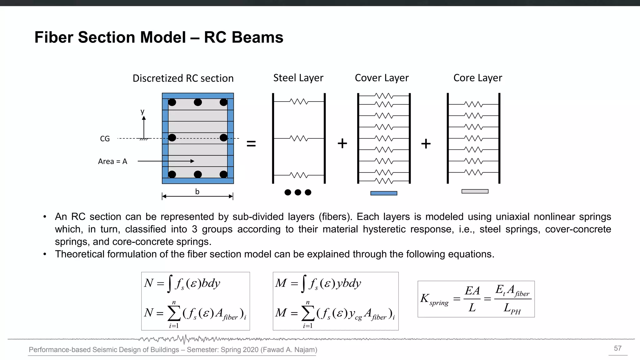
Fiber Section Model – RC Beams
• An RC section can be represented by sub-divided layers (fibers). Each layers is modeled using uniaxial nonlinear springs
which, in turn, classified into 3 groups according to their material hysteretic response, i.e., steel springs, cover-concrete
springs, and core-concrete springs.
• Theoretical formulation of the fiber section model can be explained through the following equations.
Discretized RC section Steel Layer Cover Layer Core Layer
+ +
=
1
( )
( ( ) )
s
n
s cg fiber i
i
M f ybdy
M f y A
1
( )
( ( ) )
s
n
s fiber i
i
N f bdy
N f A
b
CG
y
Area = A
t fiber
spring
PH
E A
EA
K
L L
= =
58.
58
Performance-based Seismic Designof Buildings – Semester: Spring 2020 (Fawad A. Najam)
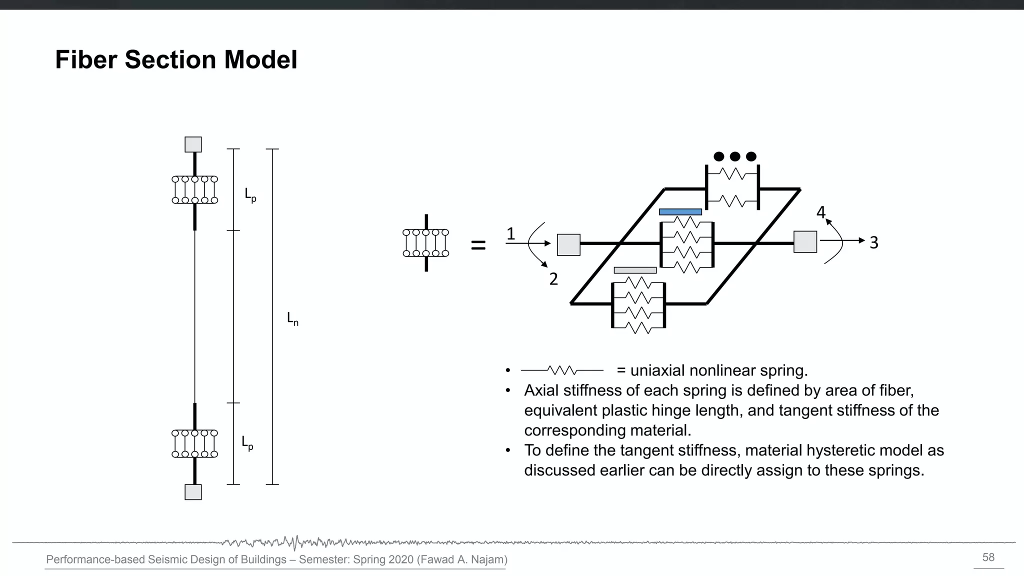
Fiber Section Model
• = uniaxial nonlinear spring.
• Axial stiffness of each spring is defined by area of fiber,
equivalent plastic hinge length, and tangent stiffness of the
corresponding material.
• To define the tangent stiffness, material hysteretic model as
discussed earlier can be directly assign to these springs.
1
2
3
4
=
Lp
Lp
Ln
59.
59
Performance-based Seismic Designof Buildings – Semester: Spring 2020 (Fawad A. Najam)
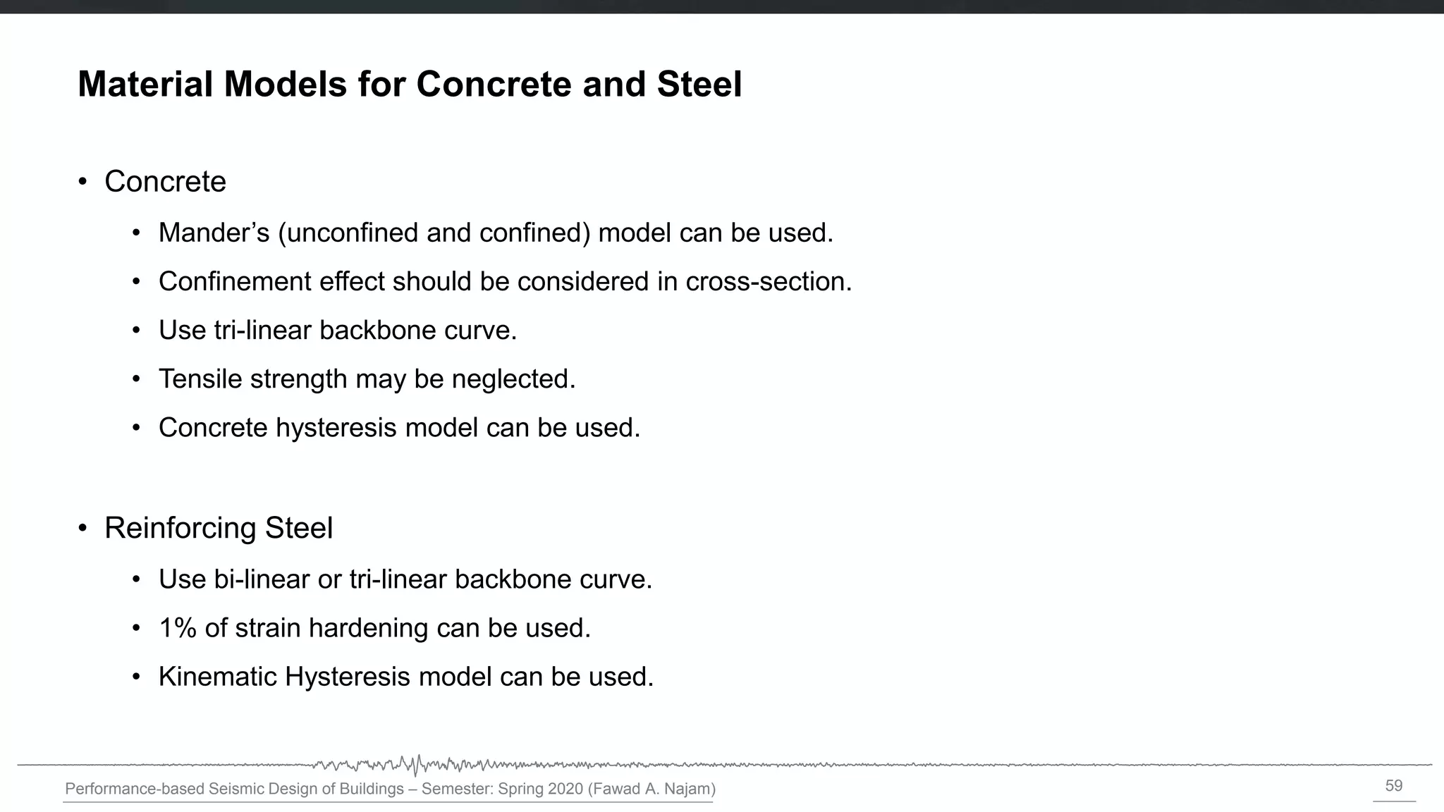
Material Models for Concrete and Steel
• Concrete
• Mander’s (unconfined and confined) model can be used.
• Confinement effect should be considered in cross-section.
• Use tri-linear backbone curve.
• Tensile strength may be neglected.
• Concrete hysteresis model can be used.
• Reinforcing Steel
• Use bi-linear or tri-linear backbone curve.
• 1% of strain hardening can be used.
• Kinematic Hysteresis model can be used.

![8
Performance-based Seismic Design of Buildings – Semester: Spring 2020 (Fawad A. Najam)
Fiber Model of Reinforced Concrete Beams
(a) Fiber section of a reinforced
concrete beam (Modified from
Powell [2006])
Linear-elastic frame element
Fiber segment (concrete and
steel fibers)
Beam cross-section
(b) Fiber segments at both
ends of a reinforced concrete
beam with Linear-elastic
frame element in-between.
The length of fiber segments
is a small fraction of the total
beam length.](https://image.slidesharecdn.com/1-fiber-modeling-approach-221120084653-8b158905/75/1-Fiber-Modeling-Approach-pdf-8-2048.jpg)
![9
Performance-based Seismic Design of Buildings – Semester: Spring 2020 (Fawad A. Najam)
Fiber Model of Reinforced Concrete Beams
• A common assumption for a beam is that there is inelastic bending in only one direction.
• To model bending behavior in the vertical direction, fibers are needed only through the depth of the beam,
as indicated in the figure.
• For horizontal bending an elastic bending stiffness is specified (i.e., an EI value). For vertical bending the
fiber model determines EI. For horizontal bending the model assumes that there is no P-M interaction. It
also assumes that there is no coupling between vertical and lateral bending [Powell 2006].](https://image.slidesharecdn.com/1-fiber-modeling-approach-221120084653-8b158905/75/1-Fiber-Modeling-Approach-pdf-9-2048.jpg)


![54
Performance-based Seismic Design of Buildings – Semester: Spring 2020 (Fawad A. Najam)
Steel Reinforcement – Hysteretic Response
Hysteretic response of reinforcing steel
[L.L. Dodd and J.I. Restrepo-Posada, 1995]
EPP-Model Bilinear Model (Clough) Ramberg-Osgood Model](https://image.slidesharecdn.com/1-fiber-modeling-approach-221120084653-8b158905/75/1-Fiber-Modeling-Approach-pdf-54-2048.jpg)
![55
Performance-based Seismic Design of Buildings – Semester: Spring 2020 (Fawad A. Najam)
Equivalent Plastic Hinge Length, LPH
max
( )
PH PH
PH length
x dx L
Empirical equations for Lph can be found in the literature
Concept of “Equivalent Plastic Hinge Length, LPH”
0.08 0.022
PH b y
L L d F
[Paulay and Priestley, 1992]](https://image.slidesharecdn.com/1-fiber-modeling-approach-221120084653-8b158905/75/1-Fiber-Modeling-Approach-pdf-55-2048.jpg)