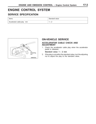
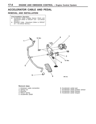
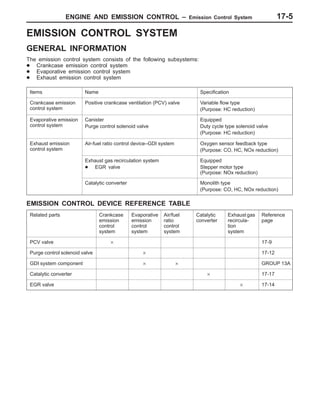
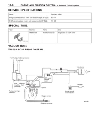
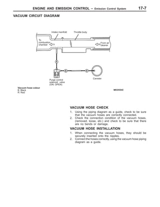
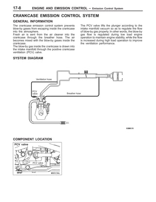
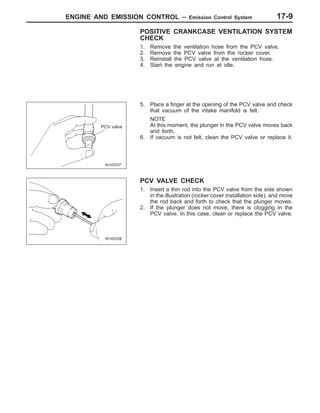
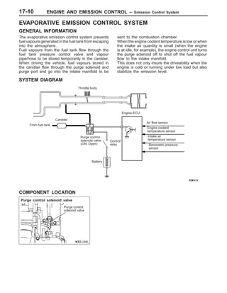
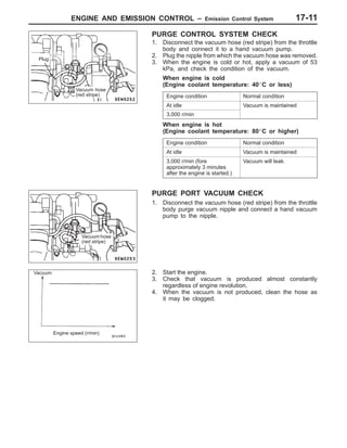
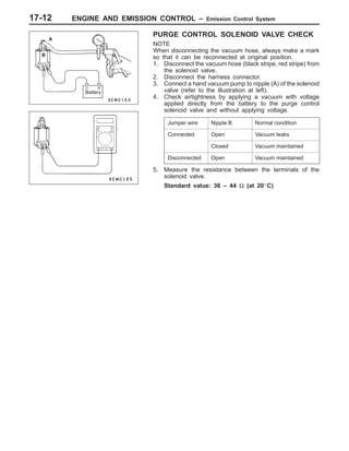
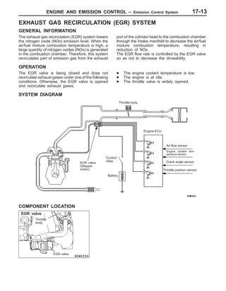
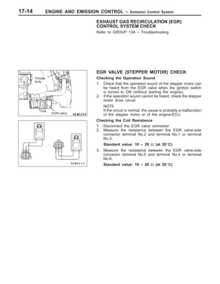
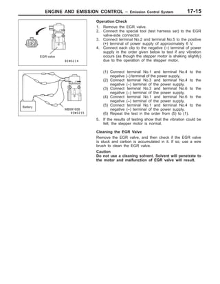
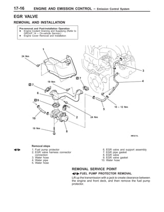
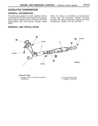
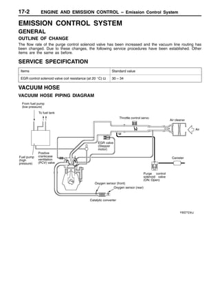
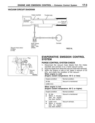
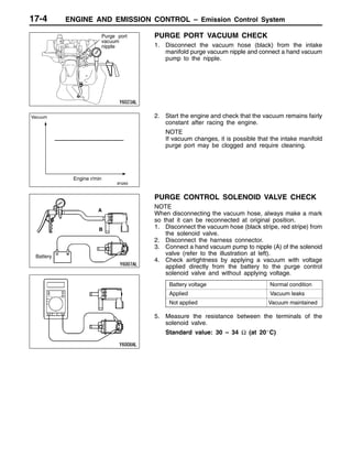
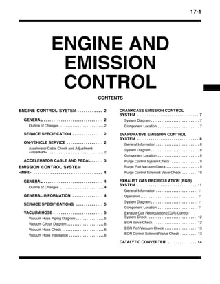
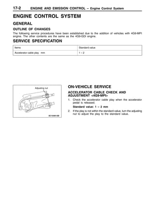
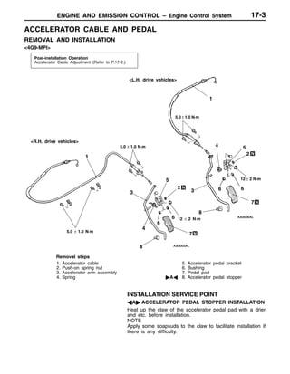
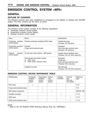
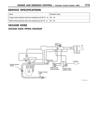
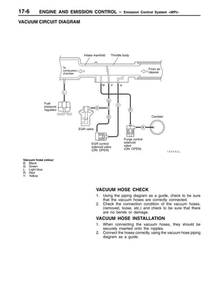
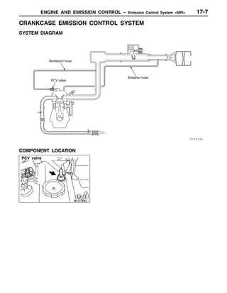
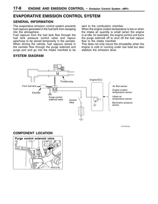
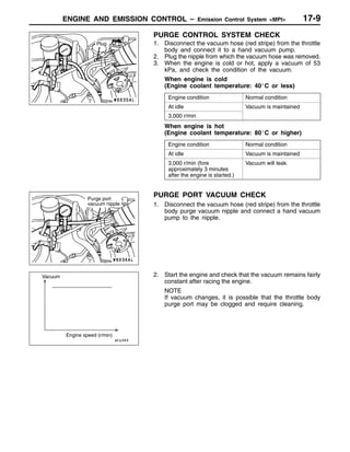
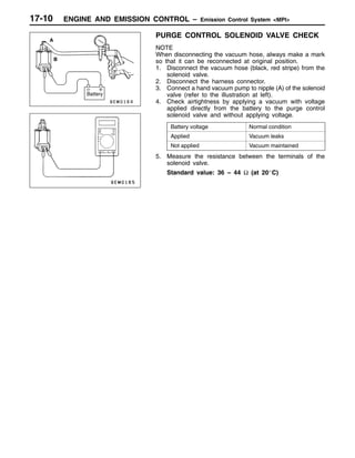
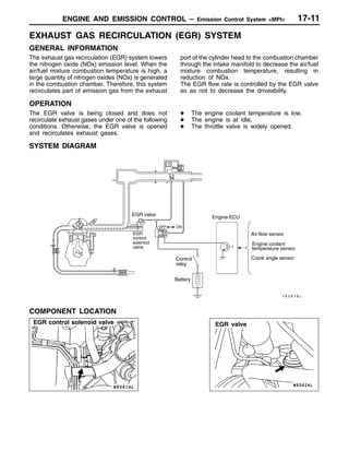
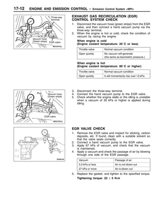
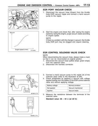
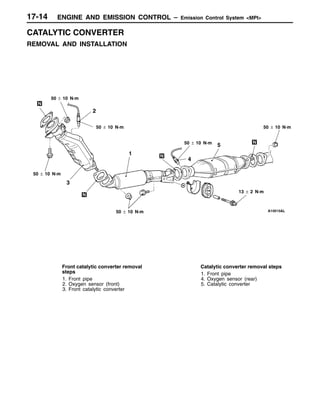
4. ENGINE AND EMISSION CONTROL – Engine Control System 17-3
ENGINE CONTROL SYSTEM
SERVICE SPECIFICATION
Items Standard value
Accelerator cable play mm 1 – 2
ON-VEHICLE SERVICE
ACCELERATOR CABLE CHECK AND
ADJUSTMENT
1. Check the accelerator cable play when the accelerator
pedal is released.
Standard value: 1 – 2 mm
2. If the play is not within the standard value, turn the adjusting
nut to adjust the play to the standard value.
Adjusting
nut
5. ENGINE AND EMISSION CONTROL – Engine Control System17-4
ACCELERATOR CABLE AND PEDAL
REMOVAL AND INSTALLATION
Post-installation Operation
D Accelerator Pedal Position Sensor Check and
Adjustment (Refer to GROUP 13A – On-vehicle
Service.)
D Kickdown Cable Adjustment (Refer to GROUP
23 – On-vehicle Service.)
12 Nm
2
9
5
1
6
8
3
7
10 Nm
4
Removal steps
1. Kickdown cable connection
2. Spring nut
3. Bushing
4. Return spring
5. Accelerator pedal
6. Accelerator pedal pad
7. Accelerator pedal position sensor
8. Accelerator pedal bracket
9. Accelerator pedal stopper
6. ENGINE AND EMISSION CONTROL – Emission Control System 17-5
EMISSION CONTROL SYSTEM
GENERAL INFORMATION
The emission control system consists of the following subsystems:
D Crankcase emission control system
D Evaporative emission control system
D Exhaust emission control system
Items Name Specification
Crankcase emission
control system
Positive crankcase ventilation (PCV) valve Variable flow type
(Purpose: HC reduction)
Evaporative emission
control system
Canister
Purge control solenoid valve
Equipped
Duty cycle type solenoid valve
(Purpose: HC reduction)
Exhaust emission
control system
Air-fuel ratio control device–GDI system Oxygen sensor feedback type
(Purpose: CO, HC, NOx reduction)
Exhaust gas recirculation system
D EGR valve
Equipped
Stepper motor type
(Purpose: NOx reduction)
Catalytic converter Monolith type
(Purpose: CO, HC, NOx reduction)
EMISSION CONTROL DEVICE REFERENCE TABLE
Related parts Crankcase
emission
control
system
Evaporative
emission
control
system
Air/fuel
ratio
control
system
Catalytic
converter
Exhaust gas
recircula-
tion
system
Reference
page
PCV valve × 17-9
Purge control solenoid valve × 17-12
GDI system component × × GROUP 13A
Catalytic converter × 17-17
EGR valve × 17-14
7. ENGINE AND EMISSION CONTROL – Emission Control System17-6
SERVICE SPECIFICATIONS
Items Standard value
Purge control solenoid valve coil resistance (at 20_C) Ω 36 – 44
EGR valve (stepper motor) coil resistance (at 20_C) Ω 10 – 20
SPECIAL TOOL
Tool Number Name Use
MB991658 Test harness set Inspection of EGR valve
VACUUM HOSE
VACUUM HOSE PIPING DIAGRAM
PCV
valve
From fuel pump (low-pressure)
Canister
Purge control
solenoid valve
Oxygen sensor
Fuel pressure
regulator (high-
pressure)
To fuel tank
EGR valve
(stepper
motor)
P
Catalytic converter
Fuel pump (high-
pressure)
Injector
Air cleaner
Air
8. ENGINE AND EMISSION CONTROL – Emission Control System 17-7
VACUUM CIRCUIT DIAGRAM
To
combustion
chamber
Intake manifold Throttle body
From air
cleaner
Vacuum hose colour
B: Black
R: Red
Purge control
solenoid valve
(ON: OPEN)
Canister
VACUUM HOSE CHECK
1. Using the piping diagram as a guide, check to be sure
that the vacuum hoses are correctly connected.
2. Check the connection condition of the vacuum hoses,
(removed, loose, etc.) and check to be sure that there
are no bends or damage.
VACUUM HOSE INSTALLATION
1. When connecting the vacuum hoses, they should be
securely inserted onto the nipples.
2. Connect the hoses correctly, using the vacuum hose piping
diagram as a guide.
9. ENGINE AND EMISSION CONTROL – Emission Control System
PCV valve
PCV valve
17-8
CRANKCASE EMISSION CONTROL SYSTEM
GENERAL INFORMATION
The crankcase emission control system prevents
blow-by gases from escaping inside the crankcase
into the atmosphere.
Fresh air is sent from the air cleaner into the
crankcase through the breather hose. The air
becomes mixed with the blow-by gases inside the
crankcase.
The blow-by gas inside the crankcase is drawn into
the intake manifold through the positive crankcase
ventilation (PCV) valve.
The PCV valve lifts the plunger according to the
intake manifold vacuum so as to regulate the flow
of blow-by gas properly. In other words, the blow-by
gas flow is regulated during low load engine
operation to maintain engine stability, while the flow
is increased during high load operation to improve
the ventilation performance.
SYSTEM DIAGRAM
PCV
valve
Ventilation hose
Breather hose
COMPONENT LOCATION
10. ENGINE AND EMISSION CONTROL – Emission Control System 17-9
POSITIVE CRANKCASE VENTILATION SYSTEM
CHECK
1. Remove the ventilation hose from the PCV valve.
2. Remove the PCV valve from the rocker cover.
3. Reinstall the PCV valve at the ventilation hose.
4. Start the engine and run at idle.
5. Place a finger at the opening of the PCV valve and check
that vacuum of the intake manifold is felt.
NOTE
At this moment, the plunger in the PCV valve moves back
and forth.
6. If vacuum is not felt, clean the PCV valve or replace it.
PCV VALVE CHECK
1. Insert a thin rod into the PCV valve from the side shown
in the illustration (rocker cover installation side), and move
the rod back and forth to check that the plunger moves.
2. If the plunger does not move, there is clogging in the
PCV valve. In this case, clean or replace the PCV valve.
PCV valve
11. ENGINE AND EMISSION CONTROL – Emission Control System
Purge control solenoid valve
Purge control
solenoid valve
17-10
EVAPORATIVE EMISSION CONTROL SYSTEM
GENERAL INFORMATION
The evaporative emission control system prevents
fuel vapours generated in the fuel tank from escaping
into the atmosphere.
Fuel vapours from the fuel tank flow through the
fuel tank pressure control valve and vapour
pipe/hose to be stored temporarily in the canister.
When driving the vehicle, fuel vapours stored in
the canister flow through the purge solenoid and
purge port and go into the intake manifold to be
sent to the combustion chamber.
When the engine coolant temperature is low or when
the intake air quantity is small (when the engine
is at idle, for example), the engine control unit turns
the purge solenoid off to shut off the fuel vapour
flow to the intake manifold.
This does not only insure the driveability when the
engine is cold or running under low load but also
stabilize the emission level.
SYSTEM DIAGRAM
From fuel tank
Canister
Purge control
solenoid valve
(ON: Open)
Air flow sensor
Barometric pressure
sensor
Control
relay
Throttle body
Engine-ECU
Engine coolant
temperature sensor
Intake air
temperature sensor
Battery
COMPONENT LOCATION
12. ENGINE AND EMISSION CONTROL – Emission Control System 17-11
PURGE CONTROL SYSTEM CHECK
1. Disconnect the vacuum hose (red stripe) from the throttle
body and connect it to a hand vacuum pump.
2. Plug the nipple from which the vacuum hose was removed.
3. When the engine is cold or hot, apply a vacuum of 53
kPa, and check the condition of the vacuum.
When engine is cold
(Engine coolant temperature: 40_C or less)
Engine condition Normal condition
At idle Vacuum is maintained
3,000 r/min
When engine is hot
(Engine coolant temperature: 80_C or higher)
Engine condition Normal condition
At idle Vacuum is maintained
3,000 r/min (fore
approximately 3 minutes
after the engine is started.)
Vacuum will leak.
PURGE PORT VACUUM CHECK
1. Disconnect the vacuum hose (red stripe) from the throttle
body purge vacuum nipple and connect a hand vacuum
pump to the nipple.
2. Start the engine.
3. Check that vacuum is produced almost constantly
regardless of engine revolution.
4. When the vacuum is not produced, clean the hose as
it may be clogged.
Plug
Vacuum hose
(red stripe)
Vacuum hose
(red stripe)
Vacuum
Engine speed (r/min)
13. ENGINE AND EMISSION CONTROL – Emission Control System17-12
PURGE CONTROL SOLENOID VALVE CHECK
NOTE
When disconnecting the vacuum hose, always make a mark
so that it can be reconnected at original position.
1. Disconnect the vacuum hose (black stripe, red stripe) from
the solenoid valve.
2. Disconnect the harness connector.
3. Connect a hand vacuum pump to nipple (A) of the solenoid
valve (refer to the illustration at left).
4. Check airtightness by applying a vacuum with voltage
applied directly from the battery to the purge control
solenoid valve and without applying voltage.
Jumper wire Nipple B Normal condition
Connected Open Vacuum leaks
Closed Vacuum maintained
Disconnected Open Vacuum maintained
5. Measure the resistance between the terminals of the
solenoid valve.
Standard value: 36 – 44 Ω (at 20_C)
Battery
B
A
14. ENGINE AND EMISSION CONTROL – Emission Control System
EGR valve
Throttle
body
EGR valve
17-13
EXHAUST GAS RECIRCULATION (EGR) SYSTEM
GENERAL INFORMATION
The exhaust gas recirculation (EGR) system lowers
the nitrogen oxide (NOx) emission level. When the
air/fuel mixture combustion temperature is high, a
large quantity of nitrogen oxides (NOx) is generated
in the combustion chamber. Therefore, this system
recirculates part of emission gas from the exhaust
port of the cylinder head to the combustion chamber
through the intake manifold to decrease the air/fuel
mixture combustion temperature, resulting in
reduction of NOx.
The EGR flow rate is controlled by the EGR valve
so as not to decrease the driveability.
OPERATION
The EGR valve is being closed and dose not
recirculate exhaust gases under one of the following
conditions. Otherwise, the EGR valve is opened
and recirculate exhaust gases.
D The engine coolant temperature is low.
D The engine is at idle.
D The throttle valve is widely opened.
SYSTEM DIAGRAM
Air flow sensor
Engine coolant tem-
perature sensor
Crank angle sensor
Control
relay
Engine-ECU
Battery
Throttle body
EGR valve
(Stepper
motor) Throttle position sensor
COMPONENT LOCATION
15. ENGINE AND EMISSION CONTROL – Emission Control System17-14
EXHAUST GAS RECIRCULATION (EGR)
CONTROL SYSTEM CHECK
Refer to GROUP 13A – Troubleshooting.
EGR VALVE (STEPPER MOTOR) CHECK
Checking the Operation Sound
1. Check that the operation sound of the stepper motor can
be heard from the EGR valve when the ignition switch
is turned to ON (without starting the engine).
2. If the operation sound cannot be heard, check the stepper
motor drive circuit.
NOTE
If the circuit is normal, the cause is probably a malfunction
of the stepper motor or of the engine-ECU.
Checking the Coil Resistance
1. Disconnect the EGR valve connector.
2. Measure the resistance between the EGR valve-side
connector terminal No.2 and terminal No.1 or terminal
No.3.
Standard value: 10 – 20 Ω (at 20_C)
3. Measure the resistance between the EGR valve-side
connector terminal No.5 and terminal No.4 or terminal
No.6.
Standard value: 10 – 20 Ω (at 20_C)
Throttle
body
EGR valve
16. ENGINE AND EMISSION CONTROL – Emission Control System 17-15
Operation Check
1. Remove the EGR valve.
2. Connect the special tool (test harness set) to the EGR
valve-side connector.
3. Connect terminal No.2 and terminal No.5 to the positive
(+) terminal of power supply of approximately 6 V.
4. Connect each clip to the negative (–) terminal of power
supply in the order given below to test if any vibration
occurs (as though the stepper motor is shaking slightly)
due to the operation of the stepper motor.
(1) Connect terminal No.1 and terminal No.4 to the
negative (–) terminal of the power supply.
(2) Connect terminal No.3 and terminal No.4 to the
negative (–) terminal of the power supply.
(3) Connect terminal No.3 and terminal No.6 to the
negative (–) terminal of the power supply.
(4) Connect terminal No.1 and terminal No.6 to the
negative (–) terminal of the power supply.
(5) Connect terminal No.1 and terminal No.4 to the
negative (–) terminal of the power supply.
(6) Repeat the test in the order from (5) to (1).
5. If the results of testing show that the vibration could be
felt, the stepper motor is normal.
Cleaning the EGR Valve
Remove the EGR valve, and then check if the EGR valve
is stuck and carbon is accumulated in it. If so, use a wire
brush to clean the EGR valve.
Caution
Do not use a cleaning solvent. Solvent will penetrate to
the motor and malfunction of EGR valve will result.
EGR valve
Battery
MB991658
17. ENGINE AND EMISSION CONTROL – Emission Control System17-16
EGR VALVE
REMOVAL AND INSTALLATION
Pre-removal and Post-installation Operation
D Engine Coolant Draining and Supplying (Refer to
GROUP 14 – On-vehicle Service.)
D Engine Cover Removal and Installation
1
9
24 Nm
24 Nm
19 Nm
10
19 Nm
8
7
5
2
3
10 – 12 Nm
4
7
6
Removal steps
AA" 1. Fuel pump protector
2. EGR valve harness connector
connection
3. Water hose
4. Water pipe
5. Water hose
6. EGR valve and support assembly
7. EGR pipe gasket
8. EGR valve
9. EGR valve gasket
10. Water hose
REMOVAL SERVICE POINT
AA" FUEL PUMP PROTECTOR REMOVAL
Lift up the transmission with a jack to create clearance between
the engine and front deck, and then remove the fuel pump
protector.
18. ENGINE AND EMISSION CONTROL – Emission Control System 17-17
CATALYTIC CONVERTER
GENERAL INFORMATION
The three-way catalytic converter, together with the
closed loop air-fuel ratio control based on the oxygen
sensor signal, oxidizes carbon monoxides (CO) and
hydrocarbons (HC) and reduces nitrogen oxides
(NOx).
When the mixture is controlled at stoichiometric
air-fuel ratio, the three-way catalytic converter
provides the highest purification against the three
constituents, namely, CO, HC and NOx.
REMOVAL AND INSTALLATION
49 Nm
49 Nm
34 Nm
49 Nm
1
2
3
Removal steps
1. Oxygen sensor harness connector
connection
2. Front exhaust pipe
3. Catalytic converter
21. ENGINE AND EMISSION CONTROL – Emission Control System17-2
EMISSION CONTROL SYSTEM
GENERAL
OUTLINE OF CHANGE
The flow rate of the purge control solenoid valve has been increased and the vacuum line routing has
been changed. Due to these changes, the following service procedures have been established. Other
items are the same as before.
SERVICE SPECIFICATION
Items Standard value
EGR control solenoid valve coil resistance (at 20 _C) Ω 30 – 34
VACUUM HOSE
VACUUM HOSE PIPING DIAGRAM
Air cleaner
Fuel pump
(high
pressure)
Throttle control servo
Canister
Purge control
solenoid valve
(ON: Open)
EGR valve
(Stepper
motor)
Oxygen sensor (front)
Oxygen sensor (rear)
Catalytic converter
Air
From fuel pump
(low pressure)
To fuel tank
Positive
crankcase
ventilation
(PCV) valve
M
22. ENGINE AND EMISSION CONTROL – Emission Control System 17-3
VACUUM CIRCUIT DIAGRAM
To
combustion
chamber
Intake manifold Throttle body
From air
cleaner
EGR control
solenoid
valve (ON:
OPEN)Vacuum hose colour
B: Black
R: Red
Canister
M
EVAPORATIVE EMISSION CONTROL
SYSTEM
PURGE CONTROL SYSTEM CHECK
1. Disconnect the vacuum hose (black) from the intake
manifold and connect it to a hand vacuum pump.
2. Plug the nipple from which the vacuum hose was removed.
3. When the engine is cold or hot, apply a vacuum of 53
kPa, and check the condition of the vacuum.
When engine is cold
(Engine coolant temperature: 40_C or less)
Engine condition Normal condition
At idle Vacuum is maintained
3,000 r/min
When engine is hot
(Engine coolant temperature: 80_C or higher)
Engine condition Normal condition
D At idle
D Within 4 minutes
after the engine
has been started
Vacuum is maintained
D 3,000 r/min
D Within 3 minutes
after the engine
has been started
Vacuum will leak.
Plug
Vacuum
hose
(black)
23. ENGINE AND EMISSION CONTROL – Emission Control System17-4
PURGE PORT VACUUM CHECK
1. Disconnect the vacuum hose (black) from the intake
manifold purge vacuum nipple and connect a hand vacuum
pump to the nipple.
2. Start the engine and check that the vacuum remains fairly
constant after racing the engine.
NOTE
If vacuum changes, it is possible that the intake manifold
purge port may be clogged and require cleaning.
PURGE CONTROL SOLENOID VALVE CHECK
NOTE
When disconnecting the vacuum hose, always make a mark
so that it can be reconnected at original position.
1. Disconnect the vacuum hose (black stripe, red stripe) from
the solenoid valve.
2. Disconnect the harness connector.
3. Connect a hand vacuum pump to nipple (A) of the solenoid
valve (refer to the illustration at left).
4. Check airtightness by applying a vacuum with voltage
applied directly from the battery to the purge control
solenoid valve and without applying voltage.
Battery voltage Normal condition
Applied Vacuum leaks
Not applied Vacuum maintained
5. Measure the resistance between the terminals of the
solenoid valve.
Standard value: 30 – 34 Ω (at 20_C)
Purge port
vacuum
nipple
Engine r/min
Vacuum
A
B
B
Battery
25. ENGINE AND EMISSION CONTROL – Engine Control System17-2
ENGINE CONTROL SYSTEM
GENERAL
OUTLINE OF CHANGES
The following service procedures have been established due to the addition of vehicles with 4G9-MPI
engine. The other contents are the same as the 4G9-GDI engine.
SERVICE SPECIFICATION
Items Standard value
Accelerator cable play mm 1 – 2
ON-VEHICLE SERVICE
ACCELERATOR CABLE CHECK AND
ADJUSTMENT <4G9-MPI>
1. Check the accelerator cable play when the accelerator
pedal is released.
Standard value: 1 – 2 mm
2. If the play is not within the standard value, turn the adjusting
nut to adjust the play to the standard value.
Adjusting nut
26. ENGINE AND EMISSION CONTROL – Engine Control SystemENGINE AND EMISSION CONTROL – Engine Control System 17-3
ACCELERATOR CABLE AND PEDAL
REMOVAL AND INSTALLATION
<4G9-MPI>
Post-installation Operation
Accelerator Cable Adjustment (Refer to P.17-2.)
1
2
3
2
4
<L.H. drive vehicles>
<R.H. drive vehicles>
8
6
5
7
5
3
4
6
7
8
1
5.0 ± 1.0 N·m
6
6
45.0 ± 1.0 N·m
5.0 ± 1.0 N·m
12 ± 2 N·m
12 ± 2 N·m
Removal steps
1. Accelerator cable
2. Push-on spring nut
3. Accelerator arm assembly
4. Spring
5. Accelerator pedal bracket
6. Bushing
7. Pedal pad
"AA 8. Accelerator pedal stopper
INSTALLATION SERVICE POINT
AA" ACCELERATOR PEDAL STOPPER INSTALLATION
Heat up the claw of the accelerator pedal pad with a drier
and etc. before installation.
NOTE
Apply some soapsuds to the claw to facilitate installation if
there is any difficulty.
27. ENGINE AND EMISSION CONTROL – Emission Control System <MPI>17-4
EMISSION CONTROL SYSTEM <MPI>
GENERAL
OUTLINE OF CHANGES
The following contents have been established to correspond to the addition of vehicles with 4G9-MPI
engine. The other contents are the same as before.
GENERAL INFORMATION
The emission control system consists of the following subsystems:
D Crankcase emission control system
D Evaporative emission control system
D Exhaust emission control system
Items Name Specification
Crankcase emission
control system
Positive crankcase ventilation (PCV) valve Variable flow type
(Purpose: HC reduction)
Evaporative emission
control system
Canister
Purge control solenoid valve
Equipped
Duty cycle type solenoid valve
(Purpose: HC reduction)
Exhaust emission
control system
Air-fuel ratio control device – MPI system Oxygen sensor feedback type
(Purpose: CO, HC, NOx reduction)
Exhaust gas recirculation system
D EGR valve
D EGR control solenoid valve
Equipped
Single type
Duty cycle type solenoid valve
(Purpose: NOx reduction)
Catalytic converter Monolith type
(Purpose: CO, HC, NOx reduction)
EMISSION CONTROL DEVICE REFERENCE TABLE
Related parts Crankcase
emission
control
system
Evaporative
emission
control
system
Air/fuel
ratio
control
system
Catalytic
converter
Exhaust
gas
recircula-
tion system
Reference
page
PCV valve × 17-9*
Purge control solenoid valve × 17-9
MPI system component × × GROUP 13B
Catalytic converter × 17-14
EGR valve × 17-12
EGR control solenoid valve × 17-13
NOTE
*: Refer to the ’00 PAJERO PININ Workshop Manual (Pub. No. CKRE00E1)
28. ENGINE AND EMISSION CONTROL – Emission Control System <MPI> 17-5
SERVICE SPECIFICATIONS
Items Standard value
Purge control solenoid valve coil resistance (at 20_C) Ω 36 – 44
EGR control solenoid valve coil resistance (at 20_C) Ω 36 – 44
VACUUM HOSE
VACUUM HOSE PIPING DIAGRAM
PCV valve
OFF
EGR valve
Air cleaner
ON
Canister
Purge control
solenoid valve
EGR control
solenoid valve
Oxygen sensor
<rear>
Air
OFF ON
Oxygen sensor
<front>
M E A
29. ENGINE AND EMISSION CONTROL – Emission Control System <MPI>17-6
VACUUM CIRCUIT DIAGRAM
From air
cleaner
Intake manifold Throttle body
To
combustion
chamber
Fuel
pressure
regulator
EGR control
solenoid valve
(ON: OPEN)
Canister
Purge control
solenoid
valve
(ON: OPEN)
EGR valve
Vacuum hose colour
B: Black
G: Green
L: Light blue
R: Red
Y: Yellow
M P A
L
G
Y
G
G
R
B
VACUUM HOSE CHECK
1. Using the piping diagram as a guide, check to be sure
that the vacuum hoses are correctly connected.
2. Check the connection condition of the vacuum hoses,
(removed, loose, etc.) and check to be sure that there
are no bends or damage.
VACUUM HOSE INSTALLATION
1. When connecting the vacuum hoses, they should be
securely inserted onto the nipples.
2. Connect the hoses correctly, using the vacuum hose piping
diagram as a guide.
30. ENGINE AND EMISSION CONTROL – Emission Control System <MPI>
PCV valve
17-7
CRANKCASE EMISSION CONTROL SYSTEM
SYSTEM DIAGRAM
Ventilation hose
Breather hose
PCV valve
COMPONENT LOCATION
31. ENGINE AND EMISSION CONTROL – Emission Control System <MPI>
Purge control solenoid valve
17-8
EVAPORATIVE EMISSION CONTROL SYSTEM
GENERAL INFORMATION
The evaporative emission control system prevents
fuel vapours generated in the fuel tank from escaping
into the atmosphere.
Fuel vapours from the fuel tank flow through the
fuel tank pressure control valve and vapour
pipe/hose to be stored temporarily in the canister.
When driving the vehicle, fuel vapours stored in
the canister flow through the purge solenoid and
purge port and go into the intake manifold to be
sent to the combustion chamber.
When the engine coolant temperature is low or when
the intake air quantity is small (when the engine
is at idle, for example), the engine control unit turns
the purge solenoid off to shut off the fuel vapour
flow to the intake manifold.
This does not only insure the driveability when the
engine is cold or running under low load but also
stabilize the emission level.
SYSTEM DIAGRAM
From fuel tank
Canister
Purge control
solenoid valve
OFF
ON
Air flow sensor
Barometric pressure
sensor
Control
relay
Throttle body
Engine-ECU
Engine coolant
temperature sensor
Intake air
temperature sensor
COMPONENT LOCATION
32. ENGINE AND EMISSION CONTROL – Emission Control System <MPI> 17-9
PURGE CONTROL SYSTEM CHECK
1. Disconnect the vacuum hose (red stripe) from the throttle
body and connect it to a hand vacuum pump.
2. Plug the nipple from which the vacuum hose was removed.
3. When the engine is cold or hot, apply a vacuum of 53
kPa, and check the condition of the vacuum.
When engine is cold
(Engine coolant temperature: 40_C or less)
Engine condition Normal condition
At idle Vacuum is maintained
3,000 r/min
When engine is hot
(Engine coolant temperature: 80_C or higher)
Engine condition Normal condition
At idle Vacuum is maintained
3,000 r/min (fore
approximately 3 minutes
after the engine is started.)
Vacuum will leak.
PURGE PORT VACUUM CHECK
1. Disconnect the vacuum hose (red stripe) from the throttle
body purge vacuum nipple and connect a hand vacuum
pump to the nipple.
2. Start the engine and check that the vacuum remains fairly
constant after racing the engine.
NOTE
If vacuum changes, it is possible that the throttle body
purge port may be clogged and require cleaning.
Plug
Purge port
vacuum nipple
Vacuum
Engine speed (r/min)
33. ENGINE AND EMISSION CONTROL – Emission Control System <MPI>17-10
PURGE CONTROL SOLENOID VALVE CHECK
NOTE
When disconnecting the vacuum hose, always make a mark
so that it can be reconnected at original position.
1. Disconnect the vacuum hose (black, red stripe) from the
solenoid valve.
2. Disconnect the harness connector.
3. Connect a hand vacuum pump to nipple (A) of the solenoid
valve (refer to the illustration at left).
4. Check airtightness by applying a vacuum with voltage
applied directly from the battery to the purge control
solenoid valve and without applying voltage.
Battery voltage Normal condition
Applied Vacuum leaks
Not applied Vacuum maintained
5. Measure the resistance between the terminals of the
solenoid valve.
Standard value: 36 – 44 Ω (at 20_C)
Battery
B
A
34. ENGINE AND EMISSION CONTROL – Emission Control System <MPI>
EGR control solenoid valve EGR valve
17-11
EXHAUST GAS RECIRCULATION (EGR) SYSTEM
GENERAL INFORMATION
The exhaust gas recirculation (EGR) system lowers
the nitrogen oxide (NOx) emission level. When the
air/fuel mixture combustion temperature is high, a
large quantity of nitrogen oxides (NOx) is generated
in the combustion chamber. Therefore, this system
recirculates part of emission gas from the exhaust
port of the cylinder head to the combustion chamber
through the intake manifold to decrease the air/fuel
mixture combustion temperature, resulting in
reduction of NOx.
The EGR flow rate is controlled by the EGR valve
so as not to decrease the driveability.
OPERATION
The EGR valve is being closed and does not
recirculate exhaust gases under one of the following
conditions. Otherwise, the EGR valve is opened
and recirculates exhaust gases.
D The engine coolant temperature is low.
D The engine is at idle.
D The throttle valve is widely opened.
SYSTEM DIAGRAM
ONOFF
EGR
control
solenoid
valve
Air flow sensor
Engine coolant
temperature sensor
Crank angle sensorControl
relay
Engine-ECU
Battery
EGR valve
COMPONENT LOCATION
35. ENGINE AND EMISSION CONTROL – Emission Control System <MPI>17-12
EXHAUST GAS RECIRCULATION (EGR)
CONTROL SYSTEM CHECK
1. Disconnect the vacuum hose (green stripe) from the EGR
valve, and then connect a hand vacuum pump via the
three-way terminal.
2. When the engine is hot or cold, check the condition of
vacuum by racing the engine.
When engine is cold
(Engine coolant temperature: 20_C or less)
Throttle valve Normal vacuum condition
Open quickly No vacuum will generate
(the same as barometric pressure.)
When engine is hot
(Engine coolant temperature: 80_C or higher)
Throttle valve Normal vacuum condition
Open quickly It will momentarily rise over 13 kPa
3. Disconnect the three-way terminal.
4. Connect the hand vacuum pump to the EGR valve.
5. Check whether the engine stalls or the idling is unstable
when a vacuum of 30 kPa or higher is applied during
idling.
EGR VALVE CHECK
1. Remove the EGR valve and inspect for sticking, carbon
deposits, etc. If found, clean with a suitable solvent so
that the valve seats correctly.
2. Connect a hand vacuum pump to the EGR valve.
3. Apply 67 kPa of vacuum, and check that the vacuum
is maintained.
4. Apply a vacuum and check the passage of air by blowing
through one side of the EGR passage.
Vacuum Passage of air
5.0 kPa or less Air is not blown out
27 kPa or more Air is blown out
5. Replace the gasket, and tighten to the specified torque.
Tightening torque: 22 ± 5 N·m
Three-way
terminal
Vacuum hose
(Green stripe) EGR valve
EGR valve
Plug Vacuum hose
(Green stripe)
36. ENGINE AND EMISSION CONTROL – Emission Control System <MPI> 17-13
EGR PORT VACUUM CHECK
1. Disconnect the vacuum hose (Green) from the throttle
body EGR vacuum nipple and connect a hand vacuum
pump to the nipple.
2. Start the engine and check that, after raising the engine
speed by racing the engine, purge vacuum raises according
to engine speed.
NOTE
If there is a problem with the change in vacuum, the throttle
body EGR port may be clogged and require cleaning.
EGR CONTROL SOLENOID VALVE CHECK
NOTE
When disconnecting the vacuum hose, always make a mark
so that it can be reconnected at original position.
1. Disconnect the vacuum hose (yellow stripe, green stripe)
from the solenoid valve.
2. Disconnect the harness connector.
3. Connect a hand vacuum pump to the nipple (A) of the
solenoid valve (refer to the illustration at left).
4. Check airtightness by applying a vacuum with voltage
applied directly from the battery to the EGR control solenoid
valve and without applying voltage.
Battery voltage Normal condition
Not applied Vacuum maintained
Applied Vacuum leaks
5. Measure the resistance between the terminals of the
solenoid valve.
Standard value: 36 – 44 Ω (at 20_C)
Vacuum
Engine speed (r/min)
A
B
Battery
37. ENGINE AND EMISSION CONTROL – Emission Control System <MPI>17-14
CATALYTIC CONVERTER
REMOVAL AND INSTALLATION
1
2
4
3
5
50 ± 10 N·m
50 ± 10 N·m
50 ± 10 N·m
50 ± 10 N·m
50 ± 10 N·m
50 ± 10 N·m
13 ± 2 N·m
Front catalytic converter removal
steps
1. Front pipe
2. Oxygen sensor (front)
3. Front catalytic converter
Catalytic converter removal steps
1. Front pipe
4. Oxygen sensor (rear)
5. Catalytic converter