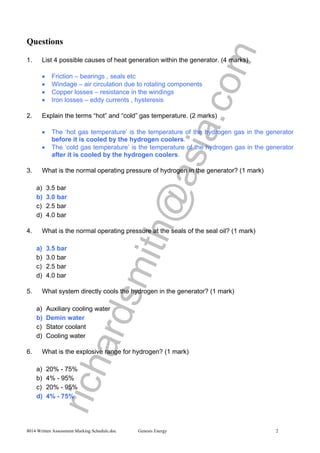
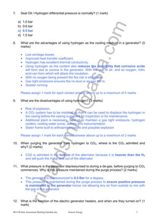
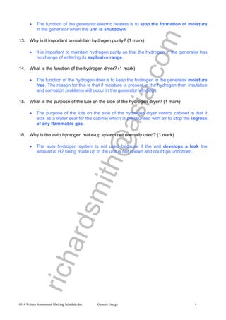
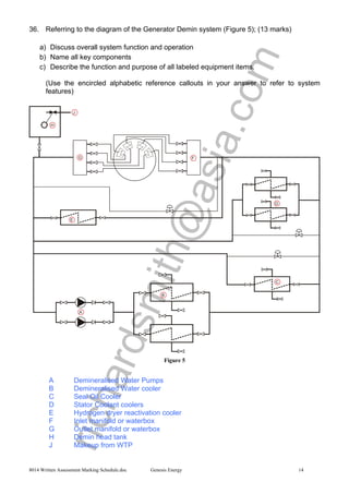
SlideShare a Scribd company logo
richardsmith@asia.com
Generator, Unit Hydrogen, Seal Oil,
Stator Coolant, Demin Water
Plant Operations Training
Huntly Power Station: Units 1-4
Assessment ID: 8014, 8012, 8009, 8015, 8016
NZQA Unit Standard: 17413
Assessment Marking Schedule
/107 marks
richardsmith@asia.com
8014 Written Assessment Marking Schedule.doc Genesis Energy 2
Questions
1. List 4 possible causes of heat generation within the generator. (4 marks)
• Friction – bearings , seals etc
• Windage – air circulation due to rotating components
• Copper losses – resistance in the windings
• Iron losses – eddy currents , hysteresis
2. Explain the terms “hot” and “cold” gas temperature. (2 marks)
• The ‘hot gas temperature’ is the temperature of the hydrogen gas in the generator
before it is cooled by the hydrogen coolers.
• The ‘cold gas temperature’ is the temperature of the hydrogen gas in the generator
after it is cooled by the hydrogen coolers.
3. What is the normal operating pressure of hydrogen in the generator? (1 mark)
a) 3.5 bar
b) 3.0 bar
c) 2.5 bar
d) 4.0 bar
4. What is the normal operating pressure at the seals of the seal oil? (1 mark)
a) 3.5 bar
b) 3.0 bar
c) 2.5 bar
d) 4.0 bar
5. What system directly cools the hydrogen in the generator? (1 mark)
a) Auxiliary cooling water
b) Demin water
c) Stator coolant
d) Cooling water
6. What is the explosive range for hydrogen? (1 mark)
a) 20% - 75%
b) 4% - 95%
c) 20% - 95%
d) 4% - 75%
richardsmith@asia.com
8014 Written Assessment Marking Schedule.doc Genesis Energy 3
7. Seal Oil / Hydrogen differential pressure is normally? (1 mark)
a) 1.0 bar
b) 0.6 bar
c) 0.5 bar
d) 1.5 bar
8. What are the advantages of using hydrogen as the cooling medium in a generator? (5
marks)
• Low windage losses.
• Improved heat transfer coefficient.
• Hydrogen has excellent thermal conductivity.
• Using hydrogen as the coolant also reduces the possibility that corrosive acids
will form due to corona in the generator. With the use of air, and so oxygen, nitric
acid can form which will attack the insulation.
• With no oxygen being present the fire risk is eliminated.
• Gas tight enclosure ensures the no dust or air can get in.
• Quieter running
Please assign 1 mark for each correct answer above up to a maximum of 5 marks
9. What are the disadvantages of using hydrogen? (3 marks)
• Risk of explosion.
• A CO2 system has to be installed so that it can be used to displace the hydrogen in
the casing before the casing is opened for inspection or for maintenance.
• Additional plant is necessary. Seal oil to maintain a gas tight enclosure, hydrogen
coolers, cooling water pump, alarms and instrumentation
• Stator frame built to withstand pressure and possible explosion
Please assign 1 mark for each correct answer above up to a maximum of 3 marks
10. When purging the generator from hydrogen to CO2, where is the CO2 admitted and
why? (2 marks)
• CO2 is admitted in the bottom of the alternator because it is heavier than the H2
and will push the H2 up and out of the alternator
11. What pressure is the generator depressurised to during a de-gas, before purging to CO2
commences. Why is this pressure maintained during the purge process? (2 marks)
• The generator is depressurized to 0.5 Bar for a degass.
• This pressure is maintained during the purge process to ensure positive pressure
is maintained in the generator hence not allowing any air from outside to mix with
the gas in the generator.
12. What is the function of the electric generator heaters, and when are they turned on? (1
mark)
richardsmith@asia.com
8014 Written Assessment Marking Schedule.doc Genesis Energy 4
• The function of the generator electric heaters is to stop the formation of moisture
in the generator when the unit is shutdown.
13. Why is it important to maintain hydrogen purity? (1 mark)
• It is important to maintain hydrogen purity so that the hydrogen in the generator has
no change of entering its explosive range.
14. What is the function of the hydrogen dryer? (1 mark)
• The function of the hydrogen drier is to keep the hydrogen in the generator moisture
free. The reason for this is that if moisture is present in the hydrogen then insulation
and corrosion problems will occur in the generator windings.
15. What is the purpose of the lute on the side of the hydrogen dryer? (1 mark)
• The purpose of the lute on the side of the hydrogen dryer control cabinet is that it
acts as a water seal for the cabinet which is pressurised with air to stop the ingress
of any flammable gas.
16. Why is the auto hydrogen make-up system not normally used? (1 mark)
• The auto hydrogen system is not used because if the unit develops a leak the
amount of H2 being made up to the unit is not known and could go unnoticed.
richardsmith@asia.com
8014 Written Assessment Marking Schedule.doc Genesis Energy 5
17. Referring to the diagram of the seal oil system (Figure 1); (15 marks)
a) Discuss overall system function and operation.
b) Name all key components
(Use the encircled alphabetic reference callouts in your answer to refer to system
features)
Figure 1
A A.C. Seal Oil pump
B A.C. Seal Oil pump Pressure Control valve
C D.C. Seal Oil pump
D Seal Oil Loop Seal
E Backup supply from Lub Oil system
F Seal Oil Cooler
G Filters
H Bearing 7 hydrogen seal
J Bearing 8 hydrogen seal
K Generator
L Detraining Chamber
M Gas Trap
• Oil is drawn from the seal tank by the A.C. seal oil pump (A) and passed into the
system through non-return valve SO6. Pressure control valve SO52 (B) on the
outlet side of the pump maintains the discharge pressure at approx. 8.6 bar. The oil
then flows through isolating valve SO8, differential pressure throttle control valve
SO9, isolating valve SO14, the seal oil cooler (F) and is discharged through valve
richardsmith@asia.com
8014 Written Assessment Marking Schedule.doc Genesis Energy 6
SO15 into one of the two filters 'A' or 'B' (G), (service and standby), which are
situated downstream of the cooler. A relief valve SO27 operates as a bypass should
the pressure drop across the cooler and filter become excessive. From here the oil is
passed to the hydrogen seals (H, J).
• After passing through the hydrogen seals most of the oil discharges outwards from
the seals into separation chambers. This oil then flows through sight glasses and is
returned to the seal oil tank via a loop seal chamber (D) which is provided with a
vapour extractor that evacuates any gas entrained in the oil. Oil which discharges
inwards towards the hydrogen side of the seals is led through sight flow glasses into
the hydrogen detraining chambers (L). Hydrogen released from the oil in the
detraining chambers is returned to the stator casing.
• An internal drain line is led from the bottom of each detraining chamber through float
operated valves into the hydrogen gas trap (M) where any hydrogen left in the oil
vents to atmosphere. The oil then flows through the loop seal chamber (D) into the
seal oil tank.
richardsmith@asia.com
8014 Written Assessment Marking Schedule.doc Genesis Energy 7
18. Referring to the diagram of the Seal Oil Gas detraining chambers (Figure 2), briefly
describe its operation. (5 marks)
Figure 2
• A chamber is provided for each hydrogen seal. This serves as a vessel where any
hydrogen entrained in the oil, which has drained from the seal, is released and
returned to the generator stator casing.
• The oil level in this tank is normally controlled by the float. The pressure inside
the chamber (frame pressure) forces oil out to the gas trap as the level in the
chamber rises due to the continual drainage from the gas side returns of the
hydrogen seal. There is a back up to this float valve in the form of an air
operated, solenoid controlled by-pass valve which opens if the high level
mobrey switch is operated and will close when the low level mobrey switch is
operated. This prevents oil backing up into the frame in the event that the float valve
jams shut.
• The high and low mobrey switches also initiate high and low level alarms when
they are operated.
richardsmith@asia.com
8014 Written Assessment Marking Schedule.doc Genesis Energy 8
19. What is the purpose of the seal oil system? (1 mark)
• The purpose of the seal oil system is to provide oil to the generator hydrogen seals
in order to prevent any hydrogen escaping from the generator at a controlled
pressure and temperature under all operating conditions.
20. What does the oil flow from the seal sides tell you and why is it important. State the
implications of too little or too much flow in this sight glass. (4 marks)
• The flow of oil from the seal sides tells you how much seal oil is passing through
the seal to the hydrogen side of the generator.
• It is essential that the correct amount (3mm diameter trickle max) does flow past the
sight glass so that you can be sure the seal is operating correctly and that there is
also sufficient lubrication.
• If there is too little or no flow past the sight glass hydrogen may leak out and the
seal may begin to overheat. If this occurs first check that the seal oil to hydrogen
diff pressure is not low as this will put more hydrogen pressure on the seal and
reduce the flow of seal oil back into the hydrogen side of the seal.
• If there is too much seal oil flow past the sight glass the seals may be starting to
fail or have failed. Also an increase in the seal oil to hydrogen diff pressure will
cause more seal oil to pass to the hydrogen side of the seal.
21. Explain the seal oil back-up Oil supply and how it works. (2 marks)
• The seal oil back up supply is taken from the lubricating oil discharge of the shaft
driven oil pump. If the discharge pressure from the AC seal oil pump goes low (6.5
Bar) the back up supply control valve (SO28) opens supplying seal oil to the system.
22. When does the D.C. seal pump cut-in? (1 mark)
• The Seal Oil DC pump cuts in when selected to remote on the switch gear and auto
on the CCR panel, if the seal oil / H2 diff drops below 0.34 Bar
23. What are the implications of the D.C. seal oil pump running for an extended time? (2
marks)
• The implications of the DC seal oil pump running for an extended time are that when
the DC pump is running the seal oil is supplied directly from the pump to the seals by
passing the cooler and filters, this means the oil is not cooled or filtered which
could in turn overheat the seal or allow impurities to come in contact with the seal
faces.
24. Explain the importance of the differential between seal oil pressure and hydrogen
pressure. (1 mark)
• The important of the differential between the seal oil pressure and the hydrogen
pressure is that the seal oil pressure needs to be higher to stop any hydrogen
escaping from the generator.
richardsmith@asia.com
8014 Written Assessment Marking Schedule.doc Genesis Energy 9
25. What is the Stator Coolant normal flow? (1 mark)
a) 16.5 litre/minute
b) 18.6 lites/minute
c) 20 gallons/minute
d) 5 gallons/minute
26. What is the Stator Coolant flow value that will generate the alarm Stator Coolant Flow
Low? (1 mark)
a) 14.2 litres/minute
b) 14.2 gallons/minute
c) 16.1 litres/minute
d) 20 litres/minute
27. What is the Stator Coolant flow value that will start the standby pump? (1 mark)
a) 14.2 litres/minute
b) 14.2 gallons/minute
c) 16.1 litres/minute
d) 20 litres/minute
28. What is the trip associated with Stator Coolant flow? (1 mark)
a) 5.2 litres/minute
b) 16.2 gallons/minute
c) 8.1 litres/minute
d) 14.0 litres/minute
richardsmith@asia.com
8014 Written Assessment Marking Schedule.doc Genesis Energy 10
29. Referring to the diagram of the stator coolant system (Figure 3). (14 marks)
e) Discuss overall system function and operation
f) Name all key components
g) Describe in detail the function and purpose of all labeled equipment items.
(Use the encircled alphabetic reference callouts in your answer to refer to system
features)
Figure 3
A Coarse strainer
B Fine strainer
C Demineralisation plant
D Flow measurement
E Stator Coolant Head tank
F Supply from WTP
G Gas Alarm and Automatic release chamber
H Gas Detraining chamber
richardsmith@asia.com
8014 Written Assessment Marking Schedule.doc Genesis Energy 11
• The system is a closed circuit maintained under a constant static pressure by a
make-up header tank with an internal float operated valve. The header tank (E) is
supplied from the demineralised water system (F) through a strainer at the tank
inlet.
• Two 100% duty a.c. motor driven pumps’ service and standby are provided to
circulate the coolant around the system, via the stator coolant coolers and coolant
strainers, through the resistance columns at the exciter end of the casing to the
generator stator windings. Having passed through the stator windings the coolant is
discharged through the resistance columns at the turbine end of the casing to the
suction side of the pump via the gas detraining chamber.
• A branch pipe is provided in the line between the stator coolant coolers and the
coolant strainers to enable approximately 3% of the flow to be passed through the
demineralisation plant (C), which maintains purity of the coolant.
• Equipment is provided to indicate the presence of gas in the system and to allow it to
be released via the gas alarm and automatic release chamber (G).
• Gas release pipes are run from various parts of the system to the connecting pipe
between the gas detraining chamber and the gas alarm and automatic release
chamber. Any gas entrained in the coolant which passes through the gas
detraining chamber (H) is released into the gas alarm and automatic release
chamber. The gas is then automatically discharged from the release chamber
through a solenoid operated valve and an orifice into a hydrogen trap. From the
hydrogen trap the gas is vented to atmosphere.
• Three flow transmitters are fitted in the outlet pipework at the turbine end of the
stator winding. These transmitters are set to sequentially start the stator coolant
pumps. Further contacts are provided to initiate a unit trip on coolant flow failure
and a 'Coolant Flow Failure' alarm. To prevent the flow transmitters causing a unit
trip in the event of one becoming unserviceable, two out of the three transmitters
must register low flow before the tripping sequence is initiated.
30. What types of coolers are used on the stator coolant? (1 mark)
• The types of cooler used on the stator system are 100% capacity plate type heat
exchangers.
31. Identify which strainers can be bypassed and for what reason. (1 mark)
• The strainer that can be bypassed is the fine strainer so that it can be cleaned with
the plant in service.
32. Explain why the stator coolant system operates at a slightly lower pressure than the
hydrogen system. (1 mark)
• The Stator coolant system operates at a slightly lower pressure than the hydrogen
system so that in the event of a leak in the system the hydrogen would leak into
the stator coolant.
richardsmith@asia.com
8014 Written Assessment Marking Schedule.doc Genesis Energy 12
33. Referring to the diagram of the Stator Coolant gas release chamber (Figure 4), describe
operation including alarms and operating timers by completing the sentences provided.
(6 marks)
Figure 4
The Gas Release Chamber has three mobrey float switches which are operated as the
stator coolant level lowers (due to gas collecting). The mobreys control the automatic
gas release and initiate alarms as follows.
When the top level switch is operated a 20 minute timer is started.
As level continues to drop due to the gas leak, one of two situations will occur.
Either
a) The timer times out before middle float switch is reached in which case the gas
will be released and a gas in coolant alarm initiated
b) Or if middle float is reached within the timer period and gas in coolant and gas in
coolant excessive alarms will be initiated and gas will be released. (If the "gas in
coolant excessive" alarm is initiated it means that more than 50m³/24 hours is
leaking and an inspection should be carried out).
If the bottom Mobrey switch is operated then the Gas in coolant alarm inoperative will
be initiated which means either:-
a) The solenoid valve has not opened.
b) Or the gas leakage is too much for the solenoid valve to cope with.
The solenoid valve shuts when the level rises above the top Mobrey switch.
richardsmith@asia.com
8014 Written Assessment Marking Schedule.doc Genesis Energy 13
34. Explain the implications of the following alarms:-
a) Stator coolant conductivity High (1 mark)
• Because the stator coolant comes in contact with the electrical connects in the
generator the water must be pure so that it dos not conduct electricity. Alarm 600
µs/m and generator unloaded if 1000 µs/m
b) Gas in coolant (1 mark)
• Means the system has a small leak and should be monitored
c) Gas in coolant excessive (1 mark)
• Means the system has a leak of 50 cubic metres / 24 hours and inspection should be
carried out.
d) Gas in coolant alarm inoperative (1 mark)
• Leak is too much for the gas release chamber to cope with.
e) Stator coolant make-up tank level low. (1 mark)
• The tank has a low level and if not topped up the system will not maintain its head
causing loss of coolant to the system (system has a leak.)
35. What unit trip is associated with the stator coolant make-up tank? (1 mark)
• The unit trip associated with the stator coolant make up tank is a high level trip on
the tank.
richardsmith@asia.com
8014 Written Assessment Marking Schedule.doc Genesis Energy 14
36. Referring to the diagram of the Generator Demin system (Figure 5); (13 marks)
a) Discuss overall system function and operation
b) Name all key components
c) Describe the function and purpose of all labeled equipment items.
(Use the encircled alphabetic reference callouts in your answer to refer to system
features)
Figure 5
A Demineralised Water Pumps
B Demineralised Water cooler
C Seal Oil Cooler
D Stator Coolant coolers
E Hydrogen dryer reactivation cooler
F Inlet manifold or waterbox
G Outlet manifold or waterbox
H Demin head tank
J Makeup from WTP
richardsmith@asia.com
8014 Written Assessment Marking Schedule.doc Genesis Energy 15
• The Demin water system is a closed circuit cooling water circuit which operates
under a static head pressure provided by the demin water make-up/head tank (H).
• Demineralised water from the water treatment plant (J) and 1000ton tank common
discharge supplies the make-up water to the demin make-up tank. The outlet from
the make-up tank connects to the system at the demin pumps inlet.
• Water is discharged from the i/s pump through a NRV and discharge valve to the i/s
cooler (B).
• From the cooler’s common discharge pipe the demin water travels in parallel paths;
through the seal oil cooler (C), through the i/s stator coolant cooler (D), through the
hydrogen dryer reactivation cooler (E), and through the four hydrogen coolers via the
hydrogen coolers’ inlet (F) and outlet (G) manifolds.
• The seal oil cooler, the stator coolant coolers and the demin coolers all have a
bypass control valve for their systems temperature control. The four parallel
paths meet back up at the demin pump’s suction pipe.
37. Where does the make-up to demin system come from? (1 mark)
• The make up for the demin system comes from the RFW (WTP) system
38. Explain how the make-up tank level is controlled (1 mark)
• The level in the make up tank is controlled by a ball cock on the tank inlet.

More Related Content

What's hot

Fuel gas system of gas production
Fuel gas system of gas productionFuel gas system of gas production
Fuel gas system of gas production
Phyoe Maung Maung
 
FAQ on Turbines Part 2
FAQ on Turbines Part 2FAQ on Turbines Part 2
FAQ on Turbines Part 2
Manohar Tatwawadi
 
Gas turbine course
Gas turbine courseGas turbine course
Thermal Power Plant Simulator, Cold, warm and Hot rolling of Steam Turbine
Thermal Power Plant Simulator, Cold, warm and Hot rolling of Steam TurbineThermal Power Plant Simulator, Cold, warm and Hot rolling of Steam Turbine
Thermal Power Plant Simulator, Cold, warm and Hot rolling of Steam Turbine
Manohar Tatwawadi
 
Lmw turbine oprn. manual
Lmw turbine oprn. manualLmw turbine oprn. manual
Lmw turbine oprn. manual
Kattukolu Kishorereddy
 
Steam Turbine Performance in TPS
Steam Turbine Performance in TPSSteam Turbine Performance in TPS
Steam Turbine Performance in TPS
Manohar Tatwawadi
 
How to Improve Steam Turbine Head Rate and Increase Output
How to Improve Steam Turbine Head Rate and Increase OutputHow to Improve Steam Turbine Head Rate and Increase Output
How to Improve Steam Turbine Head Rate and Increase Output
Margaret Harrison
 
steam turbine turbine interlocks for (KWU turbine)
steam turbine turbine interlocks for (KWU turbine)steam turbine turbine interlocks for (KWU turbine)
steam turbine turbine interlocks for (KWU turbine)
Billa ParameswaraRao
 
Sop of turbine lubrication oil system
Sop of turbine lubrication oil systemSop of turbine lubrication oil system
Sop of turbine lubrication oil system
Ajit Kumar
 
POWER PLANT SIMULATOR 210 MW
POWER PLANT SIMULATOR 210 MW POWER PLANT SIMULATOR 210 MW
POWER PLANT SIMULATOR 210 MW
Manohar Tatwawadi
 
HP LP Bypass system of 110 MW Steam Turbine
HP LP Bypass system of 110 MW Steam TurbineHP LP Bypass system of 110 MW Steam Turbine
HP LP Bypass system of 110 MW Steam Turbine
RAVI PAL SINGH
 
Unit shutdown procedure operation
Unit shutdown procedure operationUnit shutdown procedure operation
Unit shutdown procedure operation
Nitin Patel
 
Thermal Power Plant Simulator Hands-on Malfunctions
Thermal Power Plant Simulator Hands-on MalfunctionsThermal Power Plant Simulator Hands-on Malfunctions
Thermal Power Plant Simulator Hands-on Malfunctions
Manohar Tatwawadi
 
THERMAL POWER PLANT OPERATIONS
THERMAL POWER PLANT OPERATIONSTHERMAL POWER PLANT OPERATIONS
THERMAL POWER PLANT OPERATIONS
Manohar Tatwawadi
 
660 mw turbo generator & its auxiliaries
660 mw turbo generator & its auxiliaries660 mw turbo generator & its auxiliaries
660 mw turbo generator & its auxiliaries
Ashvani Shukla
 
boiler turbine emergency
boiler turbine emergencyboiler turbine emergency
boiler turbine emergency
mitravanu mishra
 
Chapter 62
Chapter 62Chapter 62
Chapter 62
mcfalltj
 
Turbo expander compressor
Turbo expander compressorTurbo expander compressor
Turbo expander compressor
Mahendra Prabhu S
 
Steam Turbine and Condenser
Steam Turbine and CondenserSteam Turbine and Condenser
Steam Turbine and Condenser
Mulugeta Wotango
 
Hydrogen in power plants
Hydrogen in power plantsHydrogen in power plants
Hydrogen in power plants
Yogendra Sharma
 

What's hot (20)

Fuel gas system of gas production
Fuel gas system of gas productionFuel gas system of gas production
Fuel gas system of gas production
 
FAQ on Turbines Part 2
FAQ on Turbines Part 2FAQ on Turbines Part 2
FAQ on Turbines Part 2
 
Gas turbine course
Gas turbine courseGas turbine course
Gas turbine course
 
Thermal Power Plant Simulator, Cold, warm and Hot rolling of Steam Turbine
Thermal Power Plant Simulator, Cold, warm and Hot rolling of Steam TurbineThermal Power Plant Simulator, Cold, warm and Hot rolling of Steam Turbine
Thermal Power Plant Simulator, Cold, warm and Hot rolling of Steam Turbine
 
Lmw turbine oprn. manual
Lmw turbine oprn. manualLmw turbine oprn. manual
Lmw turbine oprn. manual
 
Steam Turbine Performance in TPS
Steam Turbine Performance in TPSSteam Turbine Performance in TPS
Steam Turbine Performance in TPS
 
How to Improve Steam Turbine Head Rate and Increase Output
How to Improve Steam Turbine Head Rate and Increase OutputHow to Improve Steam Turbine Head Rate and Increase Output
How to Improve Steam Turbine Head Rate and Increase Output
 
steam turbine turbine interlocks for (KWU turbine)
steam turbine turbine interlocks for (KWU turbine)steam turbine turbine interlocks for (KWU turbine)
steam turbine turbine interlocks for (KWU turbine)
 
Sop of turbine lubrication oil system
Sop of turbine lubrication oil systemSop of turbine lubrication oil system
Sop of turbine lubrication oil system
 
POWER PLANT SIMULATOR 210 MW
POWER PLANT SIMULATOR 210 MW POWER PLANT SIMULATOR 210 MW
POWER PLANT SIMULATOR 210 MW
 
HP LP Bypass system of 110 MW Steam Turbine
HP LP Bypass system of 110 MW Steam TurbineHP LP Bypass system of 110 MW Steam Turbine
HP LP Bypass system of 110 MW Steam Turbine
 
Unit shutdown procedure operation
Unit shutdown procedure operationUnit shutdown procedure operation
Unit shutdown procedure operation
 
Thermal Power Plant Simulator Hands-on Malfunctions
Thermal Power Plant Simulator Hands-on MalfunctionsThermal Power Plant Simulator Hands-on Malfunctions
Thermal Power Plant Simulator Hands-on Malfunctions
 
THERMAL POWER PLANT OPERATIONS
THERMAL POWER PLANT OPERATIONSTHERMAL POWER PLANT OPERATIONS
THERMAL POWER PLANT OPERATIONS
 
660 mw turbo generator & its auxiliaries
660 mw turbo generator & its auxiliaries660 mw turbo generator & its auxiliaries
660 mw turbo generator & its auxiliaries
 
boiler turbine emergency
boiler turbine emergencyboiler turbine emergency
boiler turbine emergency
 
Chapter 62
Chapter 62Chapter 62
Chapter 62
 
Turbo expander compressor
Turbo expander compressorTurbo expander compressor
Turbo expander compressor
 
Steam Turbine and Condenser
Steam Turbine and CondenserSteam Turbine and Condenser
Steam Turbine and Condenser
 
Hydrogen in power plants
Hydrogen in power plantsHydrogen in power plants
Hydrogen in power plants
 

Viewers also liked

Mastled DLC UL led corn light from 5w to 150w,E26,E39,G24(sales@mastled.com)
Mastled DLC UL led corn light from 5w to 150w,E26,E39,G24(sales@mastled.com)Mastled DLC UL led corn light from 5w to 150w,E26,E39,G24(sales@mastled.com)
Mastled DLC UL led corn light from 5w to 150w,E26,E39,G24(sales@mastled.com)
Rocky Wang (Mastled Lighting)
 
Mosin_Resume
Mosin_ResumeMosin_Resume
Mosin_Resume
Mosin Shekh
 
Manjung Brochure
Manjung BrochureManjung Brochure
Manjung Brochure
Richard Smith
 
Use of can and can't
Use of can and can'tUse of can and can't
Use of can and can't
Lissette Chango
 
María inés romero actividad1 2_mapac
María inés romero actividad1 2_mapacMaría inés romero actividad1 2_mapac
María inés romero actividad1 2_mapac
María Romero
 
Eco Waste Solutions for the Natural Resource Industry - French
Eco Waste Solutions for the Natural Resource Industry - FrenchEco Waste Solutions for the Natural Resource Industry - French
Eco Waste Solutions for the Natural Resource Industry - French
Eco Waste Solutions
 
Joe anthony correia manages the correia dairy in stockton
Joe anthony correia manages the correia dairy in stocktonJoe anthony correia manages the correia dairy in stockton
Joe anthony correia manages the correia dairy in stockton
Jeo Anthony Correia
 
My happy life
My happy lifeMy happy life
My happy life
sona Bae
 
EWS General Brochure - French
EWS General Brochure - FrenchEWS General Brochure - French
EWS General Brochure - French
Eco Waste Solutions
 
Lumbalgia
LumbalgiaLumbalgia
Lumbalgia
Diana Escobar
 
Eco Waste Solutions for Global Militaries - Spanish
Eco Waste Solutions for Global Militaries - Spanish Eco Waste Solutions for Global Militaries - Spanish
Eco Waste Solutions for Global Militaries - Spanish
Eco Waste Solutions
 
Shad Ferguson Resume v2
Shad Ferguson Resume v2Shad Ferguson Resume v2
Shad Ferguson Resume v2
Shad Ferguson
 
Save water, drink wine
Save water, drink wineSave water, drink wine
Save water, drink wine
Michael Gribben
 
KA2 - We are cooperARTive! Linguistic and naturalistic challenge
KA2 - We are cooperARTive! Linguistic and naturalistic challengeKA2 - We are cooperARTive! Linguistic and naturalistic challenge
KA2 - We are cooperARTive! Linguistic and naturalistic challenge
vittoria volterrani
 
AE5810 - Thesis
AE5810 - ThesisAE5810 - Thesis
AE5810 - Thesis
Stefanos Dermenakis
 
FIREBLOCK Brochure Rev 4
FIREBLOCK Brochure Rev 4FIREBLOCK Brochure Rev 4
FIREBLOCK Brochure Rev 4
Tracy O' Callaghan
 
plando hinode ''SEU FUTURO COMEÇA AQUI''.
plando hinode ''SEU FUTURO COMEÇA AQUI''.plando hinode ''SEU FUTURO COMEÇA AQUI''.
plando hinode ''SEU FUTURO COMEÇA AQUI''.
pedro065
 
Eco Waste Solutions Communities Brochure
Eco Waste Solutions Communities BrochureEco Waste Solutions Communities Brochure
Eco Waste Solutions Communities Brochure
Eco Waste Solutions
 

Viewers also liked (18)

Mastled DLC UL led corn light from 5w to 150w,E26,E39,G24(sales@mastled.com)
Mastled DLC UL led corn light from 5w to 150w,E26,E39,G24(sales@mastled.com)Mastled DLC UL led corn light from 5w to 150w,E26,E39,G24(sales@mastled.com)
Mastled DLC UL led corn light from 5w to 150w,E26,E39,G24(sales@mastled.com)
 
Mosin_Resume
Mosin_ResumeMosin_Resume
Mosin_Resume
 
Manjung Brochure
Manjung BrochureManjung Brochure
Manjung Brochure
 
Use of can and can't
Use of can and can'tUse of can and can't
Use of can and can't
 
María inés romero actividad1 2_mapac
María inés romero actividad1 2_mapacMaría inés romero actividad1 2_mapac
María inés romero actividad1 2_mapac
 
Eco Waste Solutions for the Natural Resource Industry - French
Eco Waste Solutions for the Natural Resource Industry - FrenchEco Waste Solutions for the Natural Resource Industry - French
Eco Waste Solutions for the Natural Resource Industry - French
 
Joe anthony correia manages the correia dairy in stockton
Joe anthony correia manages the correia dairy in stocktonJoe anthony correia manages the correia dairy in stockton
Joe anthony correia manages the correia dairy in stockton
 
My happy life
My happy lifeMy happy life
My happy life
 
EWS General Brochure - French
EWS General Brochure - FrenchEWS General Brochure - French
EWS General Brochure - French
 
Lumbalgia
LumbalgiaLumbalgia
Lumbalgia
 
Eco Waste Solutions for Global Militaries - Spanish
Eco Waste Solutions for Global Militaries - Spanish Eco Waste Solutions for Global Militaries - Spanish
Eco Waste Solutions for Global Militaries - Spanish
 
Shad Ferguson Resume v2
Shad Ferguson Resume v2Shad Ferguson Resume v2
Shad Ferguson Resume v2
 
Save water, drink wine
Save water, drink wineSave water, drink wine
Save water, drink wine
 
KA2 - We are cooperARTive! Linguistic and naturalistic challenge
KA2 - We are cooperARTive! Linguistic and naturalistic challengeKA2 - We are cooperARTive! Linguistic and naturalistic challenge
KA2 - We are cooperARTive! Linguistic and naturalistic challenge
 
AE5810 - Thesis
AE5810 - ThesisAE5810 - Thesis
AE5810 - Thesis
 
FIREBLOCK Brochure Rev 4
FIREBLOCK Brochure Rev 4FIREBLOCK Brochure Rev 4
FIREBLOCK Brochure Rev 4
 
plando hinode ''SEU FUTURO COMEÇA AQUI''.
plando hinode ''SEU FUTURO COMEÇA AQUI''.plando hinode ''SEU FUTURO COMEÇA AQUI''.
plando hinode ''SEU FUTURO COMEÇA AQUI''.
 
Eco Waste Solutions Communities Brochure
Eco Waste Solutions Communities BrochureEco Waste Solutions Communities Brochure
Eco Waste Solutions Communities Brochure
 

Similar to test paper - marking schedule

Kirsten water-screw
Kirsten water-screwKirsten water-screw
Kirsten water-screw
Guenter Kirsten
 
WATER-INJECTED-SCREW-COMPRESSOR
WATER-INJECTED-SCREW-COMPRESSORWATER-INJECTED-SCREW-COMPRESSOR
WATER-INJECTED-SCREW-COMPRESSOR
Guenter Kirsten
 
TR OverHauling PPT
TR OverHauling PPTTR OverHauling PPT
TR OverHauling PPT
Shilpa Trans-care Pvt Ltd
 
SEG Series.pptx
SEG Series.pptxSEG Series.pptx
SEG Series.pptx
JayeshChand2
 
Group 8 C1 (1.5 L DOHE VTEC 4 Stork Naturally Aspirated DI13 B4).pptx
Group 8 C1 (1.5 L DOHE VTEC 4 Stork Naturally Aspirated DI13 B4).pptxGroup 8 C1 (1.5 L DOHE VTEC 4 Stork Naturally Aspirated DI13 B4).pptx
Group 8 C1 (1.5 L DOHE VTEC 4 Stork Naturally Aspirated DI13 B4).pptx
hm4241693
 
GlobeCore transformer oil regeneration plant CMM 12R_ 4000
GlobeCore transformer oil regeneration plant CMM 12R_ 4000 GlobeCore transformer oil regeneration plant CMM 12R_ 4000
GlobeCore transformer oil regeneration plant CMM 12R_ 4000
GlobeCore
 
Volvo ECR88 Compact Excavator Service Repair Manual Instant Download.pdf
Volvo ECR88 Compact Excavator Service Repair Manual Instant Download.pdfVolvo ECR88 Compact Excavator Service Repair Manual Instant Download.pdf
Volvo ECR88 Compact Excavator Service Repair Manual Instant Download.pdf
f8iosedkdm3e
 
Volvo ECR88 Compact Excavator Service Repair Manual Instant Download.pdf
Volvo ECR88 Compact Excavator Service Repair Manual Instant Download.pdfVolvo ECR88 Compact Excavator Service Repair Manual Instant Download.pdf
Volvo ECR88 Compact Excavator Service Repair Manual Instant Download.pdf
fijsekkkdmdm3e
 
Volvo ECR88 Compact Excavator Service Repair Manual Instant Download.pdf
Volvo ECR88 Compact Excavator Service Repair Manual Instant Download.pdfVolvo ECR88 Compact Excavator Service Repair Manual Instant Download.pdf
Volvo ECR88 Compact Excavator Service Repair Manual Instant Download.pdf
rou774513po
 
Volvo ECR88 Compact Excavator Service Repair Manual Instant Download.pdf
Volvo ECR88 Compact Excavator Service Repair Manual Instant Download.pdfVolvo ECR88 Compact Excavator Service Repair Manual Instant Download.pdf
Volvo ECR88 Compact Excavator Service Repair Manual Instant Download.pdf
zhenchun51
 
Volvo ECR88 Compact Excavator Service Repair Manual Instant Download.pdf
Volvo ECR88 Compact Excavator Service Repair Manual Instant Download.pdfVolvo ECR88 Compact Excavator Service Repair Manual Instant Download.pdf
Volvo ECR88 Compact Excavator Service Repair Manual Instant Download.pdf
tepu22753653
 
Volvo ECR88 Compact Excavator Service Repair Manual Instant Download.pdf
Volvo ECR88 Compact Excavator Service Repair Manual Instant Download.pdfVolvo ECR88 Compact Excavator Service Repair Manual Instant Download.pdf
Volvo ECR88 Compact Excavator Service Repair Manual Instant Download.pdf
lunrizan628
 
Volvo ECR88 Compact Excavator Service Repair Manual Instant Download.pdf
Volvo ECR88 Compact Excavator Service Repair Manual Instant Download.pdfVolvo ECR88 Compact Excavator Service Repair Manual Instant Download.pdf
Volvo ECR88 Compact Excavator Service Repair Manual Instant Download.pdf
dai20nao
 
Volvo ECR88 Compact Excavator Service Repair Manual Instant Download.pdf
Volvo ECR88 Compact Excavator Service Repair Manual Instant Download.pdfVolvo ECR88 Compact Excavator Service Repair Manual Instant Download.pdf
Volvo ECR88 Compact Excavator Service Repair Manual Instant Download.pdf
fapanhe306271
 
Hy bgc presentation for 2017 swpsc
Hy bgc presentation for 2017 swpscHy bgc presentation for 2017 swpsc
Hy bgc presentation for 2017 swpsc
EcoVapor Recovery Systems, Inc.
 
AE2028 AEMR
AE2028 AEMRAE2028 AEMR
AE2028 AEMR
Aghilesh V
 
40266484-Fundamentals-of-Hydraulics.pdf
40266484-Fundamentals-of-Hydraulics.pdf40266484-Fundamentals-of-Hydraulics.pdf
40266484-Fundamentals-of-Hydraulics.pdf
VijaySharma983125
 
Archive for the ‘refrigerator commissioning’ tag
Archive for the ‘refrigerator commissioning’ tagArchive for the ‘refrigerator commissioning’ tag
Archive for the ‘refrigerator commissioning’ tag
Muhammad Awais
 
Hydraulics-fundamentals of hydraulics.ppt
Hydraulics-fundamentals of hydraulics.pptHydraulics-fundamentals of hydraulics.ppt
Hydraulics-fundamentals of hydraulics.ppt
ArbrHalilaj
 
Volvo EC300D LR EC300DLR Excavator Service Repair Manual Instant Download.pdf
Volvo EC300D LR EC300DLR Excavator Service Repair Manual Instant Download.pdfVolvo EC300D LR EC300DLR Excavator Service Repair Manual Instant Download.pdf
Volvo EC300D LR EC300DLR Excavator Service Repair Manual Instant Download.pdf
dai20nao
 

Similar to test paper - marking schedule (20)

Kirsten water-screw
Kirsten water-screwKirsten water-screw
Kirsten water-screw
 
WATER-INJECTED-SCREW-COMPRESSOR
WATER-INJECTED-SCREW-COMPRESSORWATER-INJECTED-SCREW-COMPRESSOR
WATER-INJECTED-SCREW-COMPRESSOR
 
TR OverHauling PPT
TR OverHauling PPTTR OverHauling PPT
TR OverHauling PPT
 
SEG Series.pptx
SEG Series.pptxSEG Series.pptx
SEG Series.pptx
 
Group 8 C1 (1.5 L DOHE VTEC 4 Stork Naturally Aspirated DI13 B4).pptx
Group 8 C1 (1.5 L DOHE VTEC 4 Stork Naturally Aspirated DI13 B4).pptxGroup 8 C1 (1.5 L DOHE VTEC 4 Stork Naturally Aspirated DI13 B4).pptx
Group 8 C1 (1.5 L DOHE VTEC 4 Stork Naturally Aspirated DI13 B4).pptx
 
GlobeCore transformer oil regeneration plant CMM 12R_ 4000
GlobeCore transformer oil regeneration plant CMM 12R_ 4000 GlobeCore transformer oil regeneration plant CMM 12R_ 4000
GlobeCore transformer oil regeneration plant CMM 12R_ 4000
 
Volvo ECR88 Compact Excavator Service Repair Manual Instant Download.pdf
Volvo ECR88 Compact Excavator Service Repair Manual Instant Download.pdfVolvo ECR88 Compact Excavator Service Repair Manual Instant Download.pdf
Volvo ECR88 Compact Excavator Service Repair Manual Instant Download.pdf
 
Volvo ECR88 Compact Excavator Service Repair Manual Instant Download.pdf
Volvo ECR88 Compact Excavator Service Repair Manual Instant Download.pdfVolvo ECR88 Compact Excavator Service Repair Manual Instant Download.pdf
Volvo ECR88 Compact Excavator Service Repair Manual Instant Download.pdf
 
Volvo ECR88 Compact Excavator Service Repair Manual Instant Download.pdf
Volvo ECR88 Compact Excavator Service Repair Manual Instant Download.pdfVolvo ECR88 Compact Excavator Service Repair Manual Instant Download.pdf
Volvo ECR88 Compact Excavator Service Repair Manual Instant Download.pdf
 
Volvo ECR88 Compact Excavator Service Repair Manual Instant Download.pdf
Volvo ECR88 Compact Excavator Service Repair Manual Instant Download.pdfVolvo ECR88 Compact Excavator Service Repair Manual Instant Download.pdf
Volvo ECR88 Compact Excavator Service Repair Manual Instant Download.pdf
 
Volvo ECR88 Compact Excavator Service Repair Manual Instant Download.pdf
Volvo ECR88 Compact Excavator Service Repair Manual Instant Download.pdfVolvo ECR88 Compact Excavator Service Repair Manual Instant Download.pdf
Volvo ECR88 Compact Excavator Service Repair Manual Instant Download.pdf
 
Volvo ECR88 Compact Excavator Service Repair Manual Instant Download.pdf
Volvo ECR88 Compact Excavator Service Repair Manual Instant Download.pdfVolvo ECR88 Compact Excavator Service Repair Manual Instant Download.pdf
Volvo ECR88 Compact Excavator Service Repair Manual Instant Download.pdf
 
Volvo ECR88 Compact Excavator Service Repair Manual Instant Download.pdf
Volvo ECR88 Compact Excavator Service Repair Manual Instant Download.pdfVolvo ECR88 Compact Excavator Service Repair Manual Instant Download.pdf
Volvo ECR88 Compact Excavator Service Repair Manual Instant Download.pdf
 
Volvo ECR88 Compact Excavator Service Repair Manual Instant Download.pdf
Volvo ECR88 Compact Excavator Service Repair Manual Instant Download.pdfVolvo ECR88 Compact Excavator Service Repair Manual Instant Download.pdf
Volvo ECR88 Compact Excavator Service Repair Manual Instant Download.pdf
 
Hy bgc presentation for 2017 swpsc
Hy bgc presentation for 2017 swpscHy bgc presentation for 2017 swpsc
Hy bgc presentation for 2017 swpsc
 
AE2028 AEMR
AE2028 AEMRAE2028 AEMR
AE2028 AEMR
 
40266484-Fundamentals-of-Hydraulics.pdf
40266484-Fundamentals-of-Hydraulics.pdf40266484-Fundamentals-of-Hydraulics.pdf
40266484-Fundamentals-of-Hydraulics.pdf
 
Archive for the ‘refrigerator commissioning’ tag
Archive for the ‘refrigerator commissioning’ tagArchive for the ‘refrigerator commissioning’ tag
Archive for the ‘refrigerator commissioning’ tag
 
Hydraulics-fundamentals of hydraulics.ppt
Hydraulics-fundamentals of hydraulics.pptHydraulics-fundamentals of hydraulics.ppt
Hydraulics-fundamentals of hydraulics.ppt
 
Volvo EC300D LR EC300DLR Excavator Service Repair Manual Instant Download.pdf
Volvo EC300D LR EC300DLR Excavator Service Repair Manual Instant Download.pdfVolvo EC300D LR EC300DLR Excavator Service Repair Manual Instant Download.pdf
Volvo EC300D LR EC300DLR Excavator Service Repair Manual Instant Download.pdf
 

More from Richard Smith

User Guide - PID
User Guide - PIDUser Guide - PID
User Guide - PID
Richard Smith
 
GenSync - User Guide
GenSync - User GuideGenSync - User Guide
GenSync - User Guide
Richard Smith
 
Parallel Generation and MVars
Parallel Generation and MVarsParallel Generation and MVars
Parallel Generation and MVars
Richard Smith
 
Guide to Furnace Sootblowing
Guide to Furnace SootblowingGuide to Furnace Sootblowing
Guide to Furnace Sootblowing
Richard Smith
 
MapTaPhut - Unit 1 Boiler log sheet
MapTaPhut - Unit 1 Boiler log sheetMapTaPhut - Unit 1 Boiler log sheet
MapTaPhut - Unit 1 Boiler log sheet
Richard Smith
 
Power Station Electrical Protection
Power Station Electrical ProtectionPower Station Electrical Protection
Power Station Electrical Protection
Richard Smith
 
test paper
test papertest paper
test paper
Richard Smith
 
World map of power stations that I have worked in
World map of power stations that I have worked inWorld map of power stations that I have worked in
World map of power stations that I have worked in
Richard Smith
 

More from Richard Smith (9)

User Guide - PID
User Guide - PIDUser Guide - PID
User Guide - PID
 
GenSync - User Guide
GenSync - User GuideGenSync - User Guide
GenSync - User Guide
 
Parallel Generation and MVars
Parallel Generation and MVarsParallel Generation and MVars
Parallel Generation and MVars
 
Guide to Furnace Sootblowing
Guide to Furnace SootblowingGuide to Furnace Sootblowing
Guide to Furnace Sootblowing
 
MapTaPhut - Unit 1 Boiler log sheet
MapTaPhut - Unit 1 Boiler log sheetMapTaPhut - Unit 1 Boiler log sheet
MapTaPhut - Unit 1 Boiler log sheet
 
Power Station Electrical Protection
Power Station Electrical ProtectionPower Station Electrical Protection
Power Station Electrical Protection
 
test paper
test papertest paper
test paper
 
Hefei No2 Brochure
Hefei No2 BrochureHefei No2 Brochure
Hefei No2 Brochure
 
World map of power stations that I have worked in
World map of power stations that I have worked inWorld map of power stations that I have worked in
World map of power stations that I have worked in
 

test paper - marking schedule

  • 1. richardsmith@asia.com Generator, Unit Hydrogen, Seal Oil, Stator Coolant, Demin Water Plant Operations Training Huntly Power Station: Units 1-4 Assessment ID: 8014, 8012, 8009, 8015, 8016 NZQA Unit Standard: 17413 Assessment Marking Schedule /107 marks
  • 2. richardsmith@asia.com 8014 Written Assessment Marking Schedule.doc Genesis Energy 2 Questions 1. List 4 possible causes of heat generation within the generator. (4 marks) • Friction – bearings , seals etc • Windage – air circulation due to rotating components • Copper losses – resistance in the windings • Iron losses – eddy currents , hysteresis 2. Explain the terms “hot” and “cold” gas temperature. (2 marks) • The ‘hot gas temperature’ is the temperature of the hydrogen gas in the generator before it is cooled by the hydrogen coolers. • The ‘cold gas temperature’ is the temperature of the hydrogen gas in the generator after it is cooled by the hydrogen coolers. 3. What is the normal operating pressure of hydrogen in the generator? (1 mark) a) 3.5 bar b) 3.0 bar c) 2.5 bar d) 4.0 bar 4. What is the normal operating pressure at the seals of the seal oil? (1 mark) a) 3.5 bar b) 3.0 bar c) 2.5 bar d) 4.0 bar 5. What system directly cools the hydrogen in the generator? (1 mark) a) Auxiliary cooling water b) Demin water c) Stator coolant d) Cooling water 6. What is the explosive range for hydrogen? (1 mark) a) 20% - 75% b) 4% - 95% c) 20% - 95% d) 4% - 75%
  • 3. richardsmith@asia.com 8014 Written Assessment Marking Schedule.doc Genesis Energy 3 7. Seal Oil / Hydrogen differential pressure is normally? (1 mark) a) 1.0 bar b) 0.6 bar c) 0.5 bar d) 1.5 bar 8. What are the advantages of using hydrogen as the cooling medium in a generator? (5 marks) • Low windage losses. • Improved heat transfer coefficient. • Hydrogen has excellent thermal conductivity. • Using hydrogen as the coolant also reduces the possibility that corrosive acids will form due to corona in the generator. With the use of air, and so oxygen, nitric acid can form which will attack the insulation. • With no oxygen being present the fire risk is eliminated. • Gas tight enclosure ensures the no dust or air can get in. • Quieter running Please assign 1 mark for each correct answer above up to a maximum of 5 marks 9. What are the disadvantages of using hydrogen? (3 marks) • Risk of explosion. • A CO2 system has to be installed so that it can be used to displace the hydrogen in the casing before the casing is opened for inspection or for maintenance. • Additional plant is necessary. Seal oil to maintain a gas tight enclosure, hydrogen coolers, cooling water pump, alarms and instrumentation • Stator frame built to withstand pressure and possible explosion Please assign 1 mark for each correct answer above up to a maximum of 3 marks 10. When purging the generator from hydrogen to CO2, where is the CO2 admitted and why? (2 marks) • CO2 is admitted in the bottom of the alternator because it is heavier than the H2 and will push the H2 up and out of the alternator 11. What pressure is the generator depressurised to during a de-gas, before purging to CO2 commences. Why is this pressure maintained during the purge process? (2 marks) • The generator is depressurized to 0.5 Bar for a degass. • This pressure is maintained during the purge process to ensure positive pressure is maintained in the generator hence not allowing any air from outside to mix with the gas in the generator. 12. What is the function of the electric generator heaters, and when are they turned on? (1 mark)
  • 4. richardsmith@asia.com 8014 Written Assessment Marking Schedule.doc Genesis Energy 4 • The function of the generator electric heaters is to stop the formation of moisture in the generator when the unit is shutdown. 13. Why is it important to maintain hydrogen purity? (1 mark) • It is important to maintain hydrogen purity so that the hydrogen in the generator has no change of entering its explosive range. 14. What is the function of the hydrogen dryer? (1 mark) • The function of the hydrogen drier is to keep the hydrogen in the generator moisture free. The reason for this is that if moisture is present in the hydrogen then insulation and corrosion problems will occur in the generator windings. 15. What is the purpose of the lute on the side of the hydrogen dryer? (1 mark) • The purpose of the lute on the side of the hydrogen dryer control cabinet is that it acts as a water seal for the cabinet which is pressurised with air to stop the ingress of any flammable gas. 16. Why is the auto hydrogen make-up system not normally used? (1 mark) • The auto hydrogen system is not used because if the unit develops a leak the amount of H2 being made up to the unit is not known and could go unnoticed.
  • 5. richardsmith@asia.com 8014 Written Assessment Marking Schedule.doc Genesis Energy 5 17. Referring to the diagram of the seal oil system (Figure 1); (15 marks) a) Discuss overall system function and operation. b) Name all key components (Use the encircled alphabetic reference callouts in your answer to refer to system features) Figure 1 A A.C. Seal Oil pump B A.C. Seal Oil pump Pressure Control valve C D.C. Seal Oil pump D Seal Oil Loop Seal E Backup supply from Lub Oil system F Seal Oil Cooler G Filters H Bearing 7 hydrogen seal J Bearing 8 hydrogen seal K Generator L Detraining Chamber M Gas Trap • Oil is drawn from the seal tank by the A.C. seal oil pump (A) and passed into the system through non-return valve SO6. Pressure control valve SO52 (B) on the outlet side of the pump maintains the discharge pressure at approx. 8.6 bar. The oil then flows through isolating valve SO8, differential pressure throttle control valve SO9, isolating valve SO14, the seal oil cooler (F) and is discharged through valve
  • 6. richardsmith@asia.com 8014 Written Assessment Marking Schedule.doc Genesis Energy 6 SO15 into one of the two filters 'A' or 'B' (G), (service and standby), which are situated downstream of the cooler. A relief valve SO27 operates as a bypass should the pressure drop across the cooler and filter become excessive. From here the oil is passed to the hydrogen seals (H, J). • After passing through the hydrogen seals most of the oil discharges outwards from the seals into separation chambers. This oil then flows through sight glasses and is returned to the seal oil tank via a loop seal chamber (D) which is provided with a vapour extractor that evacuates any gas entrained in the oil. Oil which discharges inwards towards the hydrogen side of the seals is led through sight flow glasses into the hydrogen detraining chambers (L). Hydrogen released from the oil in the detraining chambers is returned to the stator casing. • An internal drain line is led from the bottom of each detraining chamber through float operated valves into the hydrogen gas trap (M) where any hydrogen left in the oil vents to atmosphere. The oil then flows through the loop seal chamber (D) into the seal oil tank.
  • 7. richardsmith@asia.com 8014 Written Assessment Marking Schedule.doc Genesis Energy 7 18. Referring to the diagram of the Seal Oil Gas detraining chambers (Figure 2), briefly describe its operation. (5 marks) Figure 2 • A chamber is provided for each hydrogen seal. This serves as a vessel where any hydrogen entrained in the oil, which has drained from the seal, is released and returned to the generator stator casing. • The oil level in this tank is normally controlled by the float. The pressure inside the chamber (frame pressure) forces oil out to the gas trap as the level in the chamber rises due to the continual drainage from the gas side returns of the hydrogen seal. There is a back up to this float valve in the form of an air operated, solenoid controlled by-pass valve which opens if the high level mobrey switch is operated and will close when the low level mobrey switch is operated. This prevents oil backing up into the frame in the event that the float valve jams shut. • The high and low mobrey switches also initiate high and low level alarms when they are operated.
  • 8. richardsmith@asia.com 8014 Written Assessment Marking Schedule.doc Genesis Energy 8 19. What is the purpose of the seal oil system? (1 mark) • The purpose of the seal oil system is to provide oil to the generator hydrogen seals in order to prevent any hydrogen escaping from the generator at a controlled pressure and temperature under all operating conditions. 20. What does the oil flow from the seal sides tell you and why is it important. State the implications of too little or too much flow in this sight glass. (4 marks) • The flow of oil from the seal sides tells you how much seal oil is passing through the seal to the hydrogen side of the generator. • It is essential that the correct amount (3mm diameter trickle max) does flow past the sight glass so that you can be sure the seal is operating correctly and that there is also sufficient lubrication. • If there is too little or no flow past the sight glass hydrogen may leak out and the seal may begin to overheat. If this occurs first check that the seal oil to hydrogen diff pressure is not low as this will put more hydrogen pressure on the seal and reduce the flow of seal oil back into the hydrogen side of the seal. • If there is too much seal oil flow past the sight glass the seals may be starting to fail or have failed. Also an increase in the seal oil to hydrogen diff pressure will cause more seal oil to pass to the hydrogen side of the seal. 21. Explain the seal oil back-up Oil supply and how it works. (2 marks) • The seal oil back up supply is taken from the lubricating oil discharge of the shaft driven oil pump. If the discharge pressure from the AC seal oil pump goes low (6.5 Bar) the back up supply control valve (SO28) opens supplying seal oil to the system. 22. When does the D.C. seal pump cut-in? (1 mark) • The Seal Oil DC pump cuts in when selected to remote on the switch gear and auto on the CCR panel, if the seal oil / H2 diff drops below 0.34 Bar 23. What are the implications of the D.C. seal oil pump running for an extended time? (2 marks) • The implications of the DC seal oil pump running for an extended time are that when the DC pump is running the seal oil is supplied directly from the pump to the seals by passing the cooler and filters, this means the oil is not cooled or filtered which could in turn overheat the seal or allow impurities to come in contact with the seal faces. 24. Explain the importance of the differential between seal oil pressure and hydrogen pressure. (1 mark) • The important of the differential between the seal oil pressure and the hydrogen pressure is that the seal oil pressure needs to be higher to stop any hydrogen escaping from the generator.
  • 9. richardsmith@asia.com 8014 Written Assessment Marking Schedule.doc Genesis Energy 9 25. What is the Stator Coolant normal flow? (1 mark) a) 16.5 litre/minute b) 18.6 lites/minute c) 20 gallons/minute d) 5 gallons/minute 26. What is the Stator Coolant flow value that will generate the alarm Stator Coolant Flow Low? (1 mark) a) 14.2 litres/minute b) 14.2 gallons/minute c) 16.1 litres/minute d) 20 litres/minute 27. What is the Stator Coolant flow value that will start the standby pump? (1 mark) a) 14.2 litres/minute b) 14.2 gallons/minute c) 16.1 litres/minute d) 20 litres/minute 28. What is the trip associated with Stator Coolant flow? (1 mark) a) 5.2 litres/minute b) 16.2 gallons/minute c) 8.1 litres/minute d) 14.0 litres/minute
  • 10. richardsmith@asia.com 8014 Written Assessment Marking Schedule.doc Genesis Energy 10 29. Referring to the diagram of the stator coolant system (Figure 3). (14 marks) e) Discuss overall system function and operation f) Name all key components g) Describe in detail the function and purpose of all labeled equipment items. (Use the encircled alphabetic reference callouts in your answer to refer to system features) Figure 3 A Coarse strainer B Fine strainer C Demineralisation plant D Flow measurement E Stator Coolant Head tank F Supply from WTP G Gas Alarm and Automatic release chamber H Gas Detraining chamber
  • 11. richardsmith@asia.com 8014 Written Assessment Marking Schedule.doc Genesis Energy 11 • The system is a closed circuit maintained under a constant static pressure by a make-up header tank with an internal float operated valve. The header tank (E) is supplied from the demineralised water system (F) through a strainer at the tank inlet. • Two 100% duty a.c. motor driven pumps’ service and standby are provided to circulate the coolant around the system, via the stator coolant coolers and coolant strainers, through the resistance columns at the exciter end of the casing to the generator stator windings. Having passed through the stator windings the coolant is discharged through the resistance columns at the turbine end of the casing to the suction side of the pump via the gas detraining chamber. • A branch pipe is provided in the line between the stator coolant coolers and the coolant strainers to enable approximately 3% of the flow to be passed through the demineralisation plant (C), which maintains purity of the coolant. • Equipment is provided to indicate the presence of gas in the system and to allow it to be released via the gas alarm and automatic release chamber (G). • Gas release pipes are run from various parts of the system to the connecting pipe between the gas detraining chamber and the gas alarm and automatic release chamber. Any gas entrained in the coolant which passes through the gas detraining chamber (H) is released into the gas alarm and automatic release chamber. The gas is then automatically discharged from the release chamber through a solenoid operated valve and an orifice into a hydrogen trap. From the hydrogen trap the gas is vented to atmosphere. • Three flow transmitters are fitted in the outlet pipework at the turbine end of the stator winding. These transmitters are set to sequentially start the stator coolant pumps. Further contacts are provided to initiate a unit trip on coolant flow failure and a 'Coolant Flow Failure' alarm. To prevent the flow transmitters causing a unit trip in the event of one becoming unserviceable, two out of the three transmitters must register low flow before the tripping sequence is initiated. 30. What types of coolers are used on the stator coolant? (1 mark) • The types of cooler used on the stator system are 100% capacity plate type heat exchangers. 31. Identify which strainers can be bypassed and for what reason. (1 mark) • The strainer that can be bypassed is the fine strainer so that it can be cleaned with the plant in service. 32. Explain why the stator coolant system operates at a slightly lower pressure than the hydrogen system. (1 mark) • The Stator coolant system operates at a slightly lower pressure than the hydrogen system so that in the event of a leak in the system the hydrogen would leak into the stator coolant.
  • 12. richardsmith@asia.com 8014 Written Assessment Marking Schedule.doc Genesis Energy 12 33. Referring to the diagram of the Stator Coolant gas release chamber (Figure 4), describe operation including alarms and operating timers by completing the sentences provided. (6 marks) Figure 4 The Gas Release Chamber has three mobrey float switches which are operated as the stator coolant level lowers (due to gas collecting). The mobreys control the automatic gas release and initiate alarms as follows. When the top level switch is operated a 20 minute timer is started. As level continues to drop due to the gas leak, one of two situations will occur. Either a) The timer times out before middle float switch is reached in which case the gas will be released and a gas in coolant alarm initiated b) Or if middle float is reached within the timer period and gas in coolant and gas in coolant excessive alarms will be initiated and gas will be released. (If the "gas in coolant excessive" alarm is initiated it means that more than 50m³/24 hours is leaking and an inspection should be carried out). If the bottom Mobrey switch is operated then the Gas in coolant alarm inoperative will be initiated which means either:- a) The solenoid valve has not opened. b) Or the gas leakage is too much for the solenoid valve to cope with. The solenoid valve shuts when the level rises above the top Mobrey switch.
  • 13. richardsmith@asia.com 8014 Written Assessment Marking Schedule.doc Genesis Energy 13 34. Explain the implications of the following alarms:- a) Stator coolant conductivity High (1 mark) • Because the stator coolant comes in contact with the electrical connects in the generator the water must be pure so that it dos not conduct electricity. Alarm 600 µs/m and generator unloaded if 1000 µs/m b) Gas in coolant (1 mark) • Means the system has a small leak and should be monitored c) Gas in coolant excessive (1 mark) • Means the system has a leak of 50 cubic metres / 24 hours and inspection should be carried out. d) Gas in coolant alarm inoperative (1 mark) • Leak is too much for the gas release chamber to cope with. e) Stator coolant make-up tank level low. (1 mark) • The tank has a low level and if not topped up the system will not maintain its head causing loss of coolant to the system (system has a leak.) 35. What unit trip is associated with the stator coolant make-up tank? (1 mark) • The unit trip associated with the stator coolant make up tank is a high level trip on the tank.
  • 14. richardsmith@asia.com 8014 Written Assessment Marking Schedule.doc Genesis Energy 14 36. Referring to the diagram of the Generator Demin system (Figure 5); (13 marks) a) Discuss overall system function and operation b) Name all key components c) Describe the function and purpose of all labeled equipment items. (Use the encircled alphabetic reference callouts in your answer to refer to system features) Figure 5 A Demineralised Water Pumps B Demineralised Water cooler C Seal Oil Cooler D Stator Coolant coolers E Hydrogen dryer reactivation cooler F Inlet manifold or waterbox G Outlet manifold or waterbox H Demin head tank J Makeup from WTP
  • 15. richardsmith@asia.com 8014 Written Assessment Marking Schedule.doc Genesis Energy 15 • The Demin water system is a closed circuit cooling water circuit which operates under a static head pressure provided by the demin water make-up/head tank (H). • Demineralised water from the water treatment plant (J) and 1000ton tank common discharge supplies the make-up water to the demin make-up tank. The outlet from the make-up tank connects to the system at the demin pumps inlet. • Water is discharged from the i/s pump through a NRV and discharge valve to the i/s cooler (B). • From the cooler’s common discharge pipe the demin water travels in parallel paths; through the seal oil cooler (C), through the i/s stator coolant cooler (D), through the hydrogen dryer reactivation cooler (E), and through the four hydrogen coolers via the hydrogen coolers’ inlet (F) and outlet (G) manifolds. • The seal oil cooler, the stator coolant coolers and the demin coolers all have a bypass control valve for their systems temperature control. The four parallel paths meet back up at the demin pump’s suction pipe. 37. Where does the make-up to demin system come from? (1 mark) • The make up for the demin system comes from the RFW (WTP) system 38. Explain how the make-up tank level is controlled (1 mark) • The level in the make up tank is controlled by a ball cock on the tank inlet.