The document provides instructions for fuel tank removal and installation, fuel pump module inspection, and fuel pump module disassembly and reassembly. It includes:
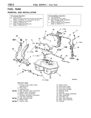
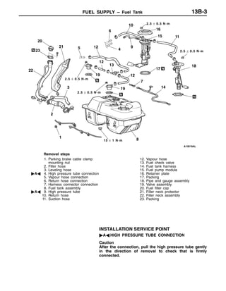
1) Steps for removing and installing the fuel tank, which involves disconnecting fuel lines and hoses, removing mounting nuts, and reconnecting lines post-installation.
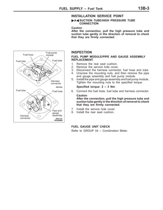
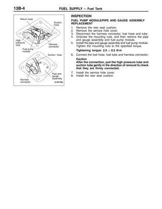
2) Inspection instructions for replacing the fuel pump module and pipe/gauge assembly, including disconnecting components, loosening nuts, reinstalling securely, and reconnecting.
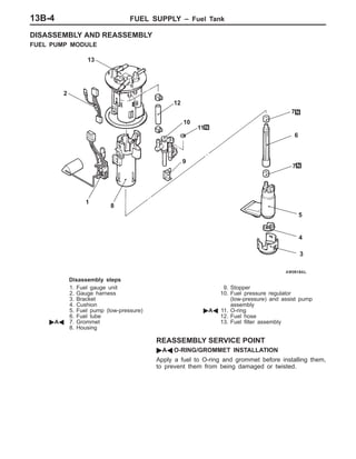
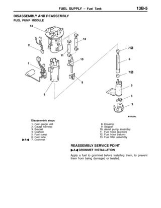
3) Disassembly steps for the fuel pump module and a service point about applying fuel to grommets during reassembly.


![[JSDC 2016] Codex: Conditional Modules Strike Back](https://cdn.slidesharecdn.com/ss_thumbnails/codex-conditionalmodulesstrikebackalexliujsdc2016-161023023432-thumbnail.jpg?width=640&height=640&fit=bounds)


