Download to read offline
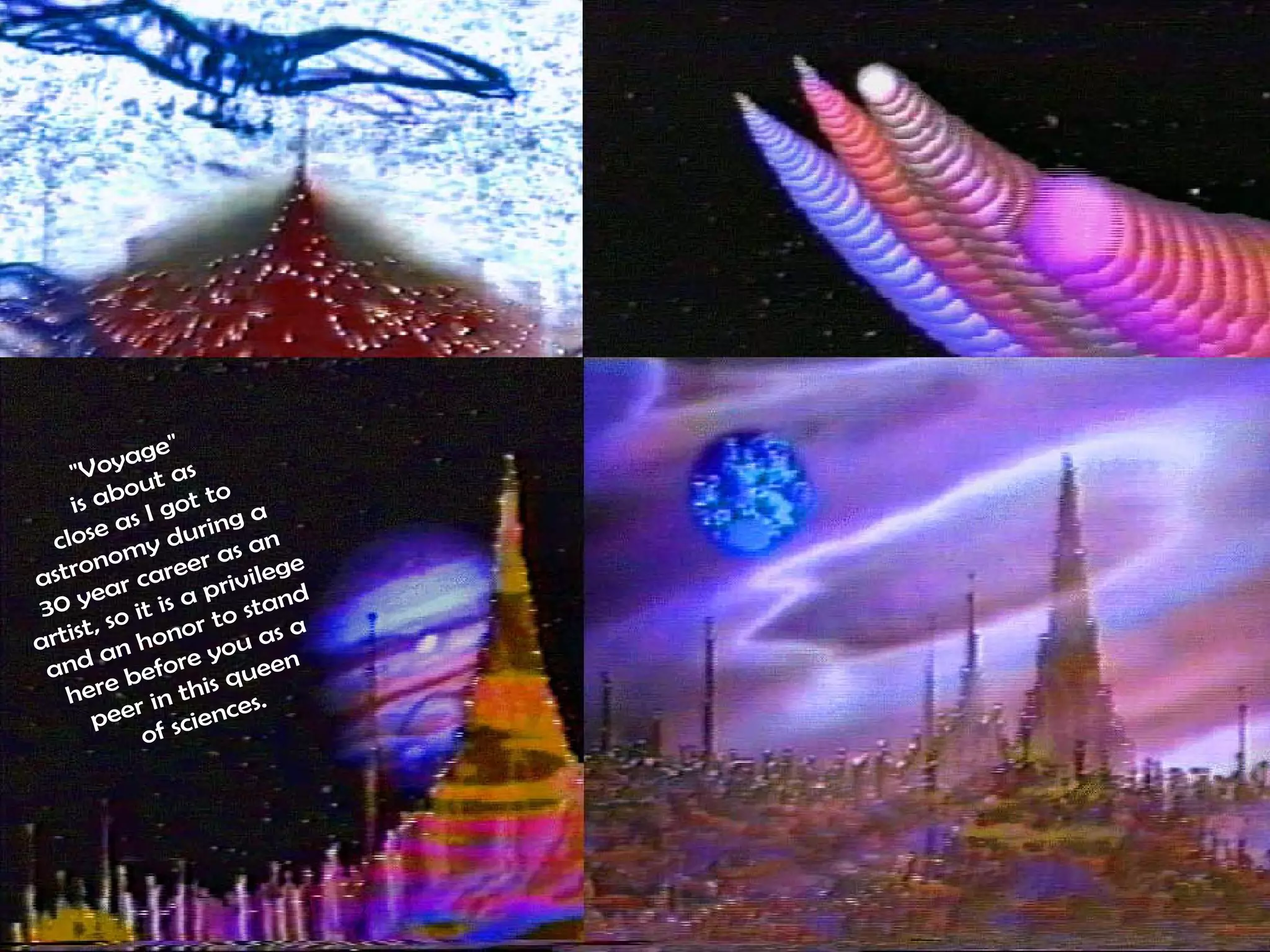
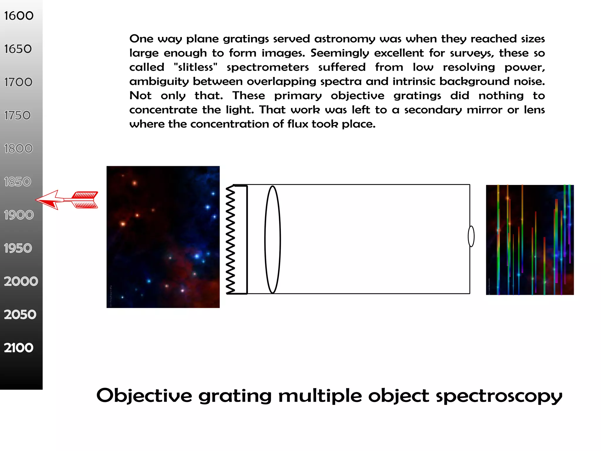
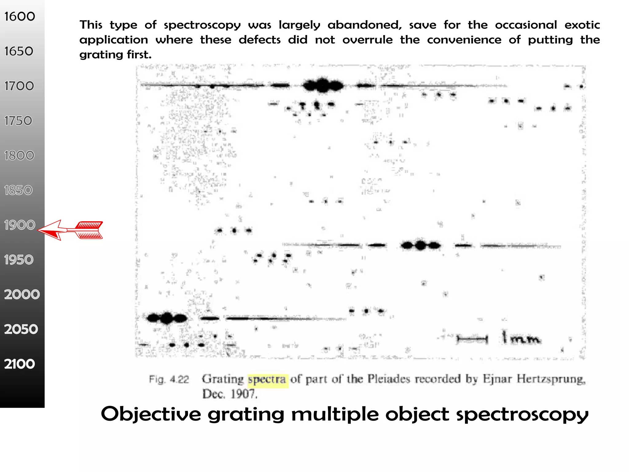
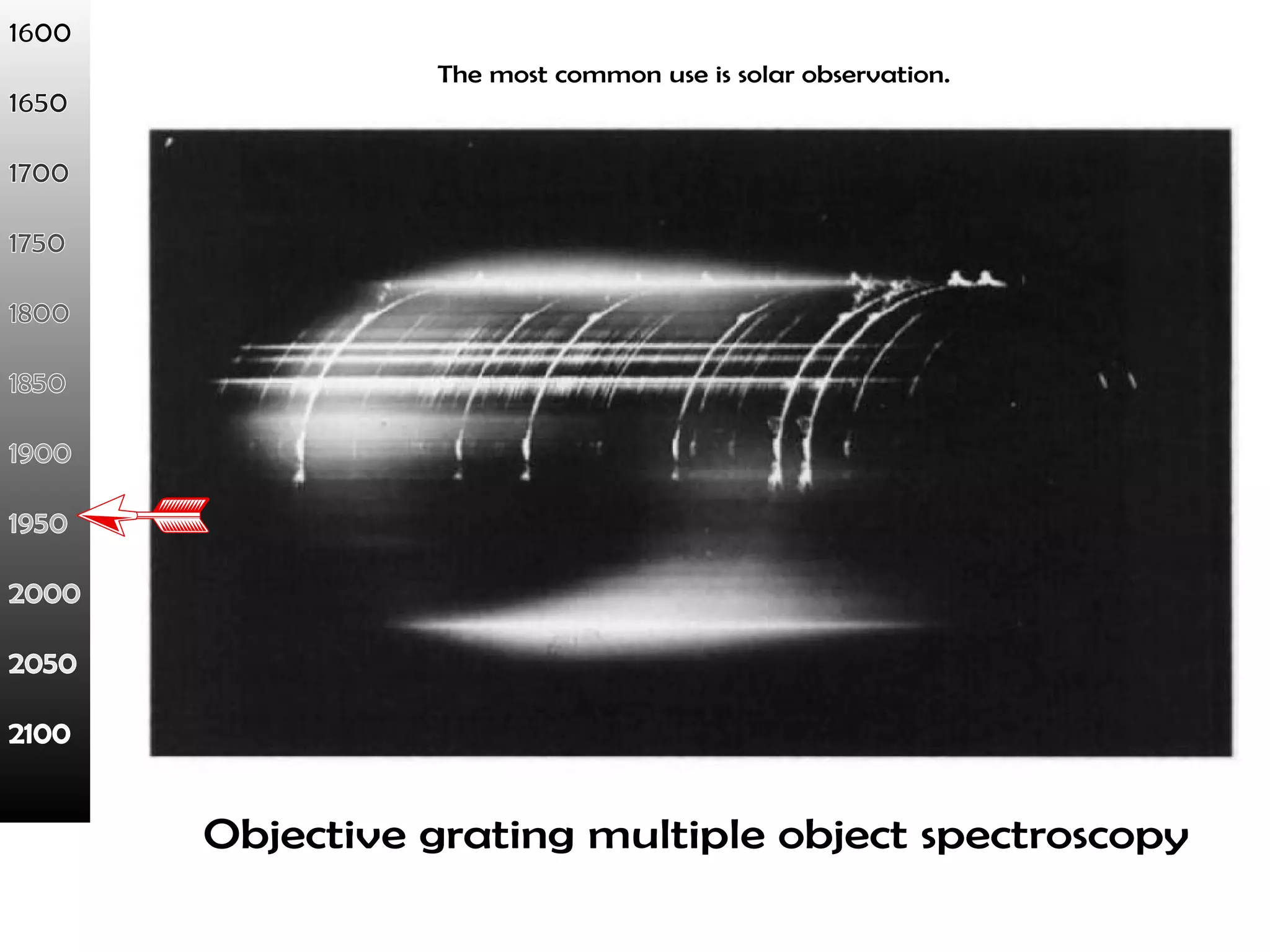
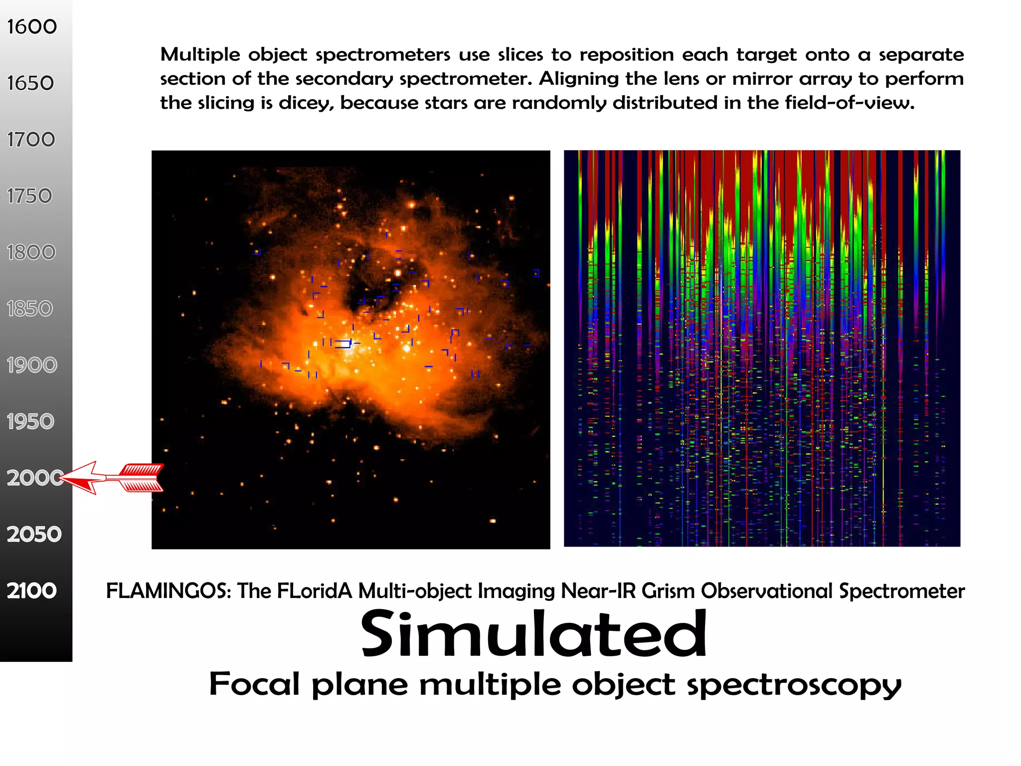
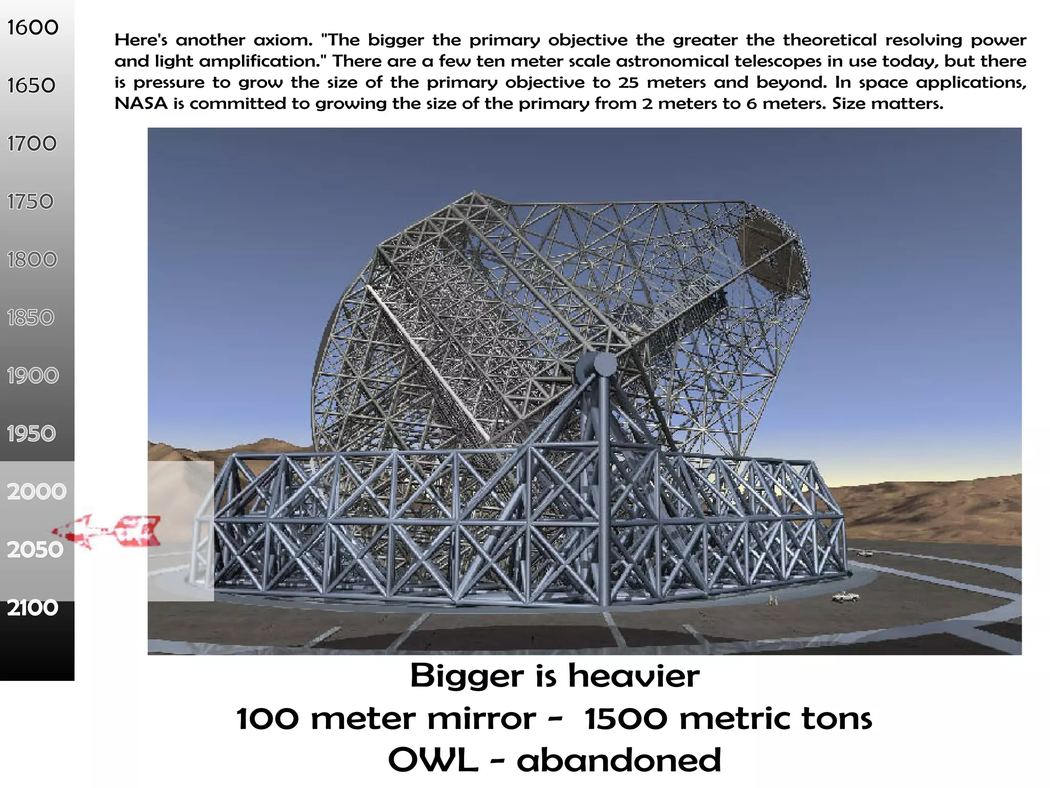
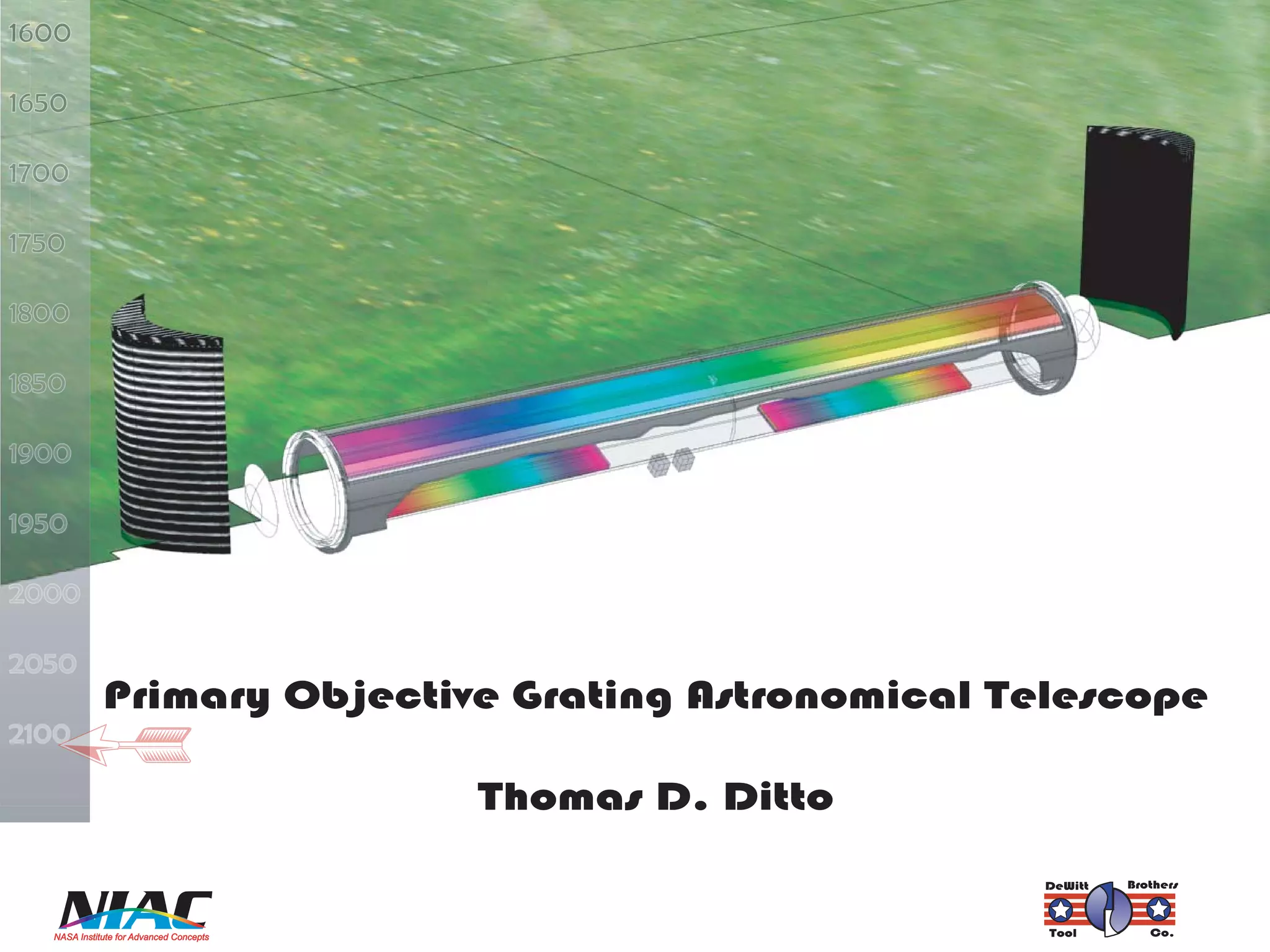
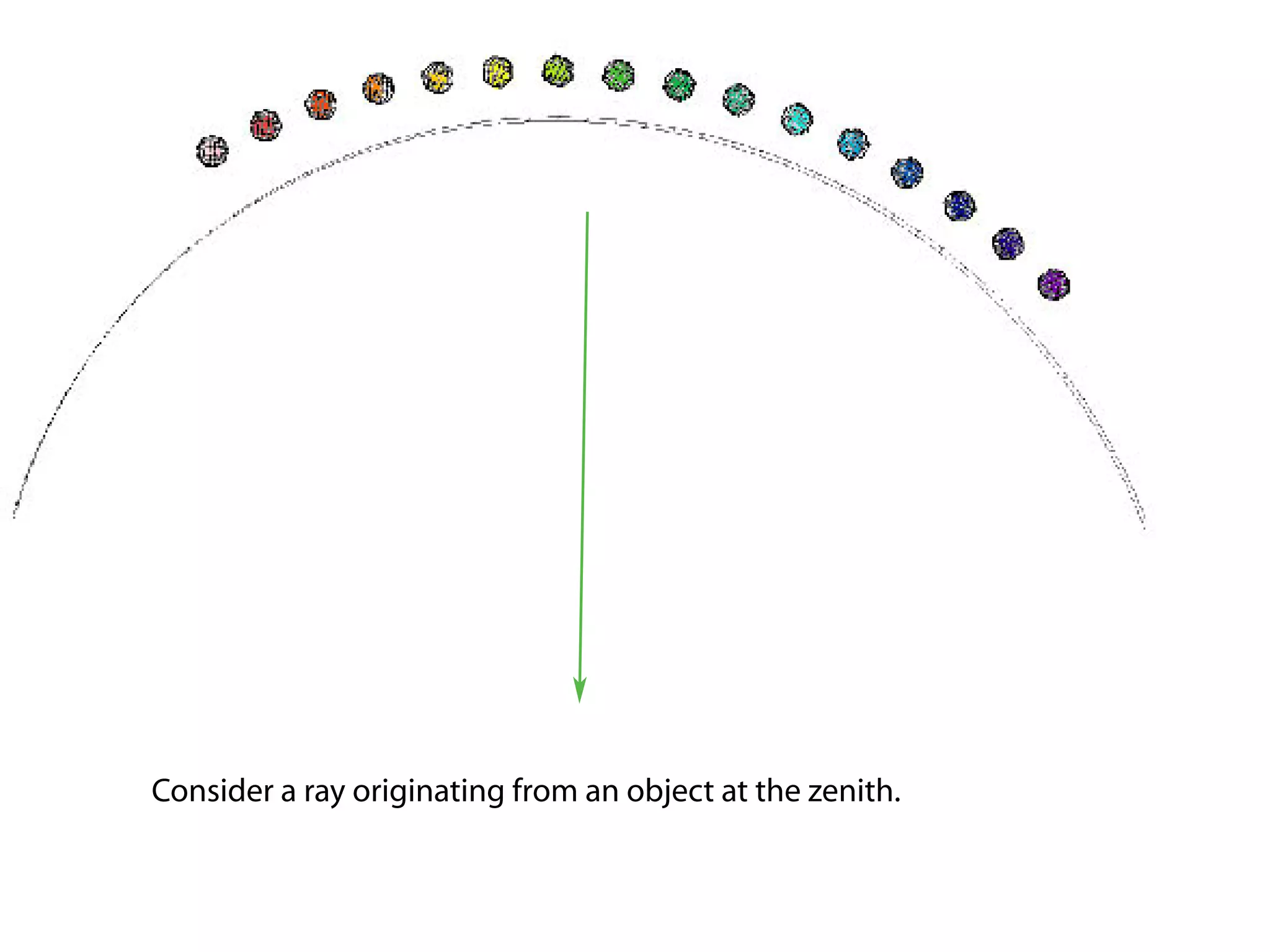
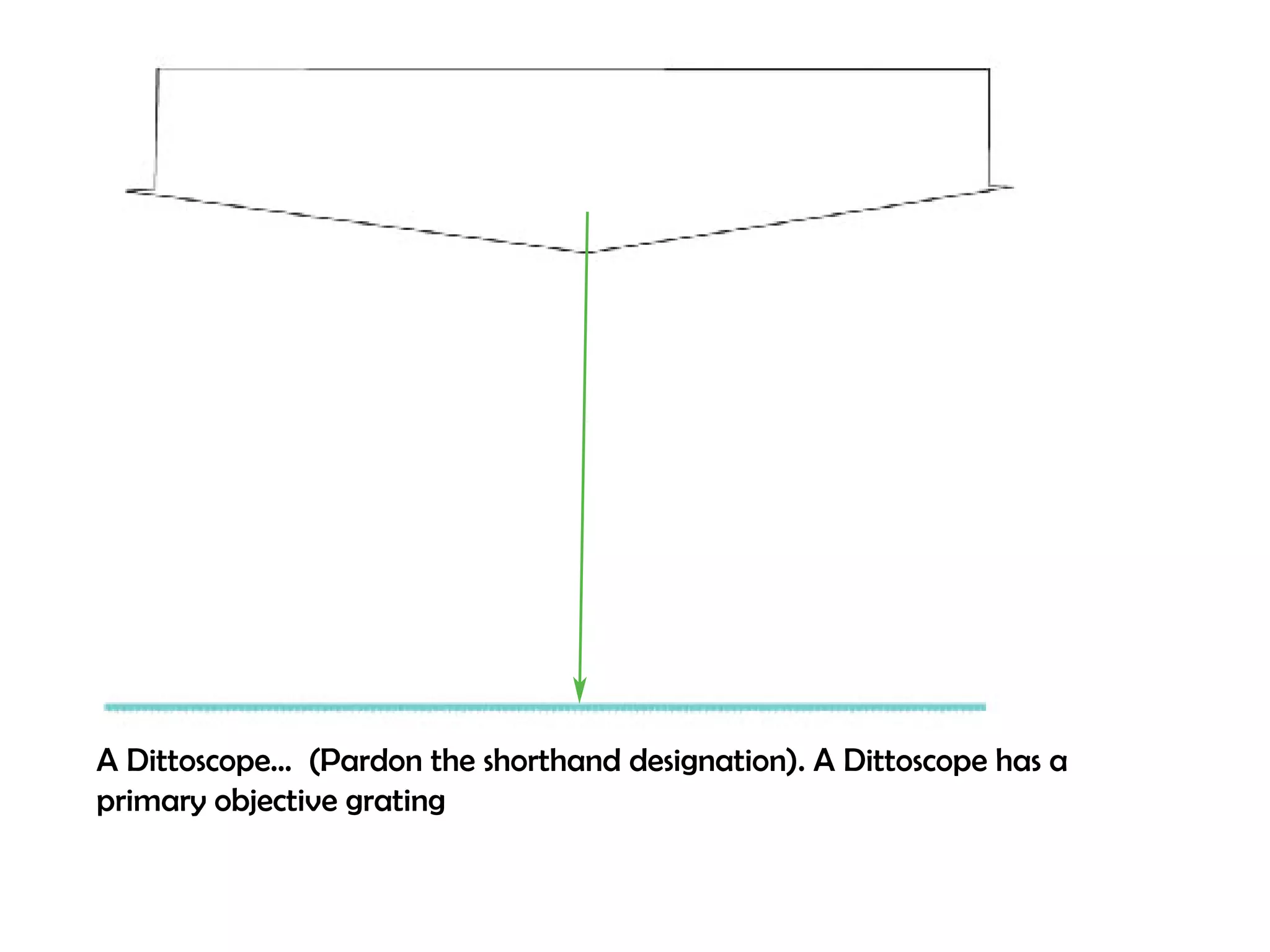
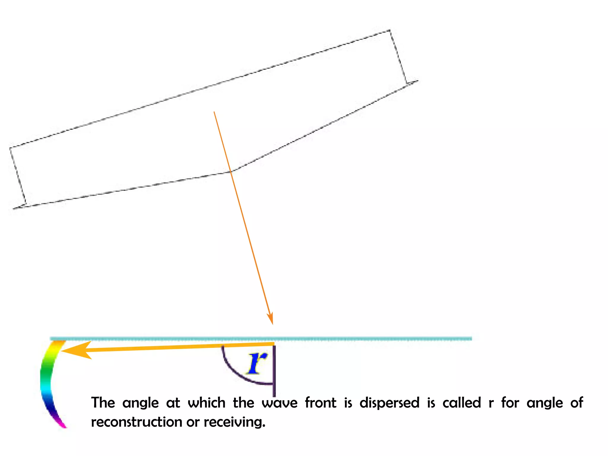
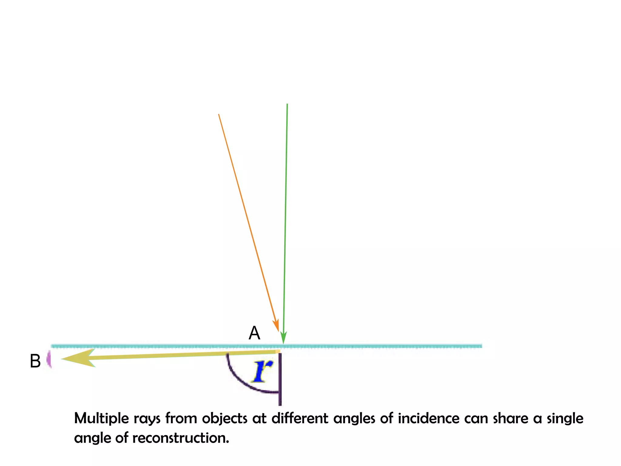
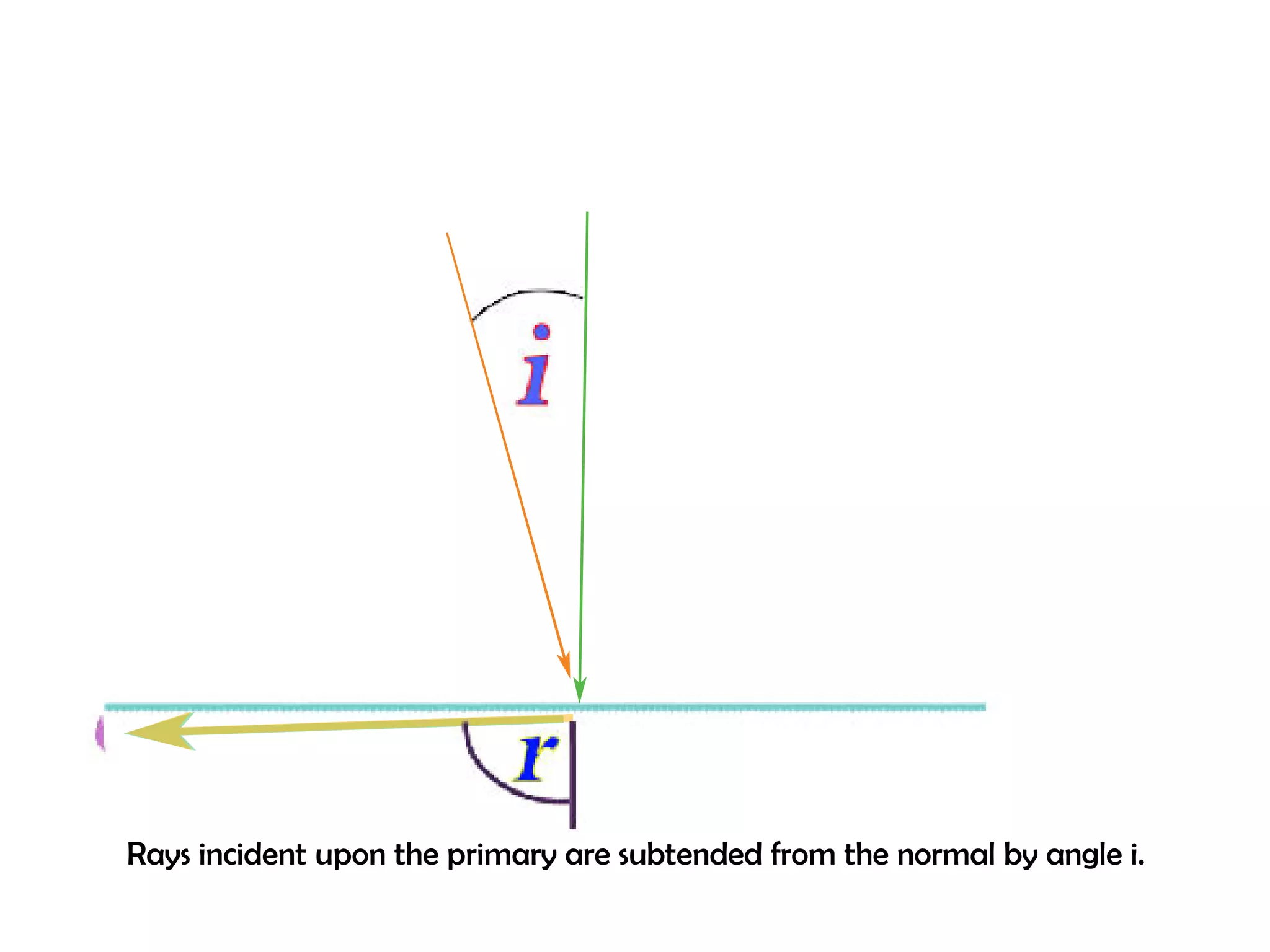
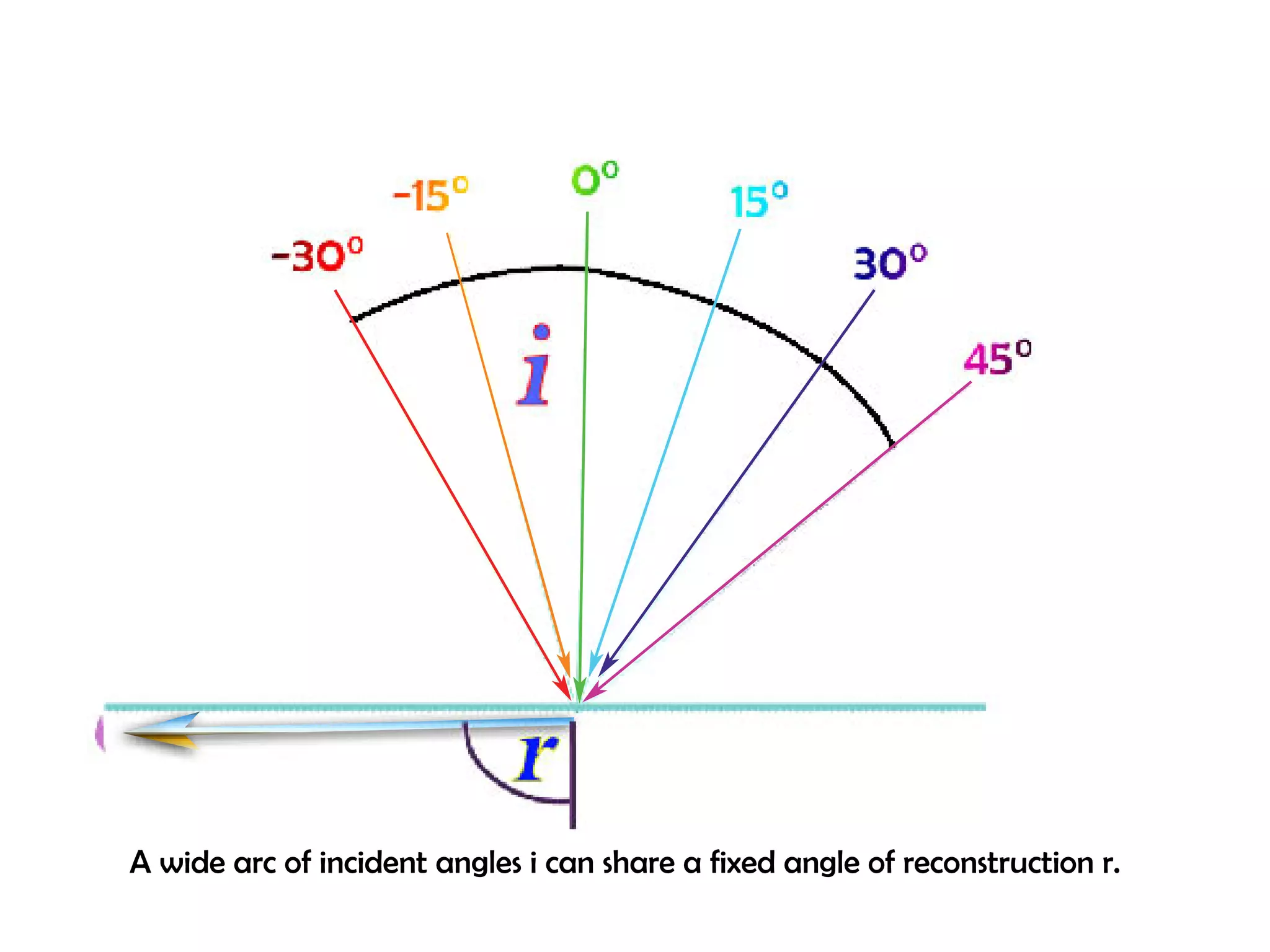
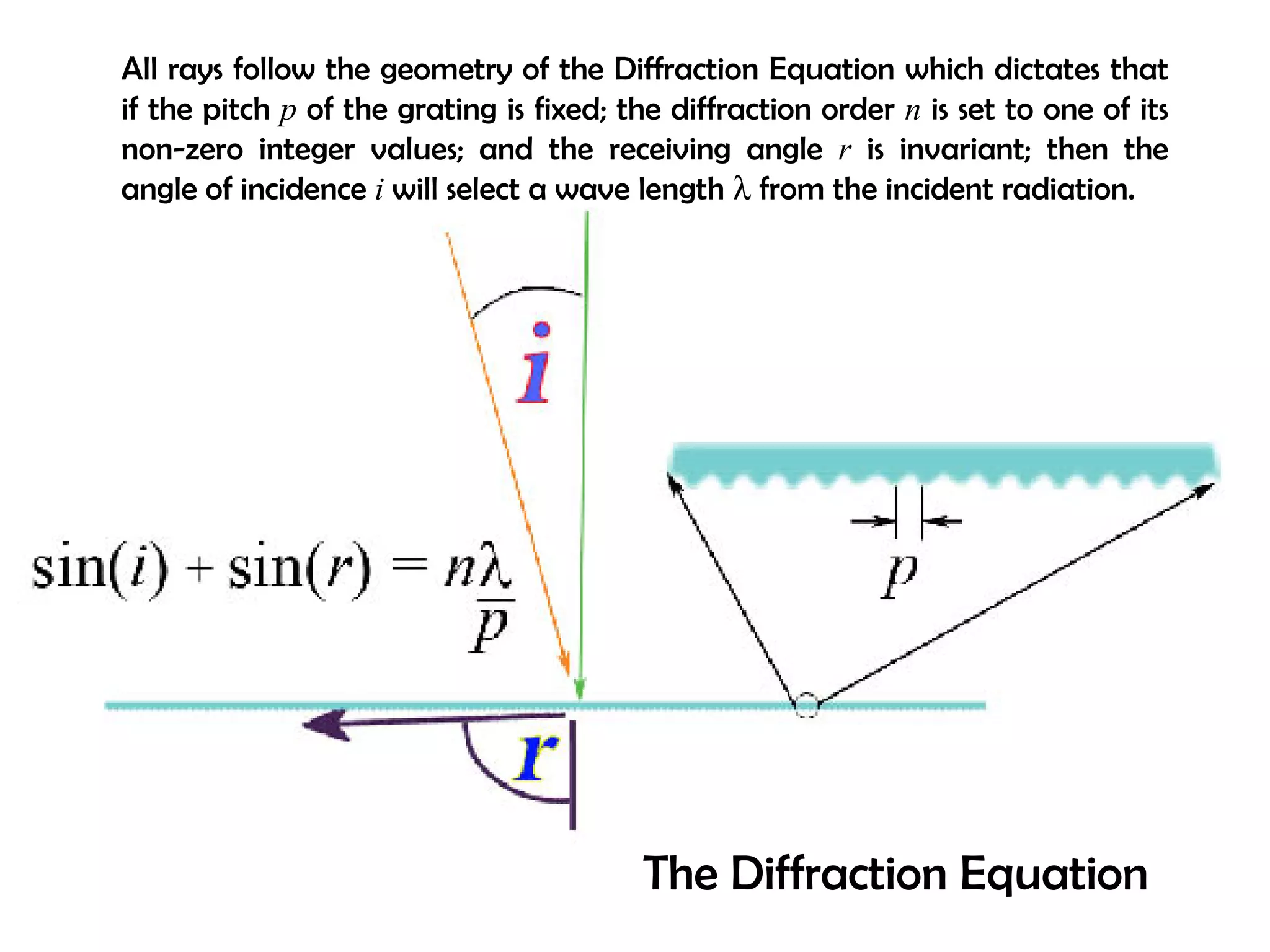
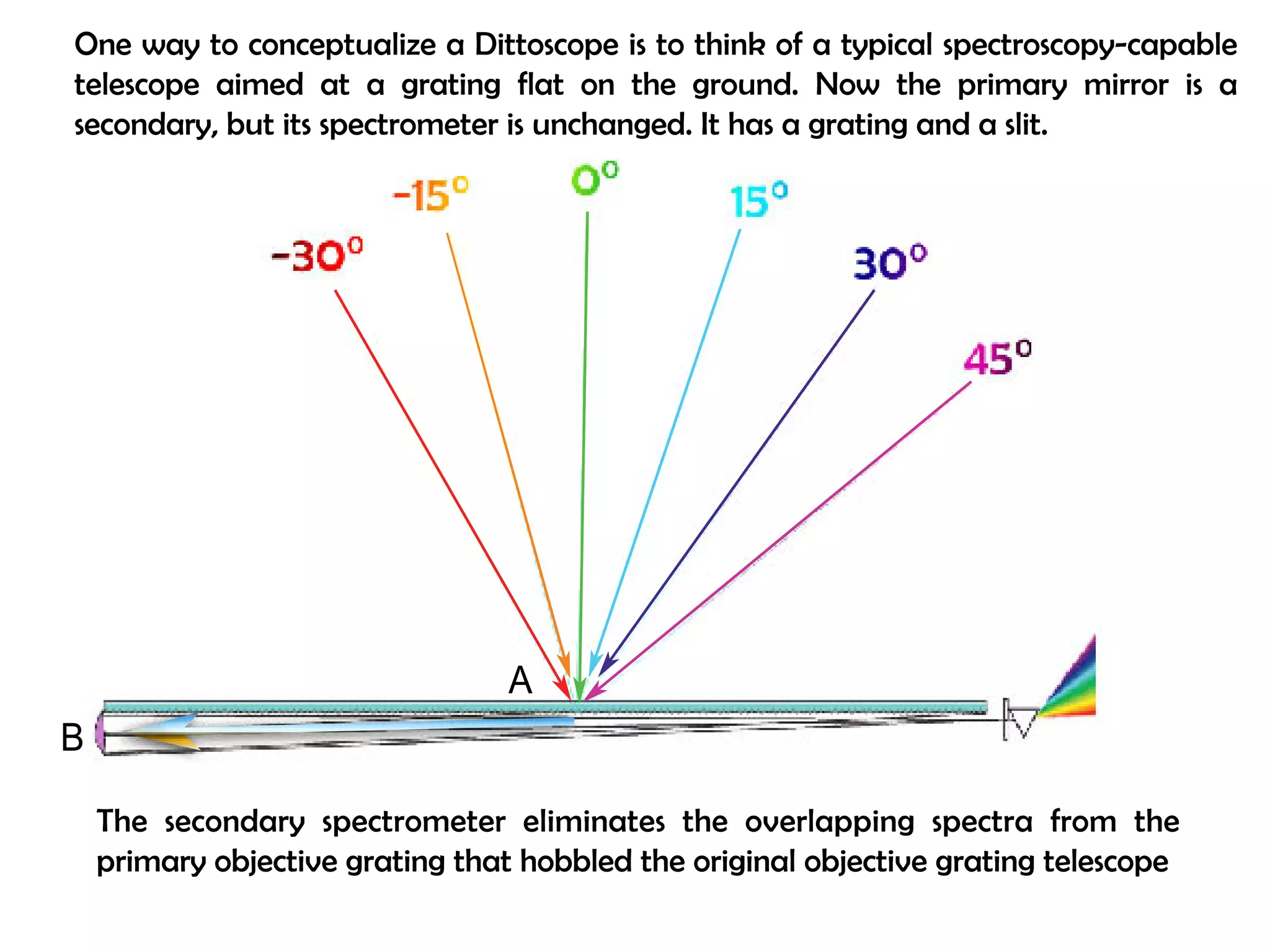
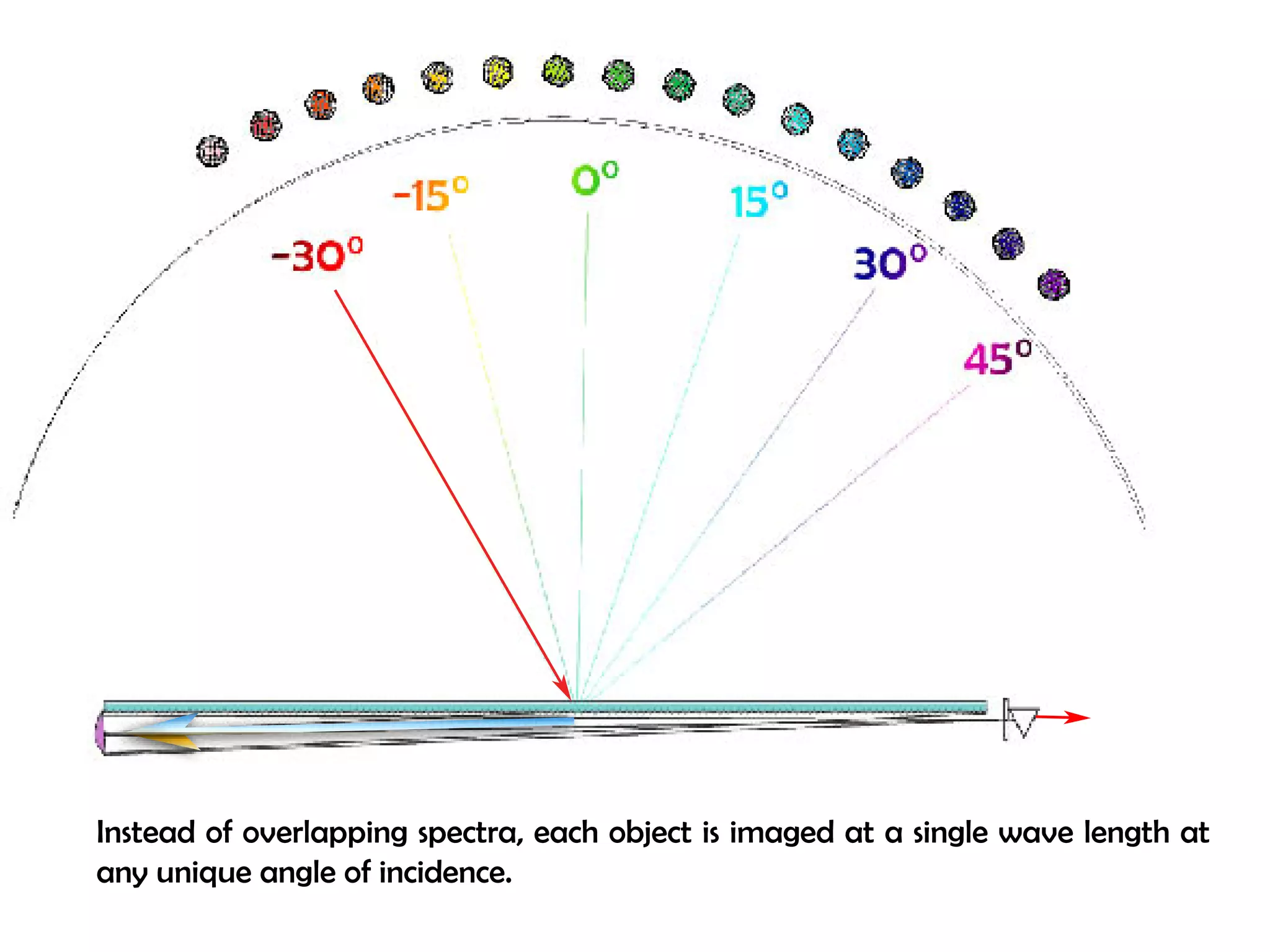
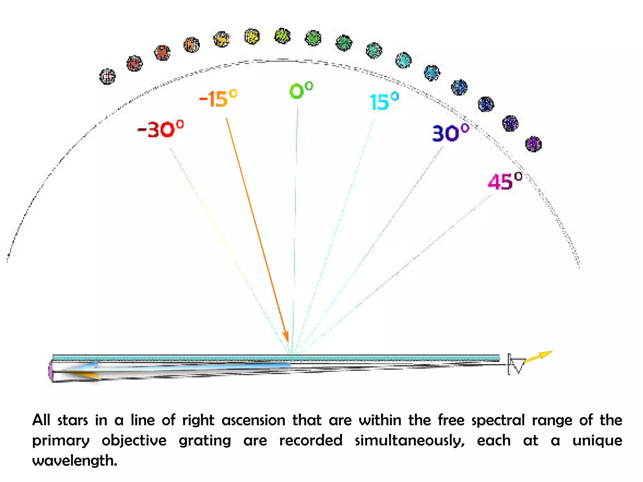
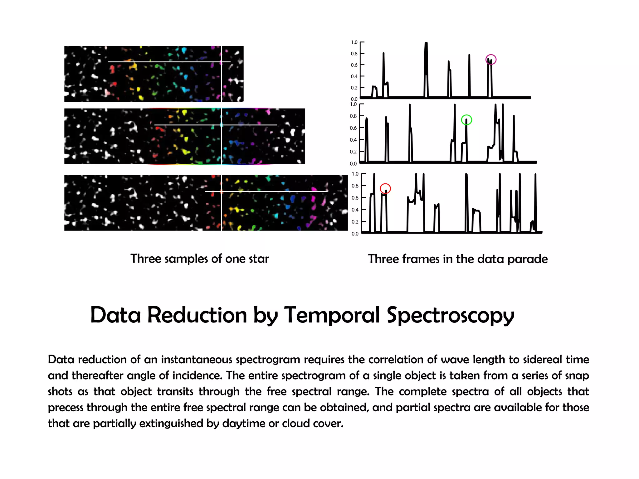
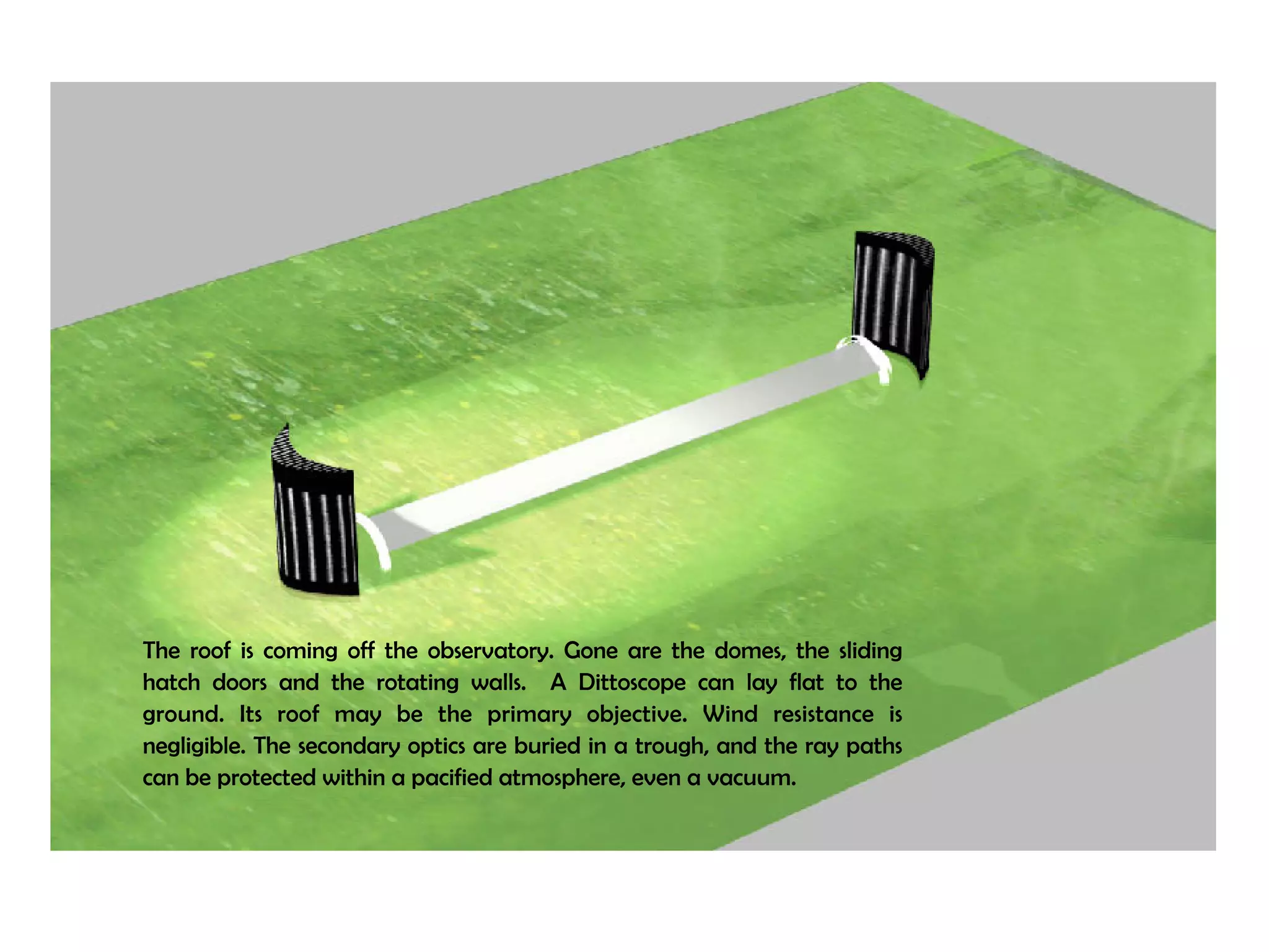
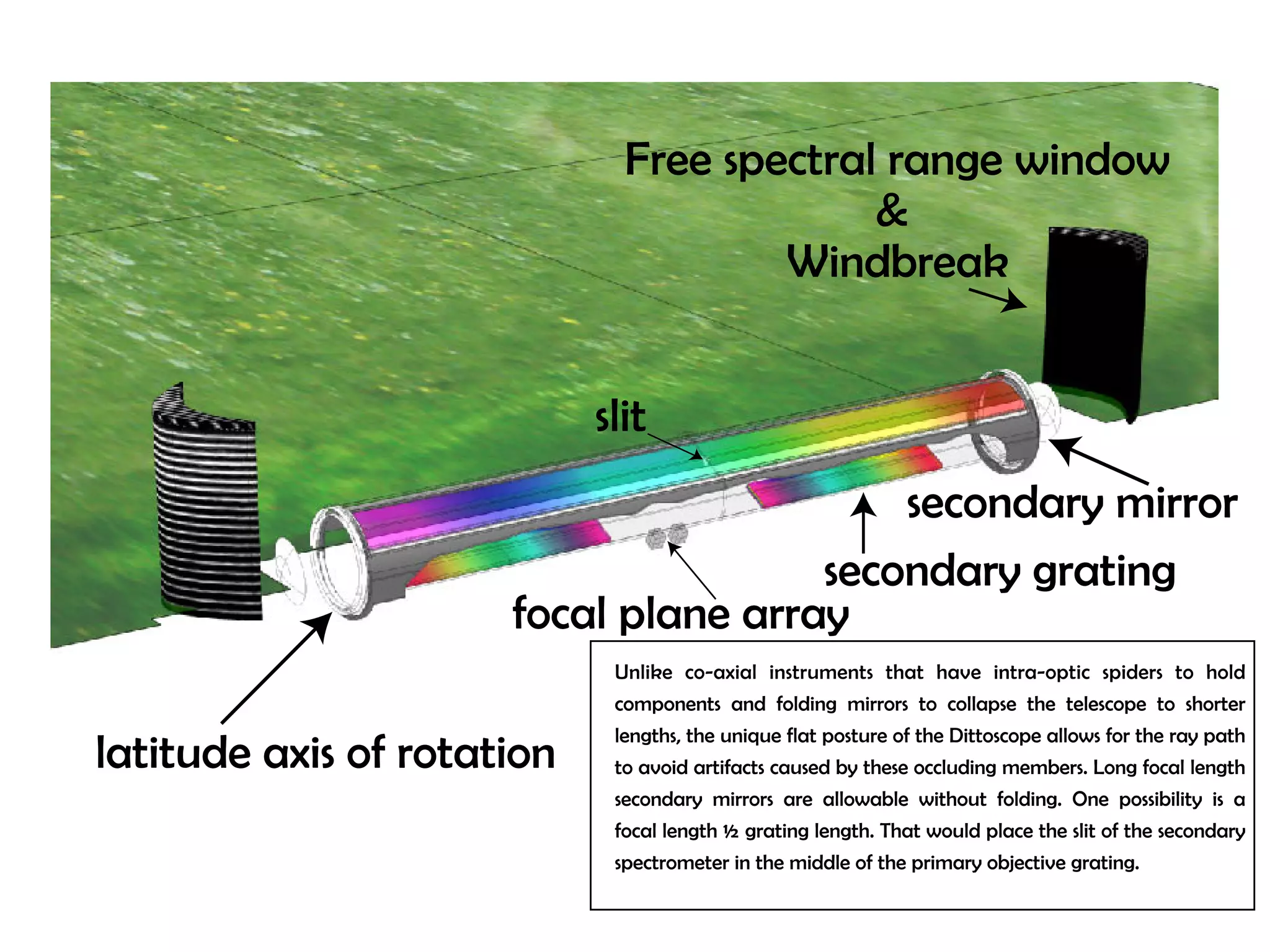
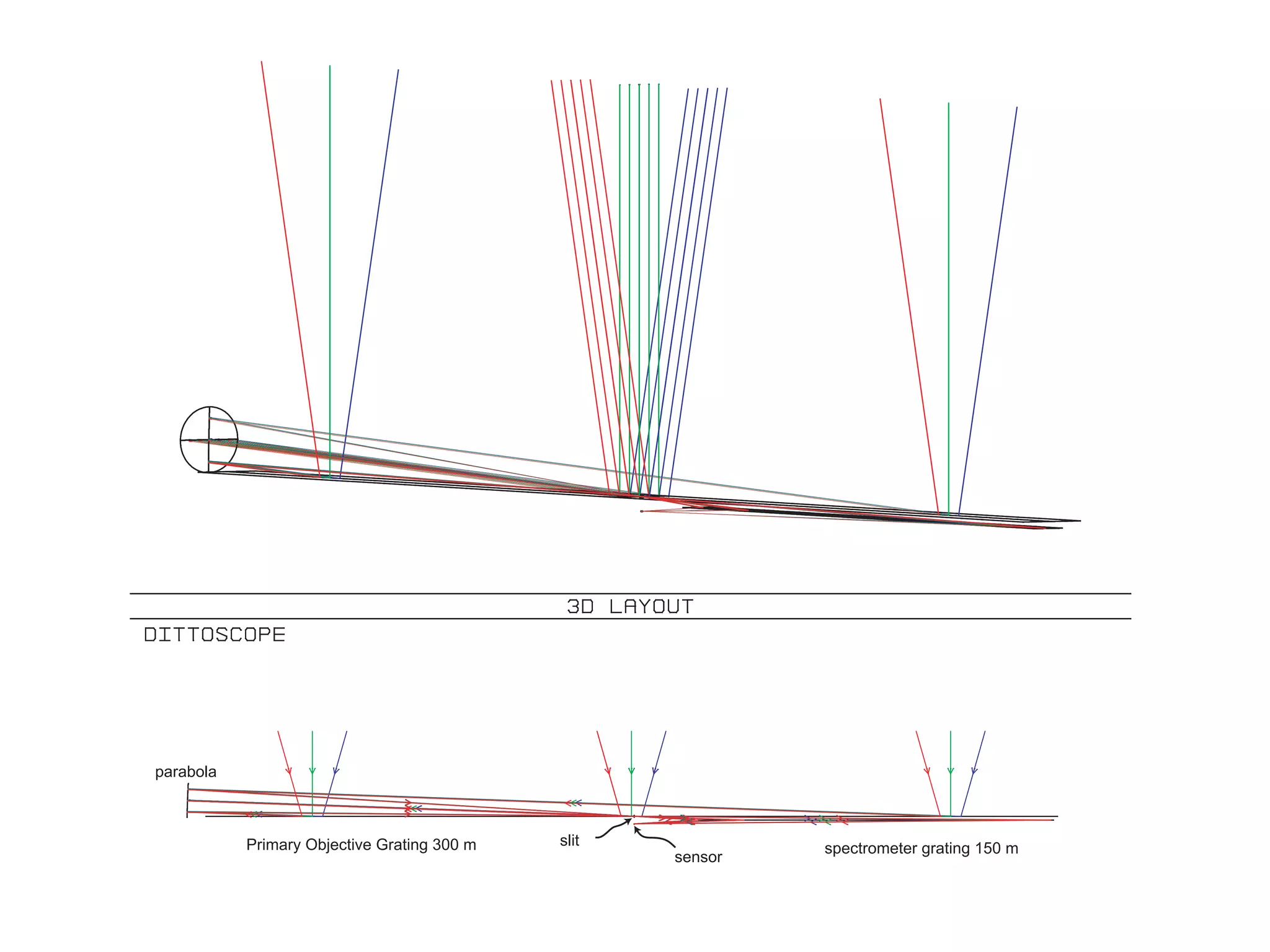
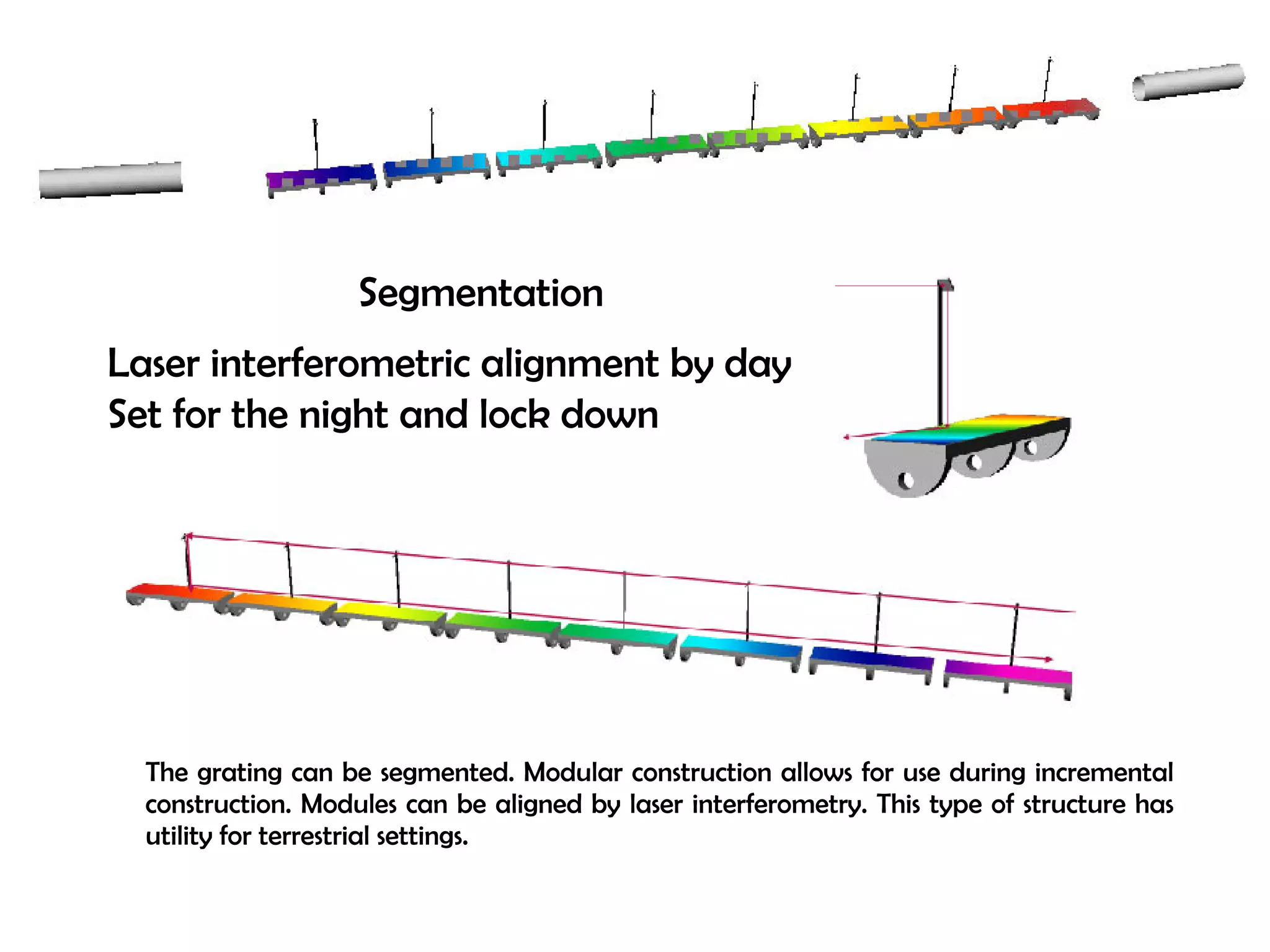
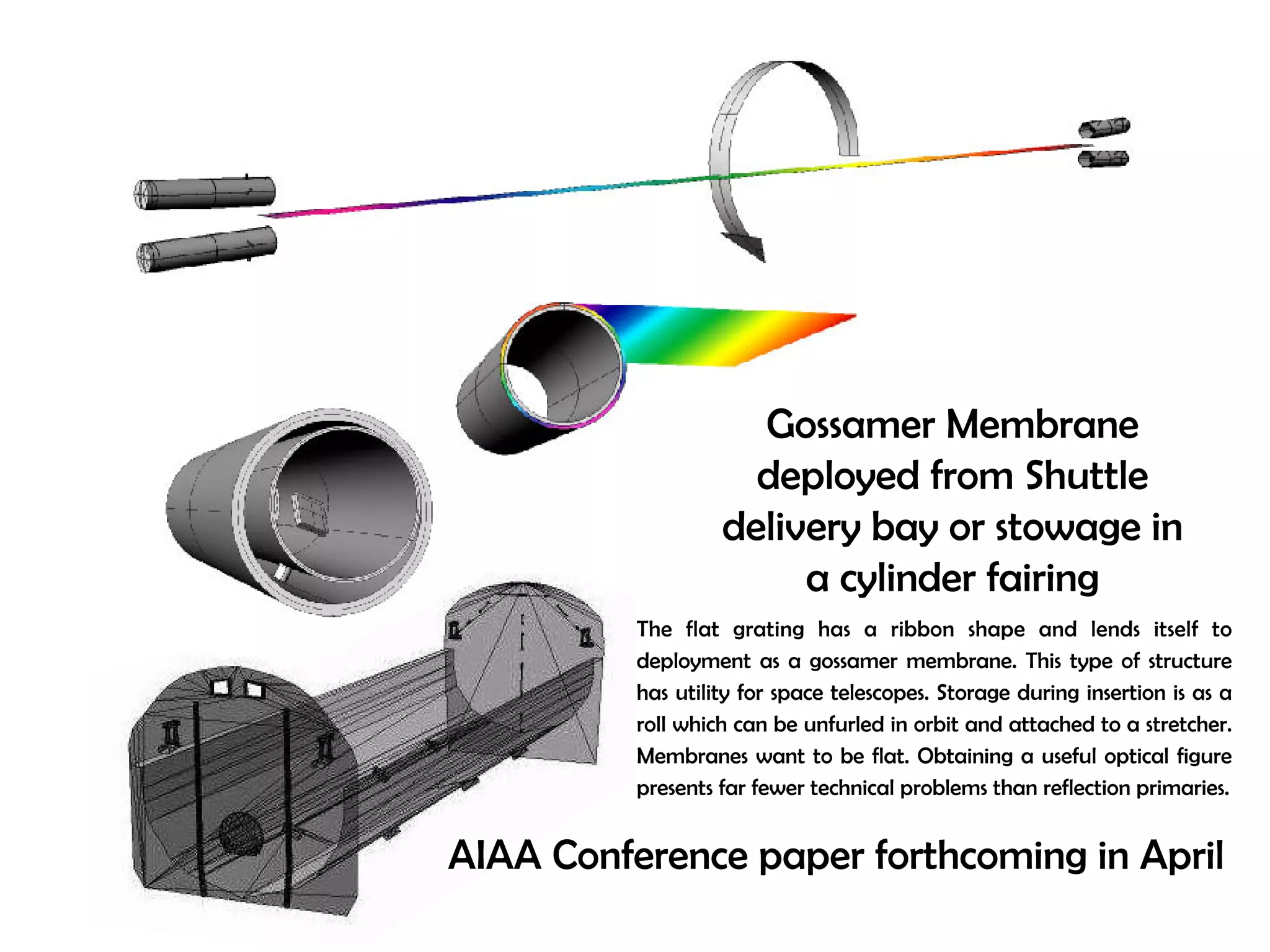
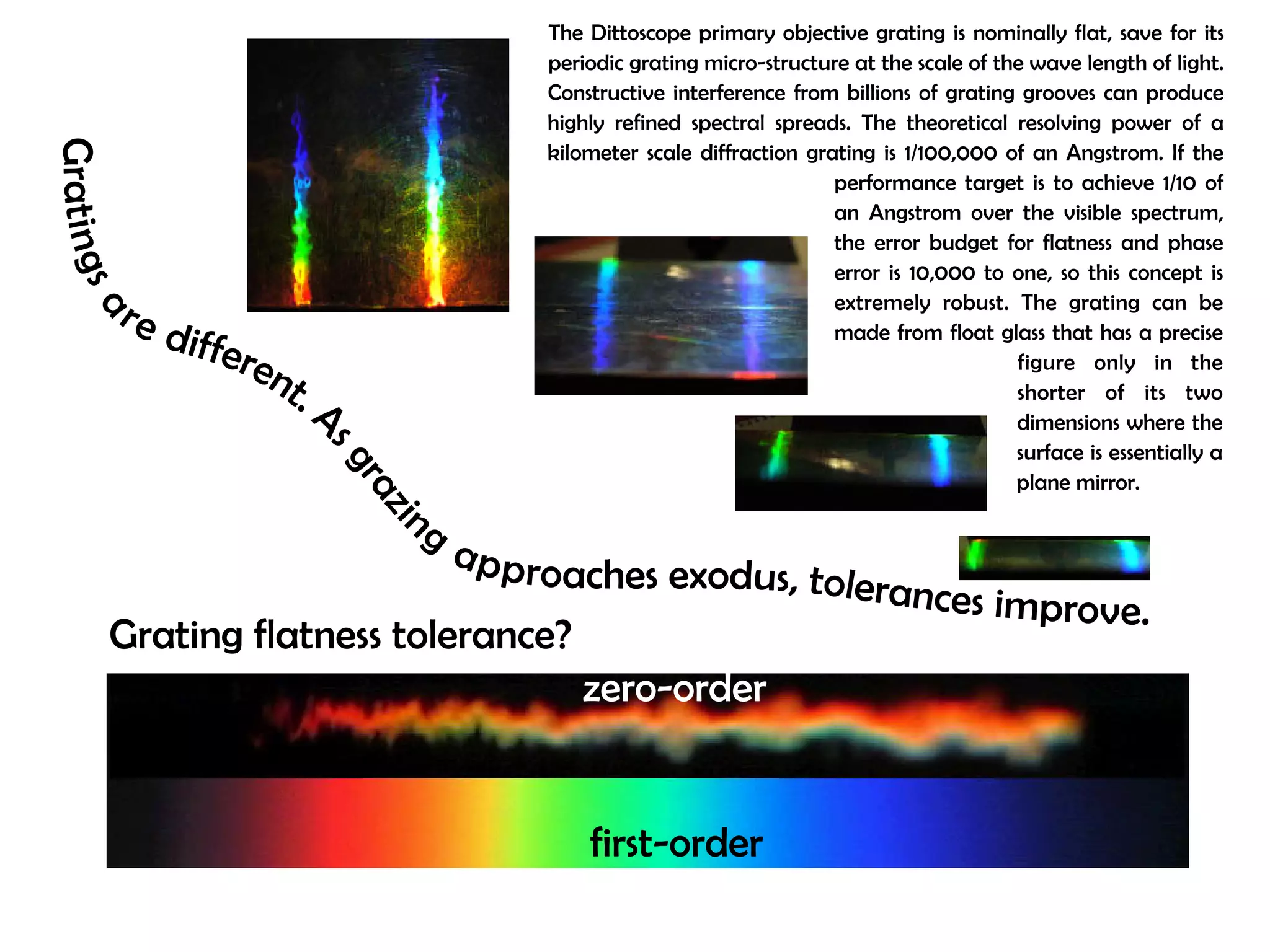
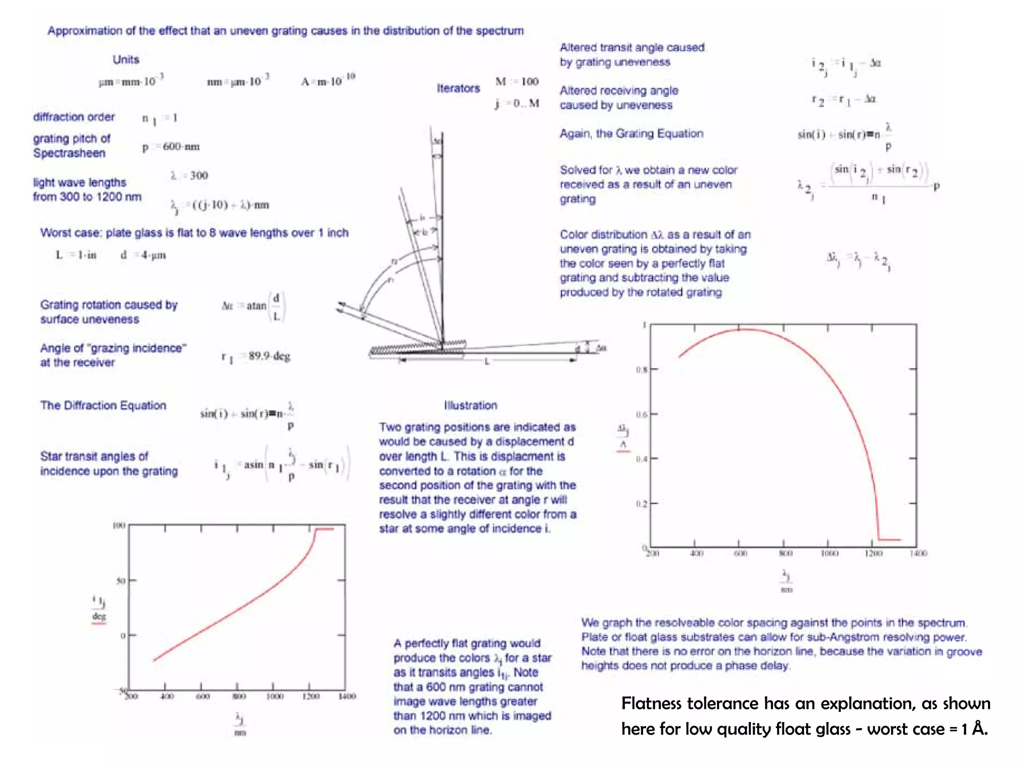
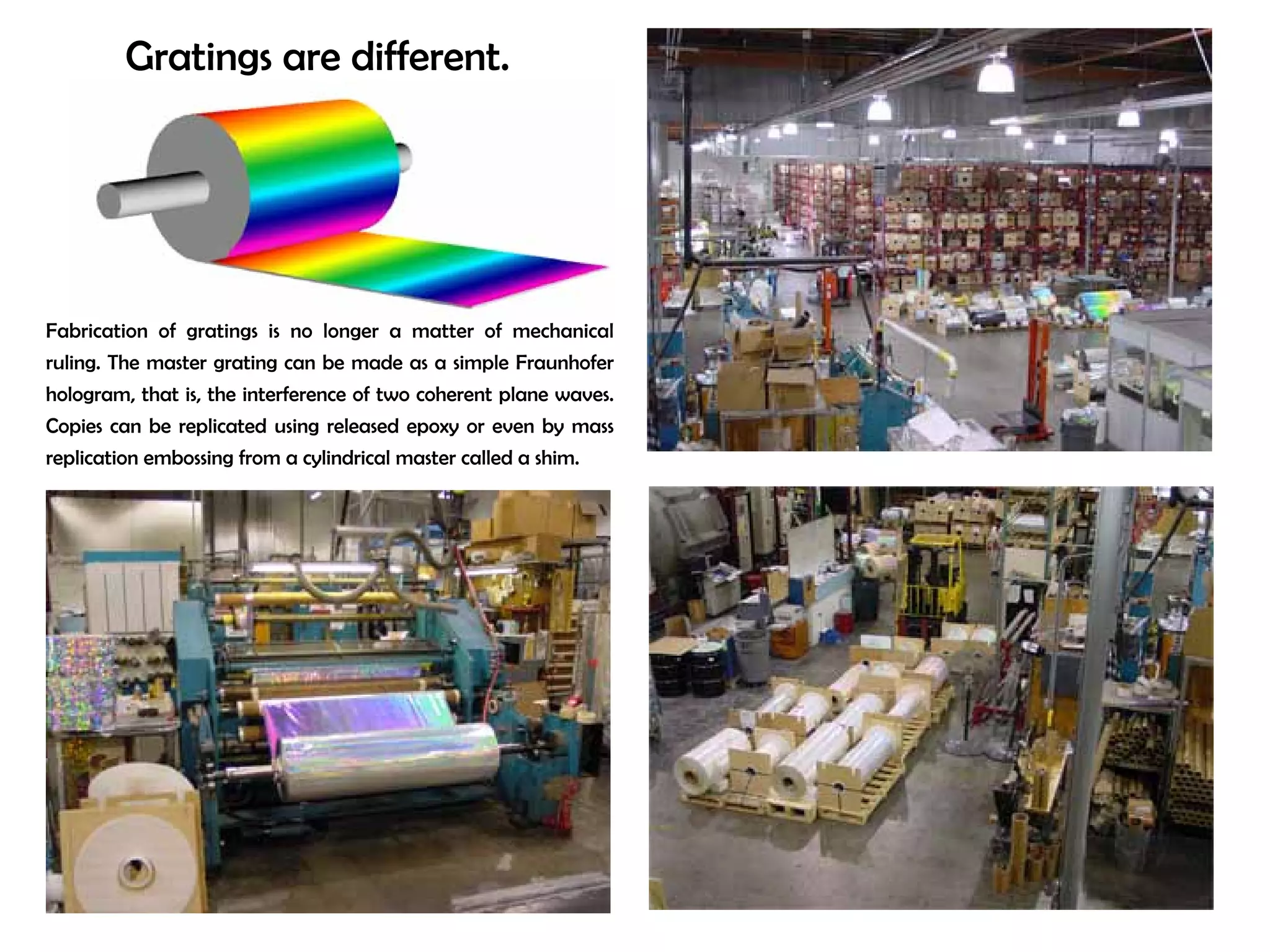
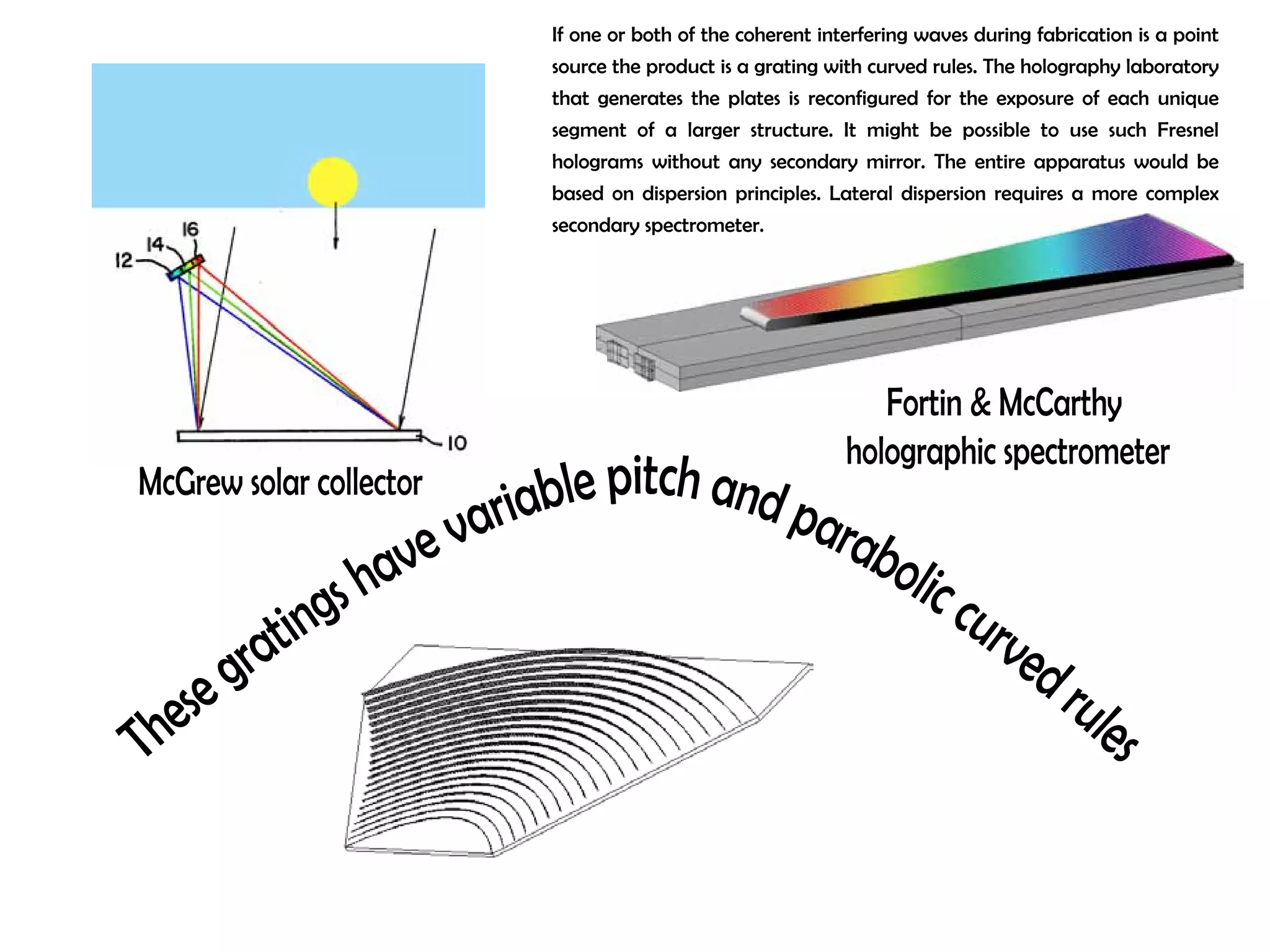
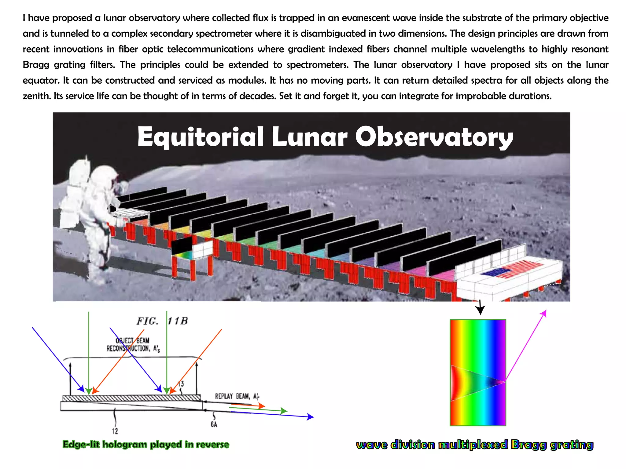
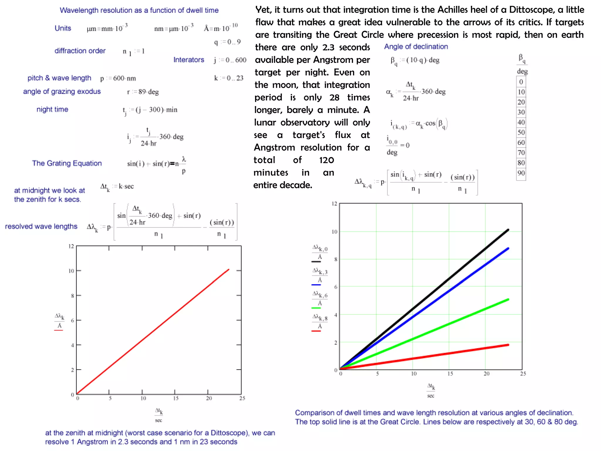
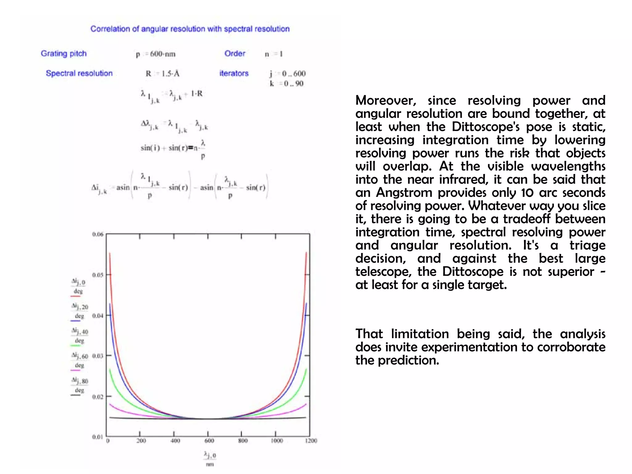
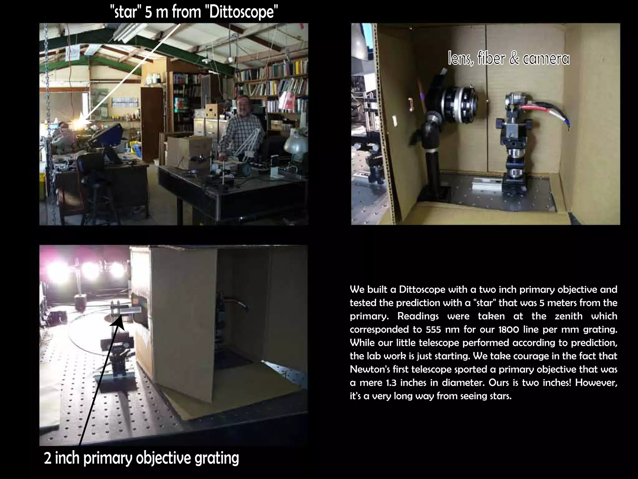
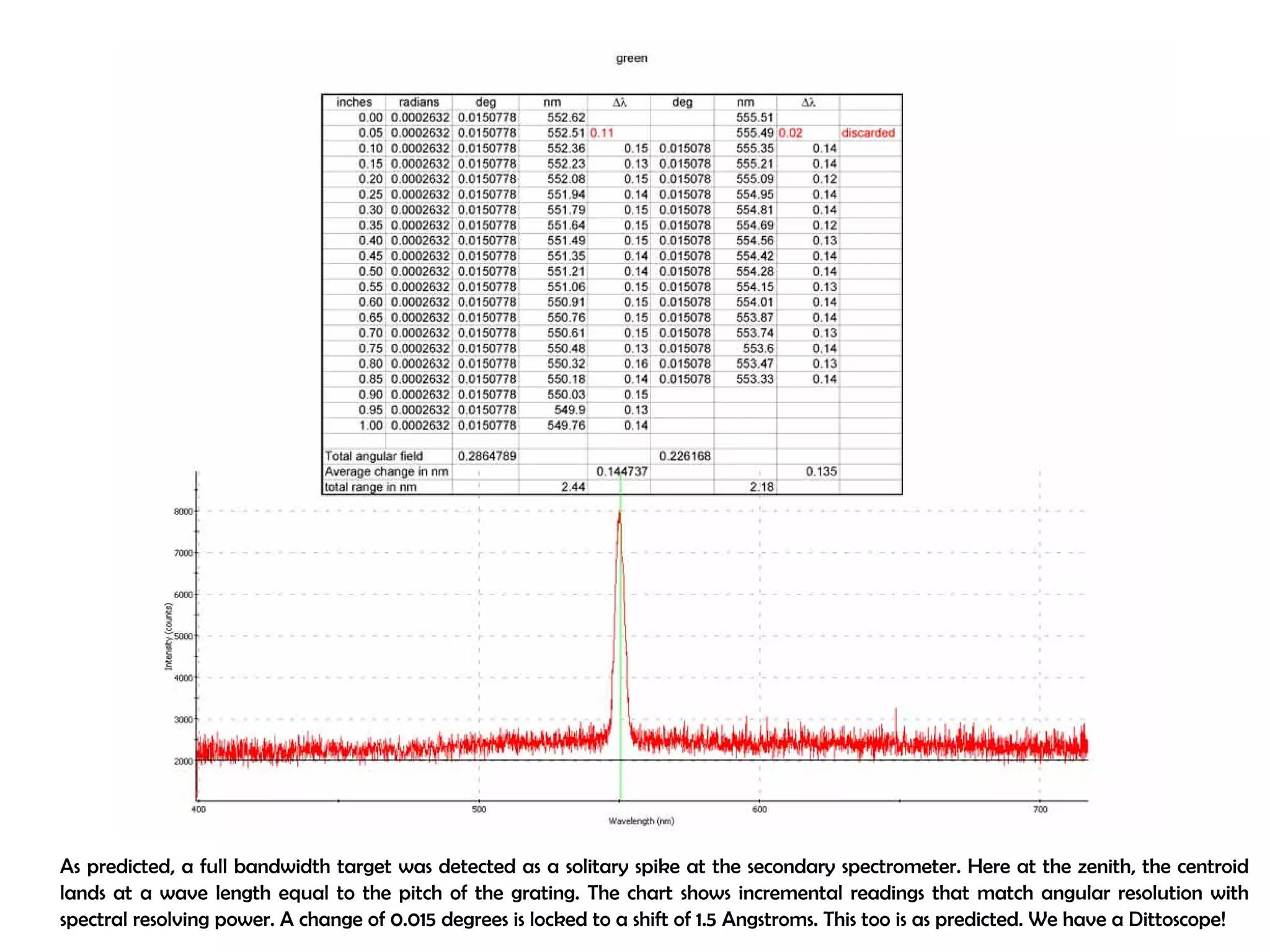
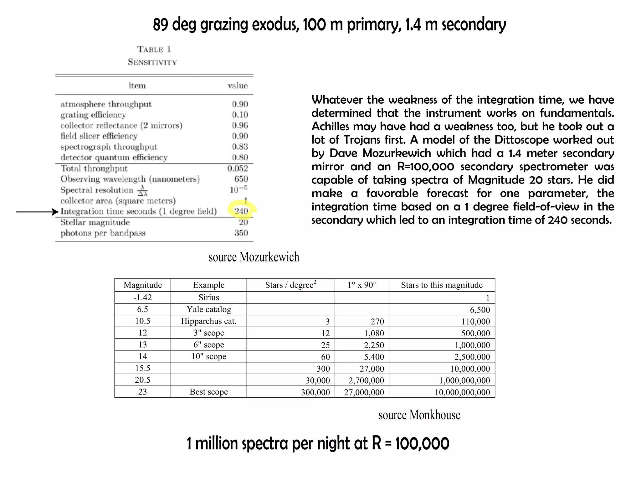
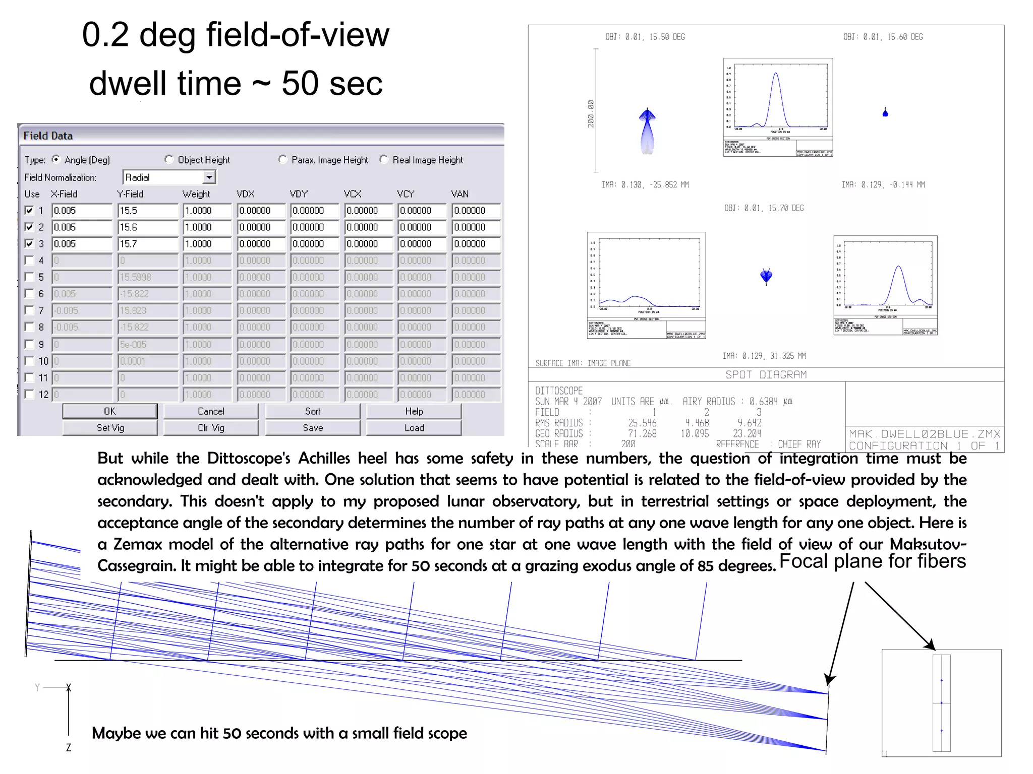

This document proposes a new type of astronomical telescope called a Dittoscope that uses a diffraction grating as its primary objective instead of a mirror or lens. It describes how the grating would disperse incoming light at grazing angles, allowing multiple sky objects to be imaged simultaneously at different wavelengths. Key advantages include no moving parts, large light collection area, and obtaining spectra for many objects at once without needing to target them individually. However, it notes a major limitation is that with the earth's rotation, each object's light is only dispersed at a given wavelength for a few seconds per night, limiting integration times.


![999 cash[2]](https://cdn.slidesharecdn.com/ss_thumbnails/lzsrjzmzqu2g6ytran2g-signature-3e49a9720aafd161ec5213fc5cb0fac76e0a38578f2089fb876ad1cc6de4bad4-poli-140825181335-phpapp02-thumbnail.jpg?width=640&height=640&fit=bounds)


![1200 cash[2]](https://cdn.slidesharecdn.com/ss_thumbnails/enxkjvufqc6h4ffmmmnz-signature-fabe374f978bfb273f92443e2c8243d3e294d623a7c677008fe136d7284f57a9-poli-140825181532-phpapp01-thumbnail.jpg?width=640&height=640&fit=bounds)


![[Company]대우증권 2008 01-03](https://cdn.slidesharecdn.com/ss_thumbnails/company2008-01-03-110120095408-phpapp02-thumbnail.jpg?width=640&height=640&fit=bounds)


![Wassersug richard[1]](https://cdn.slidesharecdn.com/ss_thumbnails/wassersugrichard1-140914105156-phpapp02-thumbnail.jpg?width=640&height=640&fit=bounds)


