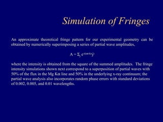
Download as PDF, PPTX

![δ
sin
B1=
θ
B2 = B1cos(2θ )
[ ( )] δ θ
Pathlength Tolerance Analysis at Grazing Incidence
δ θ 2 sin
OPD = B1− B2 = 1− cos 2 =
θ
sin
θ
δ λ
20sin
θ Β2 If OPD to be λ/10 then
( )
λ
θ θ
20sin cos
d Baseline
( )
θ
λ
20sin2
d focal
A1 A2
S1
S2
δ
A1 A2 in Phase Here
C
θ
θ
θ
Β1](https://image.slidesharecdn.com/xrayinterferometry-140914105203-phpapp02/85/Xray-interferometry-19-320.jpg)
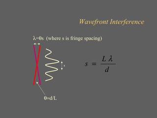
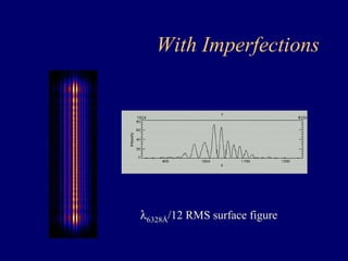
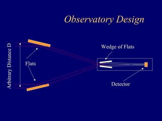
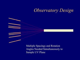
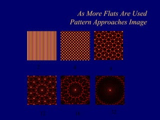
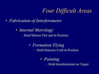
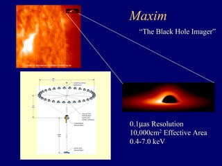
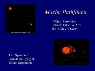
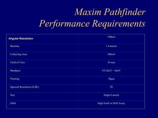
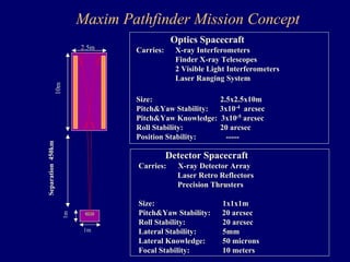
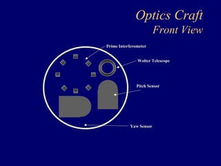
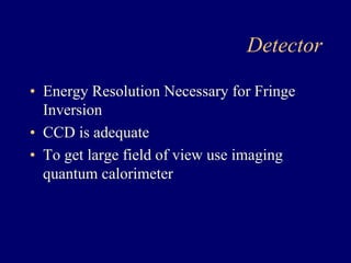
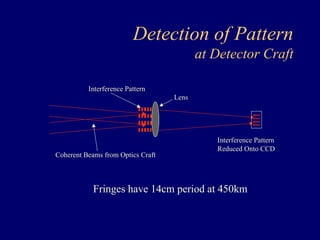
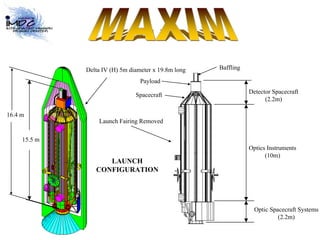
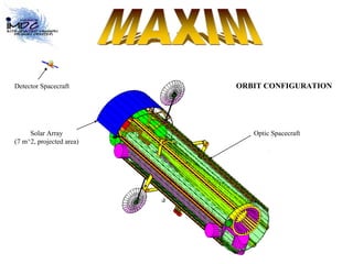
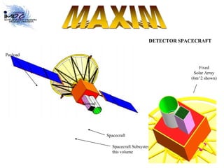
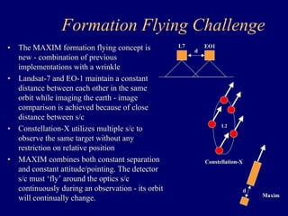

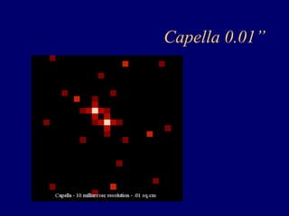
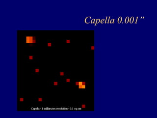
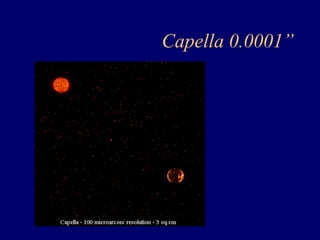
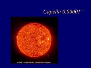
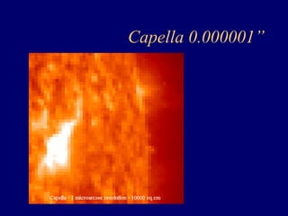
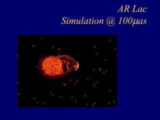
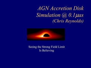
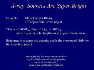
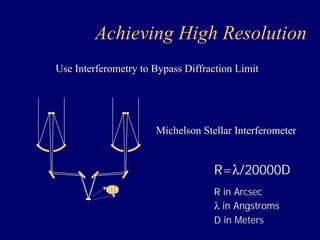
This document discusses the concept of an X-ray interferometer called MAXIM that could achieve micro-arcsecond resolution. It would consist of an optics spacecraft holding multiple flat mirrors in formation with a detector spacecraft to form interference patterns. The goal is to image phenomena like black hole accretion disks and supernovae with much higher resolution than current telescopes. A pathfinder mission is proposed with 100 microarcsecond resolution using two spacecraft separated by 1.4 meters as a technology demonstration.


![1138 schnopper[1]](https://cdn.slidesharecdn.com/ss_thumbnails/trqooqurqcw9tvydz38u-signature-fabe374f978bfb273f92443e2c8243d3e294d623a7c677008fe136d7284f57a9-poli-140825181533-phpapp01-thumbnail.jpg?width=640&height=640&fit=bounds)


![1207 angel[1]](https://cdn.slidesharecdn.com/ss_thumbnails/0dyqjbhorsiejdf2iide-signature-fabe374f978bfb273f92443e2c8243d3e294d623a7c677008fe136d7284f57a9-poli-140825181532-phpapp02-thumbnail.jpg?width=640&height=640&fit=bounds)


![999 cash[2]](https://cdn.slidesharecdn.com/ss_thumbnails/lzsrjzmzqu2g6ytran2g-signature-3e49a9720aafd161ec5213fc5cb0fac76e0a38578f2089fb876ad1cc6de4bad4-poli-140825181335-phpapp02-thumbnail.jpg?width=640&height=640&fit=bounds)


![Wassersug richard[1]](https://cdn.slidesharecdn.com/ss_thumbnails/wassersugrichard1-140914105156-phpapp02-thumbnail.jpg?width=640&height=640&fit=bounds)


