Downloaded 194 times

![Background
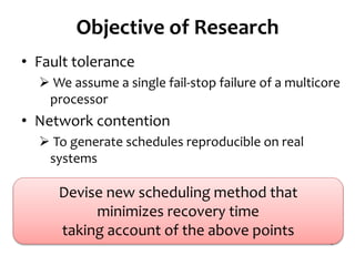
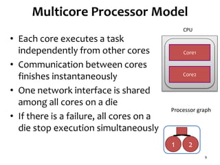
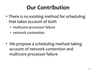
• Multicore processors
Almost all processors designed recently are
multicore processors
• Computing cluster consisting of 1800 nodes
experiences about 1000 failures[1]
in the first year after deployment
[1] Google spotlights data center inner workings
cnet.com article on May 30, 2008](https://image.slidesharecdn.com/120516ccgrid-120515132409-phpapp01/85/Slides-Task-scheduling-algorithm-for-multicore-processor-system-for-minimizing-recovery-time-in-case-of-single-node-fault-2-320.jpg)
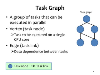
![Network Contention Model
• Communication delay
If processor link is occupied by another
communication
• We use existing network contention
model[2]
8
3
31
32
Contention 321
Processor graph
Task graph
[2] O. Sinnen and L.A. Sousa, “Communication Contention in
Task Scheduling,“ IEEE Trans. Parallel and Distributed Systems,
vol. 16, no. 6, pp. 503-515, 2005.](https://image.slidesharecdn.com/120516ccgrid-120515132409-phpapp01/85/Slides-Task-scheduling-algorithm-for-multicore-processor-system-for-minimizing-recovery-time-in-case-of-single-node-fault-8-320.jpg)
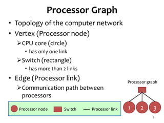
![Related Work (1/2)
• Checkpointing [3]
Node state is saved in each node
Backup node is allocated
Recover processing results from saved state
Multicore is not considered
Network contention is not considered
12
[3] Y. Gu, Z. Zhang, F. Ye, H. Yang, M. Kim, H. Lei, and Z. Liu. An empirical study of high
availability in stream processing systems. In Middleware ’09: the 10th
ACM/IFIP/USENIX International Conference on Middleware (Industrial Track), 2009.
1
2
3
4
Input
Queue
Output
Queue
Secondary
Primary
Backup](https://image.slidesharecdn.com/120516ccgrid-120515132409-phpapp01/85/Slides-Task-scheduling-algorithm-for-multicore-processor-system-for-minimizing-recovery-time-in-case-of-single-node-fault-12-320.jpg)
![Related Work (2/2)
• Task scheduling method[5] in which
Multiple task graph templates are prepared
beforehand,
Processors are assigned according to the templates
• This method is suitable for highly loaded
systems
[5] Wolf, J., et al.: SODA: An Optimizing Scheduler for Large-
Scale Stream-Based Distributed Computer Systems. In: ACM
Middleware (2008)](https://image.slidesharecdn.com/120516ccgrid-120515132409-phpapp01/85/Slides-Task-scheduling-algorithm-for-multicore-processor-system-for-minimizing-recovery-time-in-case-of-single-node-fault-13-320.jpg)
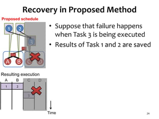
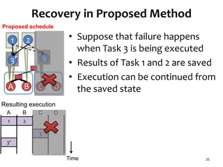
![Checkpointing and Recovery
• Each processor node saves state to the main memory
when each task is finished
Saved state is the data transferred to the succeeding processor
nodes
Only output data from each task node is saved as a state
• This is much smaller than the complete memory image
We assume saving state finishes instantaneously
• Since this is just copying small data within memory
• Recovery
Saved state which is not affected by the failure is found in the
ancestor task nodes.
Some tasks are executed again using the saved state
16
[3] Y. Gu, Z. Zhang, F. Ye, H. Yang, M. Kim, H. Lei, and Z. Liu. An empirical study of high
availability in stream processing systems. In Middleware ’09: the 10th
ACM/IFIP/USENIX International Conference on Middleware (Industrial Track), 2009.](https://image.slidesharecdn.com/120516ccgrid-120515132409-phpapp01/85/Slides-Task-scheduling-algorithm-for-multicore-processor-system-for-minimizing-recovery-time-in-case-of-single-node-fault-16-320.jpg)
![Task Graph with Low Parallelism
Configuration
• Number of task nodes:90
• Number of cores on a die:2
• Number of dies:2~4
• Robot control [4]
32
Task graph
Processor graph
10
Die
1 Core
Switch
4 5
Die
# of dies
32
Die
6 7
Die
[4] Standard Task Graph Set
http://www.kasahara.elec.waseda.ac.jp/schedule/index.html](https://image.slidesharecdn.com/120516ccgrid-120515132409-phpapp01/85/Slides-Task-scheduling-algorithm-for-multicore-processor-system-for-minimizing-recovery-time-in-case-of-single-node-fault-32-320.jpg)
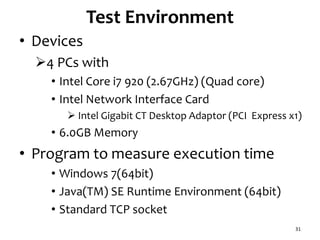
![Configuration
• Number of task nodes:98
• Number of cores on a die:4
• Number of dies:2~4
• Sparse matrix solver [4]
34
10
Die
1 Core
Switch
2 3 54
Die
6 7
# of dies
Task Graph with High Parallelism
Processor graph
Task graph
[4] Standard Task Graph Set
http://www.kasahara.elec.waseda.ac.jp/schedule/index.html](https://image.slidesharecdn.com/120516ccgrid-120515132409-phpapp01/85/Slides-Task-scheduling-algorithm-for-multicore-processor-system-for-minimizing-recovery-time-in-case-of-single-node-fault-34-320.jpg)
![Shohei Gotoda, Naoki Shibata and Minoru Ito :
"Task scheduling algorithm for multicore
processor system for minimizing recovery time
in case of single node fault," Proceedings of
IEEE International Symposium on Cluster
Computing and the Grid (CCGrid 2012), pp.260-
26, 2012.
DOI:10.1109/CCGrid.2012.23 [ PDF ]
40](https://image.slidesharecdn.com/120516ccgrid-120515132409-phpapp01/85/Slides-Task-scheduling-algorithm-for-multicore-processor-system-for-minimizing-recovery-time-in-case-of-single-node-fault-40-320.jpg)

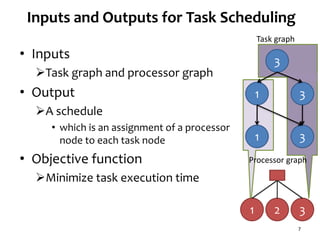
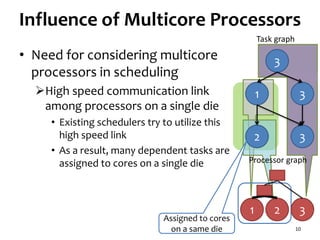
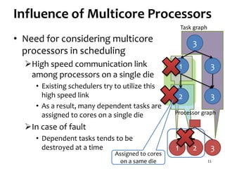
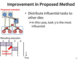
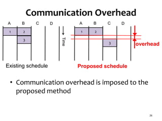
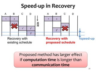
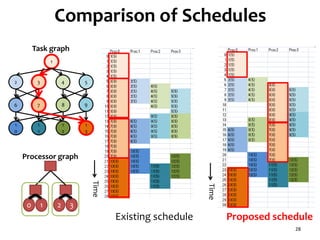
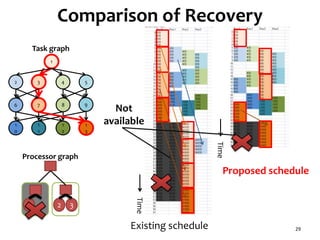
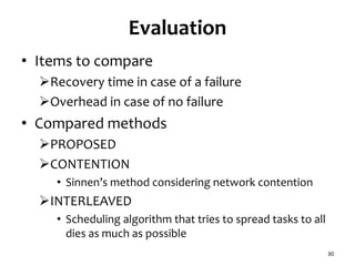
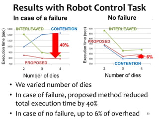
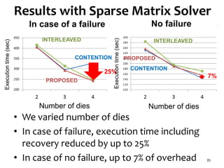
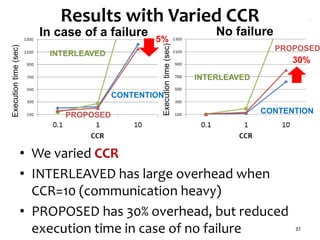
The document presents a task scheduling algorithm designed for multicore processors to minimize recovery time in case of a single node failure. It introduces a new scheduling method that accounts for network contention and multicore processor failure, aiming to improve upon existing methods that overlook these factors. Testing results show that the proposed method significantly reduces execution time during failures by optimizing task distribution across processor dies.