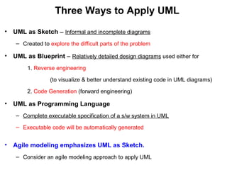
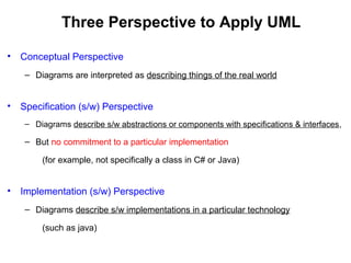
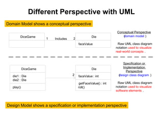
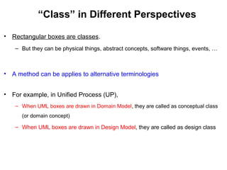
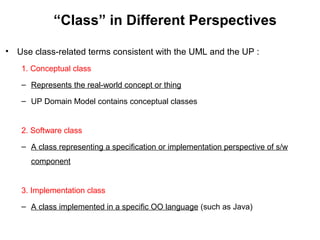
UNIT I UML DIAGRAMS
Introduction to OOAD – Unified Process –
UML diagrams – Use Case – Class Diagrams–
Interaction Diagrams – State Diagrams –
Activity Diagrams –
Package, component and Deployment Diagrams.
Unified Modeling Language (UML)
Standard Visual Modeling Language
For specifying, visualizing, constructing, and
documenting the artifacts of s/w systems,
as well as for business modeling and
other non-software systems
About UML
• UML is a standard modeling language, not a software
development process.
• In 1997 UML was adopted as a standard by the Object
Management Group (OMG)
• In 2005 UML was published by the International Organization
for Standardization (ISO) as an approved ISO standard
UML Support OO Software
• UML is generally used to model OO s/w applications
• OO design is transformed into UML diagrams
– According to the requirement.
• Input from the OO analysis and design is
– The input to the UML diagrams.
Three Ways to Apply UML
• UML as Sketch – Informal and incomplete diagrams
– Created to explore the difficult parts of the problem
• UML as Blueprint – Relatively detailed design diagrams used either for
1. Reverse engineering
(to visualize & better understand existing code in UML diagrams)
2. Code Generation (forward engineering)
• UML as Programming Language
– Complete executable specification of a s/w system in UML
– Executable code will be automatically generated
• Agile modeling emphasizes UML as Sketch.
– Consider an agile modeling approach to apply UML
Three Perspective to Apply UML
• Conceptual Perspective
– Diagrams are interpreted as describing things of the real world
• Specification (s/w) Perspective
– Diagrams describe s/w abstractions or components with specifications & interfaces,
– But no commitment to a particular implementation
(for example, not specifically a class in C# or Java)
• Implementation (s/w) Perspective
– Diagrams describe s/w implementations in a particular technology
(such as java)
Different Perspective with UML
Conceptual Perspective
(domain model )
Raw UML class diagram
notation used to visualize
real-world concepts .
Specification or
Implementation
Perspective
(design class diagram )
Raw UML class diagram
notation used to visualize
software elements .
2
Die
faceValue : int
getFaceValue() : int
roll()
DiceGame
die1 : Die
die2 : Die
play()
DiceGame Die
faceValue
Includes 21
Domain Model shows a conceptual perspective
Design Model shows a specification or implementation perspective
“Class” in Different Perspectives
• Rectangular boxes are classes.
– But they can be physical things, abstract concepts, software things, events, …
• A method can be applies to alternative terminologies
• For example, in Unified Process (UP),
– When UML boxes are drawn in Domain Model, they are called as conceptual class
(or domain concept)
– When UML boxes are drawn in Design Model, they are called as design class
“Class” in Different Perspectives
• Use class-related terms consistent with the UML and the UP :
1. Conceptual class
– Represents the real-world concept or thing
– UP Domain Model contains conceptual classes
2. Software class
– A class representing a specification or implementation perspective of s/w
component
3. Implementation class
– A class implemented in a specific OO language (such as Java)
02 uml

02 uml

  • 1.
    UNIT I UMLDIAGRAMS Introduction to OOAD – Unified Process – UML diagrams – Use Case – Class Diagrams– Interaction Diagrams – State Diagrams – Activity Diagrams – Package, component and Deployment Diagrams.
  • 2.
    Unified Modeling Language(UML) Standard Visual Modeling Language For specifying, visualizing, constructing, and documenting the artifacts of s/w systems, as well as for business modeling and other non-software systems
  • 3.
    About UML • UMLis a standard modeling language, not a software development process. • In 1997 UML was adopted as a standard by the Object Management Group (OMG) • In 2005 UML was published by the International Organization for Standardization (ISO) as an approved ISO standard
  • 4.
    UML Support OOSoftware • UML is generally used to model OO s/w applications • OO design is transformed into UML diagrams – According to the requirement. • Input from the OO analysis and design is – The input to the UML diagrams.
  • 5.
    Three Ways toApply UML • UML as Sketch – Informal and incomplete diagrams – Created to explore the difficult parts of the problem • UML as Blueprint – Relatively detailed design diagrams used either for 1. Reverse engineering (to visualize & better understand existing code in UML diagrams) 2. Code Generation (forward engineering) • UML as Programming Language – Complete executable specification of a s/w system in UML – Executable code will be automatically generated • Agile modeling emphasizes UML as Sketch. – Consider an agile modeling approach to apply UML
  • 6.
    Three Perspective toApply UML • Conceptual Perspective – Diagrams are interpreted as describing things of the real world • Specification (s/w) Perspective – Diagrams describe s/w abstractions or components with specifications & interfaces, – But no commitment to a particular implementation (for example, not specifically a class in C# or Java) • Implementation (s/w) Perspective – Diagrams describe s/w implementations in a particular technology (such as java)
  • 7.
    Different Perspective withUML Conceptual Perspective (domain model ) Raw UML class diagram notation used to visualize real-world concepts . Specification or Implementation Perspective (design class diagram ) Raw UML class diagram notation used to visualize software elements . 2 Die faceValue : int getFaceValue() : int roll() DiceGame die1 : Die die2 : Die play() DiceGame Die faceValue Includes 21 Domain Model shows a conceptual perspective Design Model shows a specification or implementation perspective
  • 8.
    “Class” in DifferentPerspectives • Rectangular boxes are classes. – But they can be physical things, abstract concepts, software things, events, … • A method can be applies to alternative terminologies • For example, in Unified Process (UP), – When UML boxes are drawn in Domain Model, they are called as conceptual class (or domain concept) – When UML boxes are drawn in Design Model, they are called as design class
  • 9.
    “Class” in DifferentPerspectives • Use class-related terms consistent with the UML and the UP : 1. Conceptual class – Represents the real-world concept or thing – UP Domain Model contains conceptual classes 2. Software class – A class representing a specification or implementation perspective of s/w component 3. Implementation class – A class implemented in a specific OO language (such as Java)