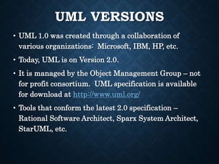
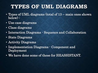
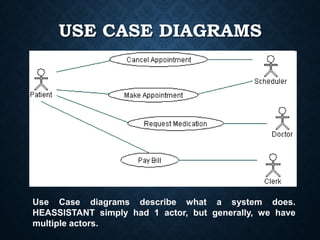
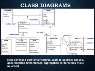
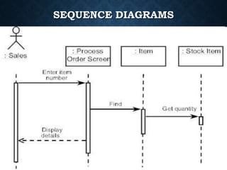
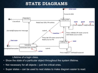
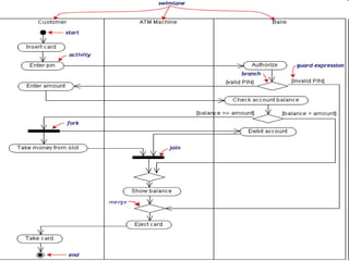
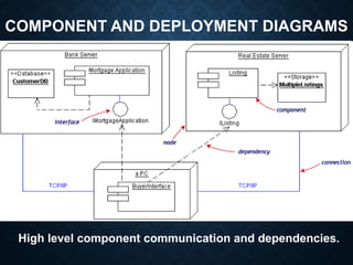
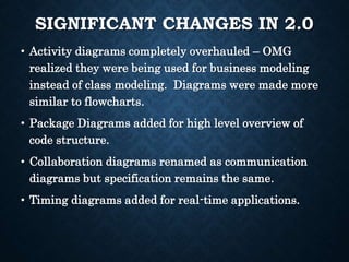
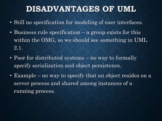
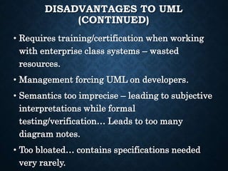
UML
By,
D. B. Naga Muruga,
Dept of Mechanical Engineering,
Sriram Engineering College.
OVERVIEW
• Introduction
• History
• Goals
• Diagrams and Examples
• Latest Changes
• Disadvantages
• Conclusion
WHAT IS UML?
• Unified Modeling Language (UML) is a standard language for
specifying, visualizing, constructing software artifacts.
• Not necessarily restricted to software systems – used in
business modeling.
• Has proven successful in modeling of large and complex
systems.
• Uses graphical notations to describe the architecture of
software.
• We have used UML in the diagrams for HEASSISTANT.
GOALS
• Provide users a expressive, visual language to
enable sharing of meaningful models.
• Enables developers to compare models before
implementation phase.
• Independent of programming language and
development process.
• Encourage growth of Object Oriented Tools
market.
HISTORY
• First modeling languages – 1970’s.
• More than 50 modeling languages present during 1994.
Lead to “method wars”.
• Methods began to incorporate each other’s techniques.
• In 1994, Grady Booch and Jim Rumbaugh (Rational
Software Corporation) unified Booch and Object
Modeling Technique methods to create UML.
• Ivar Jacobson incorporated the OOSE method in 1995,
leading to UML version 0.9 in late 1996.
UML VERSIONS
• UML 1.0 was created through a collaboration of
various organizations: Microsoft, IBM, HP, etc.
• Today, UML is on Version 2.0.
• It is managed by the Object Management Group – not
for profit consortium. UML specification is available
for download at http://www.uml.org/
• Tools that conform the latest 2.0 specification –
Rational Software Architect, Sparx System Architect,
StarUML, etc.
TYPES OF UML DIAGRAMS
• Types of UML diagrams (total of 13 – main ones shown
below) :
• Use case diagrams
• Class diagrams
• Interaction Diagrams - Sequence and Collaboration
• State Diagrams
• Activity Diagrams
• Implementation Diagrams - Component and
Deployment
• We have done some of these for HEASSISTANT.
USE CASE DIAGRAMS
Use Case diagrams describe what a system does.
HEASSISTANT simply had 1 actor, but generally, we have
multiple actors.
CLASS DIAGRAMS
Note advanced additional features such as abstract classes,
generalization (inheritance), aggregation (orderdetails make
up order)
SEQUENCE DIAGRAMS
COLLABORATION DIAGRAMS
• Note the use of sequence numbers
• Top level is assigned 1.1 – additional dots
per level away from the user interface.
STATE DIAGRAMS
• Show the state of a particular object throughout the system lifetime.
• Not necessary for all objects – just the critical ones.
• Super states – can be used to nest states to make diagram easier to read.
Lifetime of a login class.
ACTIVITY DIAGRAMS
• A flowchart of the activity in a system.
• Elegant way to show conditional flows of execution.
• For use in multithreaded environments – can show
creation of parallel threads of execution, stopping of
threads of execution.
• Usually one per use case. Objects involved are given
their own “swimlanes”.
• Example on next page shows activity flow for
"Withdraw money from a bank account through an
ATM.“
• Activities in parallel – debiting account, removing
money from slot.
COMPONENT AND DEPLOYMENT DIAGRAMS
High level component communication and dependencies.
CERTIFICATION
• OMG offers individual certification programs
for UML 2.0 with 3 levels – Fundamental,
Intermediate, and Advanced.
• Price per exam is 200 dollars, but
Fundamental is prerequisite to Intermediate..
etc.
• OMG also certifies UML compliant tools from
vendors.
• Gives vendors right to place “OMG certified”
logos on products and websites.
UML 2.0 STRUCTURE
• Comprised of four parts: superstructure,
Infrastructure, Object Constraint Language, Diagram
Interchange
• Superstructure – defines the UML diagrams. Large
710-page PDF free to download from OMG website.
• Infrastructure - defines the base classes/components
used by the Superstructure.
• Object Constraint Language – formal way of
specifying constraints on objects within a diagram
defined in the Superstructure.
• Diagram Interchange – standard for exchange and
storage/retrieval of UML diagrams for different software
tools.
STATE OF UML TODAY
• Size of the UML specification is growing tremendously.
• Changes are being made in the superstructure.
Example – timing diagrams added but weren’t present
in previous versions.
• Extensions to UML being written to handle other
technologies – CORBA, certain Security extensions.
• Requests for Proposal (RFP) are found on OMG
websites.
SIGNIFICANT CHANGES IN 2.0
• Activity diagrams completely overhauled – OMG
realized they were being used for business modeling
instead of class modeling. Diagrams were made more
similar to flowcharts.
• Package Diagrams added for high level overview of
code structure.
• Collaboration diagrams renamed as communication
diagrams but specification remains the same.
• Timing diagrams added for real-time applications.
DISADVANTAGES OF UML
• Still no specification for modeling of user interfaces.
• Business rule specification – a group exists for this
within the OMG, so we should see something in UML
2.1.
• Poor for distributed systems – no way to formally
specify serialization and object persistence.
• Example – no way to specify that an object resides on a
server process and shared among instances of a
running process.
DISADVANTAGES TO UML
(CONTINUED)
• Requires training/certification when working
with enterprise class systems – wasted
resources.
• Management forcing UML on developers.
• Semantics too imprecise – leading to subjective
interpretations while formal
testing/verification… Leads to too many
diagram notes.
• Too bloated… contains specifications needed
very rarely.
REFERENCES
• http://www.uml.org/
• http://atlas.kennesaw.edu/~dbraun/csis4650/A&D/UML_tutorial/
• http://bdn.borland.com/article/0,1410,31863,00.html
• http://en.wikipedia.org/wiki/Unified_Modeling_Language
Uml basics
Uml basics

Uml basics

  • 1.
    UML By, D. B. NagaMuruga, Dept of Mechanical Engineering, Sriram Engineering College.
  • 2.
    OVERVIEW • Introduction • History •Goals • Diagrams and Examples • Latest Changes • Disadvantages • Conclusion
  • 3.
    WHAT IS UML? •Unified Modeling Language (UML) is a standard language for specifying, visualizing, constructing software artifacts. • Not necessarily restricted to software systems – used in business modeling. • Has proven successful in modeling of large and complex systems. • Uses graphical notations to describe the architecture of software. • We have used UML in the diagrams for HEASSISTANT.
  • 4.
    GOALS • Provide usersa expressive, visual language to enable sharing of meaningful models. • Enables developers to compare models before implementation phase. • Independent of programming language and development process. • Encourage growth of Object Oriented Tools market.
  • 5.
    HISTORY • First modelinglanguages – 1970’s. • More than 50 modeling languages present during 1994. Lead to “method wars”. • Methods began to incorporate each other’s techniques. • In 1994, Grady Booch and Jim Rumbaugh (Rational Software Corporation) unified Booch and Object Modeling Technique methods to create UML. • Ivar Jacobson incorporated the OOSE method in 1995, leading to UML version 0.9 in late 1996.
  • 6.
    UML VERSIONS • UML1.0 was created through a collaboration of various organizations: Microsoft, IBM, HP, etc. • Today, UML is on Version 2.0. • It is managed by the Object Management Group – not for profit consortium. UML specification is available for download at http://www.uml.org/ • Tools that conform the latest 2.0 specification – Rational Software Architect, Sparx System Architect, StarUML, etc.
  • 7.
    TYPES OF UMLDIAGRAMS • Types of UML diagrams (total of 13 – main ones shown below) : • Use case diagrams • Class diagrams • Interaction Diagrams - Sequence and Collaboration • State Diagrams • Activity Diagrams • Implementation Diagrams - Component and Deployment • We have done some of these for HEASSISTANT.
  • 8.
    USE CASE DIAGRAMS UseCase diagrams describe what a system does. HEASSISTANT simply had 1 actor, but generally, we have multiple actors.
  • 9.
    CLASS DIAGRAMS Note advancedadditional features such as abstract classes, generalization (inheritance), aggregation (orderdetails make up order)
  • 10.
  • 11.
    COLLABORATION DIAGRAMS • Notethe use of sequence numbers • Top level is assigned 1.1 – additional dots per level away from the user interface.
  • 12.
    STATE DIAGRAMS • Showthe state of a particular object throughout the system lifetime. • Not necessary for all objects – just the critical ones. • Super states – can be used to nest states to make diagram easier to read. Lifetime of a login class.
  • 13.
    ACTIVITY DIAGRAMS • Aflowchart of the activity in a system. • Elegant way to show conditional flows of execution. • For use in multithreaded environments – can show creation of parallel threads of execution, stopping of threads of execution. • Usually one per use case. Objects involved are given their own “swimlanes”. • Example on next page shows activity flow for "Withdraw money from a bank account through an ATM.“ • Activities in parallel – debiting account, removing money from slot.
  • 15.
    COMPONENT AND DEPLOYMENTDIAGRAMS High level component communication and dependencies.
  • 16.
    CERTIFICATION • OMG offersindividual certification programs for UML 2.0 with 3 levels – Fundamental, Intermediate, and Advanced. • Price per exam is 200 dollars, but Fundamental is prerequisite to Intermediate.. etc. • OMG also certifies UML compliant tools from vendors. • Gives vendors right to place “OMG certified” logos on products and websites.
  • 17.
    UML 2.0 STRUCTURE •Comprised of four parts: superstructure, Infrastructure, Object Constraint Language, Diagram Interchange • Superstructure – defines the UML diagrams. Large 710-page PDF free to download from OMG website. • Infrastructure - defines the base classes/components used by the Superstructure. • Object Constraint Language – formal way of specifying constraints on objects within a diagram defined in the Superstructure. • Diagram Interchange – standard for exchange and storage/retrieval of UML diagrams for different software tools.
  • 18.
    STATE OF UMLTODAY • Size of the UML specification is growing tremendously. • Changes are being made in the superstructure. Example – timing diagrams added but weren’t present in previous versions. • Extensions to UML being written to handle other technologies – CORBA, certain Security extensions. • Requests for Proposal (RFP) are found on OMG websites.
  • 19.
    SIGNIFICANT CHANGES IN2.0 • Activity diagrams completely overhauled – OMG realized they were being used for business modeling instead of class modeling. Diagrams were made more similar to flowcharts. • Package Diagrams added for high level overview of code structure. • Collaboration diagrams renamed as communication diagrams but specification remains the same. • Timing diagrams added for real-time applications.
  • 20.
    DISADVANTAGES OF UML •Still no specification for modeling of user interfaces. • Business rule specification – a group exists for this within the OMG, so we should see something in UML 2.1. • Poor for distributed systems – no way to formally specify serialization and object persistence. • Example – no way to specify that an object resides on a server process and shared among instances of a running process.
  • 21.
    DISADVANTAGES TO UML (CONTINUED) •Requires training/certification when working with enterprise class systems – wasted resources. • Management forcing UML on developers. • Semantics too imprecise – leading to subjective interpretations while formal testing/verification… Leads to too many diagram notes. • Too bloated… contains specifications needed very rarely.
  • 22.
    REFERENCES • http://www.uml.org/ • http://atlas.kennesaw.edu/~dbraun/csis4650/A&D/UML_tutorial/ •http://bdn.borland.com/article/0,1410,31863,00.html • http://en.wikipedia.org/wiki/Unified_Modeling_Language