Scanning the Internet for External Cloud Exposures via SSL Certs
L37 3 ph-im
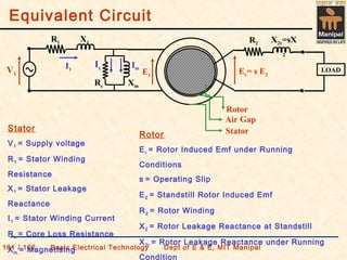
1. Equivalent Circuit
101 / 102 Basic Electrical Technology Dept of E & E, MIT Manipal
R1 X1
LOAD
Rc Xm
V1
R2 X2r=sX
2
I1
E1
Er= s E2
Ic Im
Rotor
Air Gap
StatorStator
V1 = Supply voltage
R1 = Stator Winding
Resistance
X1 = Stator Leakage
Reactance
I1 = Stator Winding Current
Rc = Core Loss Resistance
Xm = Magnetising
Rotor
Er = Rotor Induced Emf under Running
Conditions
s = Operating Slip
E2 = Standstill Rotor Induced Emf
R2 = Rotor Winding
X2 = Rotor Leakage Reactance at Standstill
X2r = Rotor Leakage Reactance under Running
Condition
2. Rotor Equivalent circuit
101 / 102 Basic Electrical Technology Dept of E & E, MIT Manipal
• Rotor windings offer resistance, represented by R2
• Presence of leakage flux, represented by X2
Standstill Operating
Emf E2 E2r = s E2
Resistan
ce
R2 R2
Reactanc
e
X2 X2r = s X2
Impedan
ce
Z2= R2 + j
X2
Z2r= R2 + j ( s
X2 )
Current I2 I2r
R2 X2r
E2r
I2r
3. Rotor Equivalent circuit cont’d …
101 / 102 Basic Electrical Technology Dept of E & E, MIT Manipal
X2
E2 I2r
s
R2
2
2
2
r22
r2
r2
Xj
s
R
E
XjR
E
I
+
=
+
=
X2
s
R2
E2 I2r
−= 1
s
1
RR 2LR2
X2
E
2
I2r
Mechanical load on the motor is represented by
−= 1
s
1
RR 2L
4. Power Output
101 / 102 Basic Electrical Technology Dept of E & E, MIT Manipal
−= 1
s
1
RR 2LR2
X2
E2
I2r
Gross Power Output
(Rotor Output)
−= 1
s
1
RI3P 2
2
2Gross
Net Power output
(actual Power output
or Shaft output)
PNet = PGross – PFriction & Windage Loss
5. Power Stages
101 / 102 Basic Electrical Technology Dept of E & E, MIT Manipal 1
Stator
Input
Stator
Losses
Stator Copper Loss
Core Loss
Stator Output
(Rotor Input)
Gross Power
Output
Net
Output
Other
Losses
Friction & Windage Loss
Stator Input = Motor Input (PIN) = √3 VLILCosΦ
Stator Losses = Stator Copper Loss (PSCU) + Core Loss (PCO) =
3I1
2
R1+ PCOtator Output = Stator Input - Stator Losses
Rotor Input = Stator Output
Rotor Losses = Rotor Copper Loss (PRCU) = 3I2
2
R2
Gross Power Output (Pg) = Rotor Input -
Rotor LossesPower Output (PO) = Gross Power Output (Pg) – Friction & Windage Losses (P
InputPowerMotor
OutputPowerNet
ηEfficiency =
Rotor Copper Loss
Rotor
Losses
6. Relationship between Rotor Quantities
101 / 102 Basic Electrical Technology Dept of E & E, MIT Manipal 2
• Pg = Gross output, Prcu = Rotor copper loss, P2 = Rotor input
Power transferred from stator to rotor = Rotor input =
60
TN2π
P s
2 =
Gross Power developed by the rotor =
60
TN2π
Pg =
Rotor copper loss, Prcu = P2 - Pg
2rcu PsP =
Rotor input (P2) = Rotor copper loss (Prcu) + Gross output (Pg)
2g Ps)-(1P =
s)(1:s:1P:P:P grcu2 −=
s
N
NN
P
P
S
Srcu
=
−
=
2
7. Relationship between Rotor Quantities
101 / 102 Basic Electrical Technology Dept of E & E, MIT Manipal 2
• Pg = Gross output, Prcu = Rotor copper loss, P2 = Rotor input
Power transferred from stator to rotor = Rotor input =
60
TN2π
P s
2 =
Gross Power developed by the rotor =
60
TN2π
Pg =
Rotor copper loss, Prcu = P2 - Pg
2rcu PsP =
Rotor input (P2) = Rotor copper loss (Prcu) + Gross output (Pg)
2g Ps)-(1P =
s)(1:s:1P:P:P grcu2 −=
s
N
NN
P
P
S
Srcu
=
−
=
2