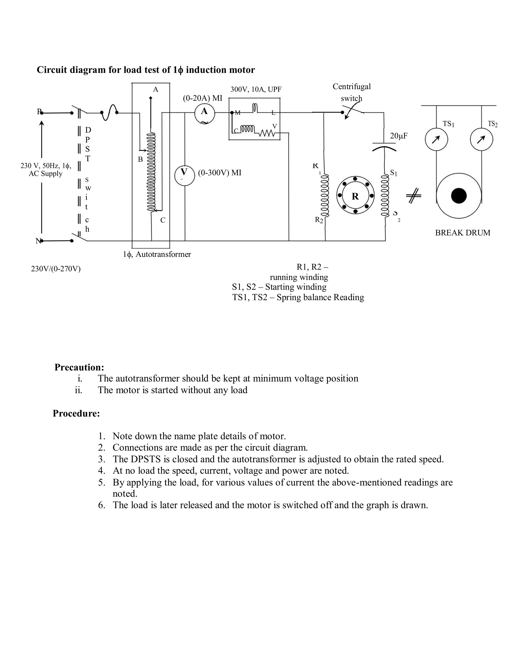
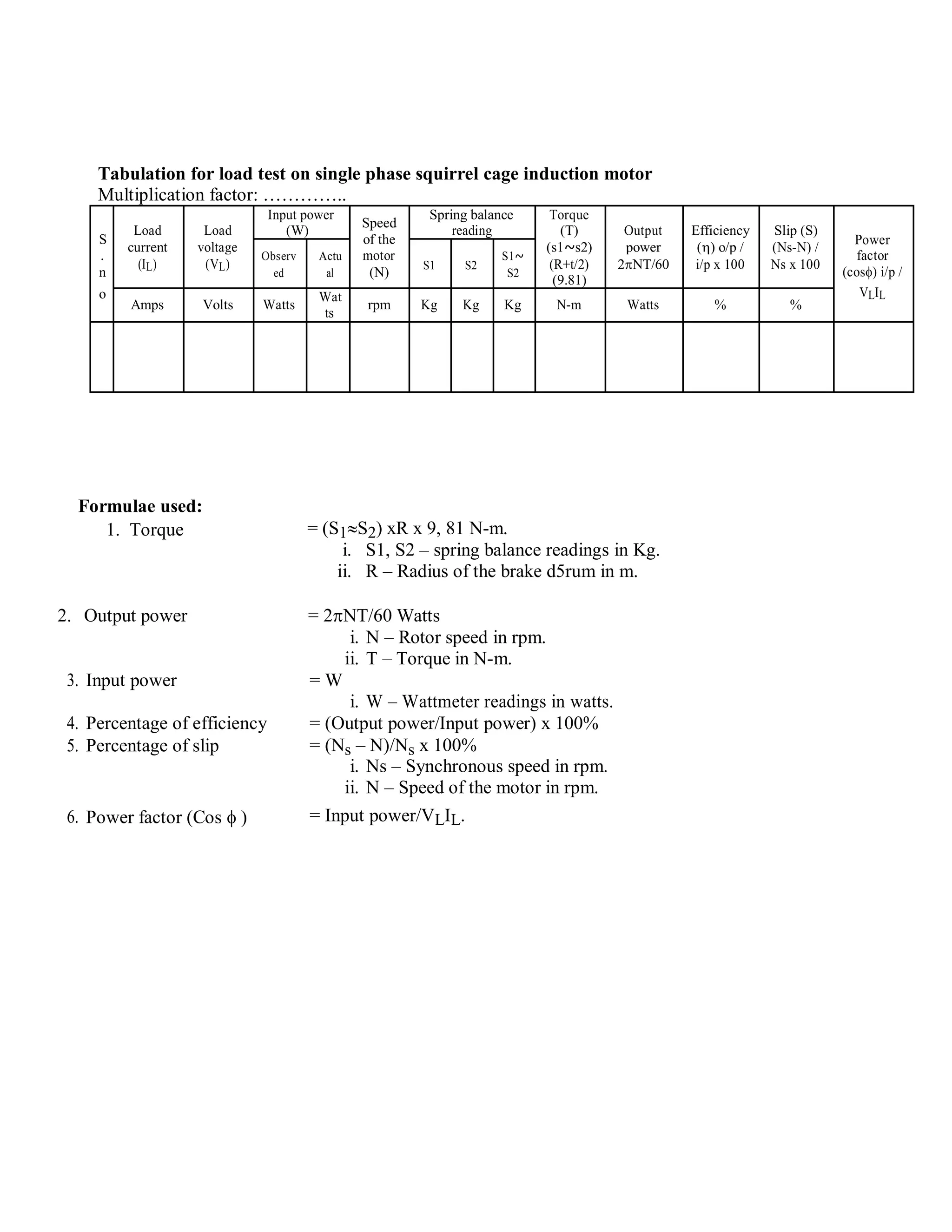
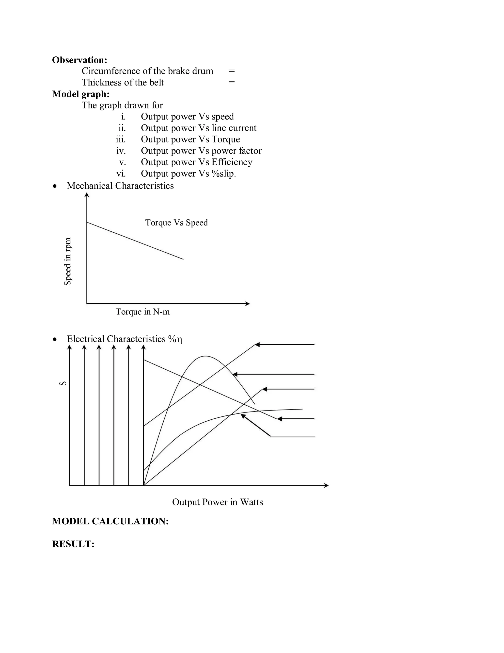
Load Test on Single - Phase Squirrel Cage Induction Motor
Aim:
To conduct the load test on single phase squirrel cage induction motor and to draw the
performance characteristics curves.
Apparatus required:
S.No Name of the Apparatus Type Range qty
1. Ammeter MI (O-20)A 1
2. voltmeter MI (0-300)V 1
3. Capacitor Electrolytic 440V/20Mfd 1
4. Wattmeter UPF (300V,10A) 1
5. Tachometer Digital 0-4000 rpm 1
6. Connecting Wire - 1100V, 10 A
As per
Required
NAME PLATE DETAILS:
1 Induction Motor
Theory:
Circuit diagram for load test of 1 induction motor
A 300V, 10A, UPF Centrifugal
switch(0-20A) MI
P A M L
D
~ C
V TS1 TS2
20µFP
S
230 V, 50Hz, 1,
T B
V (0-300V) MI
R
1 S1AC Supply
S ~
w
Ri
t
c C R2
S
2
h BREAK DRUM
N
1, Autotransformer
230V/(0-270V) R1, R2 –
running winding
S1, S2 – Starting winding
TS1, TS2 – Spring balance Reading
Precaution:
i. The autotransformer should be kept at minimum voltage position
ii. The motor is started without any load
Procedure:
1. Note down the name plate details of motor.
2. Connections are made as per the circuit diagram.
3. The DPSTS is closed and the autotransformer is adjusted to obtain the rated speed.
4. At no load the speed, current, voltage and power are noted.
5. By applying the load, for various values of current the above-mentioned readings are
noted.
6. The load is later released and the motor is switched off and the graph is drawn.
Tabulation for load test on single phase squirrel cage induction motor
Multiplication factor: …………..
Input power
Speed
Spring balance Torque
Load Load (W) reading (T) Output Efficiency Slip (S)
S of the Power
current voltage (s1~s2) power () o/p / (Ns-N) /
. Observ Actu motor S1~ factor
(IL) (VL) S1 S2 (R+t/2) 2NT/60 i/p x 100 Ns x 100
n ed al (N) S2 (cos) i/p /
(9.81)
o VLIL
Amps Volts Watts
Wat
rpm Kg Kg Kg N-m Watts % %
ts
Formulae used:
= (S1S2) xR x 9, 81 N-m.1. Torque
i. S1, S2 – spring balance readings in Kg.
ii. R – Radius of the brake d5rum in m.
2. Output power = 2NT/60 Watts
i. N – Rotor speed in rpm.
ii. T – Torque in N-m.
3. Input power = W
i. W – Wattmeter readings in watts.
4. Percentage of efficiency = (Output power/Input power) x 100%
5. Percentage of slip = (Ns – N)/Ns x 100%
i. Ns – Synchronous speed in rpm.
ii. N – Speed of the motor in rpm.
6. Power factor (Cos  ) = Input power/VLIL.
Observation:
Circumference of the brake drum =
Thickness of the belt =
Model graph:
The graph drawn for
i. Output power Vs speed
ii. Output power Vs line current
iii. Output power Vs Torque
iv. Output power Vs power factor
v. Output power Vs Efficiency
vi. Output power Vs %slip.
 Mechanical Characteristics
Torque Vs Speed
Speedinrpm
Torque in N-m
 Electrical Characteristics %
S

C
o
s
N
i
n
r
p
m
T
i
n
N
-
m
I
L
Output Power in Watts
MODEL CALCULATION:
RESULT:

Load test on single phase indution motor

  • 1.
    Load Test onSingle - Phase Squirrel Cage Induction Motor Aim: To conduct the load test on single phase squirrel cage induction motor and to draw the performance characteristics curves. Apparatus required: S.No Name of the Apparatus Type Range qty 1. Ammeter MI (O-20)A 1 2. voltmeter MI (0-300)V 1 3. Capacitor Electrolytic 440V/20Mfd 1 4. Wattmeter UPF (300V,10A) 1 5. Tachometer Digital 0-4000 rpm 1 6. Connecting Wire - 1100V, 10 A As per Required NAME PLATE DETAILS: 1 Induction Motor Theory:
  • 2.
    Circuit diagram forload test of 1 induction motor A 300V, 10A, UPF Centrifugal switch(0-20A) MI P A M L D ~ C V TS1 TS2 20µFP S 230 V, 50Hz, 1, T B V (0-300V) MI R 1 S1AC Supply S ~ w Ri t c C R2 S 2 h BREAK DRUM N 1, Autotransformer 230V/(0-270V) R1, R2 – running winding S1, S2 – Starting winding TS1, TS2 – Spring balance Reading Precaution: i. The autotransformer should be kept at minimum voltage position ii. The motor is started without any load Procedure: 1. Note down the name plate details of motor. 2. Connections are made as per the circuit diagram. 3. The DPSTS is closed and the autotransformer is adjusted to obtain the rated speed. 4. At no load the speed, current, voltage and power are noted. 5. By applying the load, for various values of current the above-mentioned readings are noted. 6. The load is later released and the motor is switched off and the graph is drawn.
  • 3.
    Tabulation for loadtest on single phase squirrel cage induction motor Multiplication factor: ………….. Input power Speed Spring balance Torque Load Load (W) reading (T) Output Efficiency Slip (S) S of the Power current voltage (s1~s2) power () o/p / (Ns-N) / . Observ Actu motor S1~ factor (IL) (VL) S1 S2 (R+t/2) 2NT/60 i/p x 100 Ns x 100 n ed al (N) S2 (cos) i/p / (9.81) o VLIL Amps Volts Watts Wat rpm Kg Kg Kg N-m Watts % % ts Formulae used: = (S1S2) xR x 9, 81 N-m.1. Torque i. S1, S2 – spring balance readings in Kg. ii. R – Radius of the brake d5rum in m. 2. Output power = 2NT/60 Watts i. N – Rotor speed in rpm. ii. T – Torque in N-m. 3. Input power = W i. W – Wattmeter readings in watts. 4. Percentage of efficiency = (Output power/Input power) x 100% 5. Percentage of slip = (Ns – N)/Ns x 100% i. Ns – Synchronous speed in rpm. ii. N – Speed of the motor in rpm. 6. Power factor (Cos  ) = Input power/VLIL.
  • 4.
    Observation: Circumference of thebrake drum = Thickness of the belt = Model graph: The graph drawn for i. Output power Vs speed ii. Output power Vs line current iii. Output power Vs Torque iv. Output power Vs power factor v. Output power Vs Efficiency vi. Output power Vs %slip.  Mechanical Characteristics Torque Vs Speed Speedinrpm Torque in N-m  Electrical Characteristics % S  C o s N i n r p m T i n N - m I L Output Power in Watts MODEL CALCULATION: RESULT: