
Recommended
More Related Content
What's hot
What's hot (20)
Similar to UNIT IV design of Electrical Apparatus
Similar to UNIT IV design of Electrical Apparatus (20)
Recently uploaded
Recently uploaded (20)
UNIT IV design of Electrical Apparatus
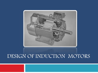
- 1. DESIGN OF INDUCTION MOTORS
- 2. Introduction Induction motors are the prime movers in most of the Industries (Work Horse of Motion Industries) simple design, rugged, low-price, easy maintenance wide range of power ratings: fractional horsepower to 10 MW run essentially as constant speed from no-load to full load Its speed depends on the frequency of the power source applications such as centrifugal pumps, conveyers, compressors crushers, and drilling machines etc 2
- 3. Construction Details AC induction motor comprises two electromagnetic parts Stationary part called the stator Rotating part called the rotor Differs from a dc machine in the following aspects. Laminated stator Absence of commutator & Uniform and small air gap Practically almost constant speed The stator and the rotor are each made up of An electric circuit - usually made of insulated copper or aluminum winding, to carry current A magnetic circuit - usually made from laminated 3
- 4. Stator - Construction The stator is the outer stationary part of the motor outer cylindrical frame - yoke which is made either of welded sheet steel, cast iron or cast aluminum alloy The magnetic path - comprises a set of slotted steel laminations called stator core pressed into the cylindrical space inside the outer frame. It is laminated to reduce eddy currents, reducing losses and heating Smooth Yoke Ribbed Yoke 4
- 5. Stator - Construction A set of insulated electrical windings, which are placed inside the slots of the laminated Stator. For a 3-phase motor, 3 sets of windings are required, one for each phase connected in either star or delta.. Stator Laminations cross sectional view of an induction motor 5
- 6. Rotor - Construction Rotor is the rotating part of the induction motor of a set of slotted silicon steel laminations pressed together to form of a cylindrical magnetic circuit and the electrical circuit The electrical circuit of the rotor is of Squirrel cage rotor Wound rotor (Slip Ring Rotor) 6
- 7. Squirrel Cage Rotor set of copper or aluminum bars installed into the slots, which are connected to an end-ring at each end of the rotor windings resembles a ‘squirrel cage bars ring ring bar s ring ring Even though the aluminum rotor bars are in direct contact with the steel laminations, practically all the rotor current flows through the aluminum bars and not in the lamination 7
- 8. Wound Rotor consists of three sets of insulated windings with connections brought out to three slip rings mounted on one end of the shaft The external connections to the rotor are made through brushes onto the slip rings Brushe Slip rings 8
- 9. Some more parts Two end- flanges to support the two bearings, one at the driving-end and the other at the non driving-end. Two sets of bearings to support the rotating shaft Steel shaft for transmitting the mechanical power to the load Cooling fan located at the non driving end Terminal box on top of the yoke or on side to receive the 9
- 10. 10
- 11. Main purpose of designing is to obtain the complete physical dimensions of all the parts to satisfy the customer Needs Physical Dimensions The main dimensions of the stator. Details of stator windings. Design details of rotor and its windings Performance characteristics (iron and copper losses, no load current, power factor, temperature rise and efficiency) Customer Needs out put power, voltage, number of phases, speed, frequency, connection of stator winding, type of rotor 11
- 12. Output Equation mathematical expression which gives the relation between the various physical and electrical parameters of the electrical machine 12
- 13. Output Equation Vph = phase voltage Iph = phase current Iz = Current in each Conductor Z = Total no of conductors Tph = no of turns/phase Ns = Synchronous speed in rpm ns = synchronous speed in rps p = no of poles, ac = Specific electric loading Ø= air gap flux/pole Bav = Average flux density kw = winding factor eff = efficiency cos Ø = power factor D = Diameter of the stator, L = Gross core length Co = Output coefficient 13
- 14. Output Equation For a 3 Ø machine, kVA rating Q = 3 Vph Iph 10-3 kW Assuming, Vph = Eph Eph = 4.44 f Ø Tph kW f = PNS/120 = P ns/2 Output = 3 x 4.44 x Pns/2 x Ø Tph Kw Iph x 10-3 kW Output = 6.66 x PØ x Iph Tph x ns x Kw x 10-3 kW Iz = Iph / a Let Iz = Iph (1 Parallel Path) Z = 3 x 2 Tph ( Tph = Z/6) 14
- 15. Output Equation Total Magnetic Loading PØ = Bav π DL Total Electric Loading ac = Iz Z/ π. D Output = 1.11 x PØ x Iz Z x ns x Kw x 10-3 kW Output = 1.11 x Bav π. DL x ac x π. D x ns x Kw x 10-3 kW Output = 11 Bav ac Kw 10-3 x D2L ns kW Output (Q) = Co D2L ns kW Where, Co = 11 Bav ac Kw 10-3 kVA input Q = H.P x 0.746 (kW) / eff cos Ø 15
- 16. Choice of Specific loadings Specific Magnetic loading or Air gap flux density (Bav) Iron losses largely depend upon air gap flux density Limitations : Magnetising current high – Poor power factor Flux density in teeth < 1.8 Tesla Flux density in core 1.3 – 1.5 Tesla Advantages of Higher value of Bav Large Flux/Pole – Tph less – Leakage reactance less - Overload capacity increases Size of the machine reduced Cost of the machine decreases For 50 Hz machine, The suitable values of Bav is 0.35 – 0.6 Tesla. 16
- 17. Choice of Specific loadings Specific Electric Loading (ac) Advantages of Higher value Reduced size Reduced cost Disadvantages of Higher value Higher amount of copper More copper losses Increased temperature rise Lower overload capacity Normal range 10000 ac/m – 450000 ac/m. For Machines high voltage rating – ac value Small 17
- 18. Choice of power factor and efficiency power factor and efficiency under full load conditions will increase with increase in rating of the machine Percentage magnetizing current and losses will be lower for a larger machine than that of a smaller machine the power factor and efficiency will be higher for a high speed machine than the same rated low speed machine because of better cooling conditions Squirrel cage – Efficiency – 0.72 to 0.91 & P.F – 0.66 to 0.9 Slip ring - Efficiency – 0.84 to 0.91 & P.F – 0.7 to 0.92 18
- 19. Separation of D and L The output equation gives the relation between D2L product and output of the machine The separation of D and L for this product depends on a suitable ratio between gross length and pole pitch ( L / τ) to obtain the best power factor the following relation will be usually assumed for separation of D and L. Pole pitch/ Core length = 0.18/pole pitch DesignEconomicalOverall higherfor PFGoodfor DesignOverallGood L :0.25.1 :5.1 :25.11 :1 D = 0.135 P Sqrt (L) 19
- 20. Peripheral Speed D and L have to satisfy the condition imposed on the value of peripheral speed For the normal design of induction motors the calculated diameter of the motor should be such that the peripheral speed must be below 30 m/s. In case of specially designed rotor the peripheral speed can be 60 m/s. Ventilating Ducts : Provided when core length exceeds 100 – 125 mm. The width of Duct – 8 to 10 mm 20
- 21. Design of Stator The Design consideration of Stator Involves in estimation of Stator Winding Stator Turns per Phase Length of Mean Turn Stator Conductors Shape & No of Stator Slots Area of Stator Slot Stator Teeth Depth of Stator Core 21
- 22. Stator Winding For Small Motors up to 5 HP Single layer Winding like Mush Winding Whole coil Concentric Winding Bifurcated concentric winding is used. Generally Double layer Winding ( Lap or Wave ) with diamond shaped coils is used. The three phases of winding can be connected in either star or Delta depending on the Starting Methods Employed. Squirrel cage – Star Delta Starter – Stators designed - Delta Slip ring – Rotor resistance – Either star or Delta 22
- 23. 23
- 24. 24
- 25. 25
- 26. Stator Turns per phase Stator Phase Voltage Es = 4.44 f Ø Ts Kws Stator Turns per phase Ts = Es / 4.44 f Ø Kws Where, Kws = 0.955 Winding factor Specific Magnetic Loading, Bav = Flux per pole / Area under a pole = p Ø / pi . D L Ø = Bav x pi . D L / p 26
- 27. Length of Mean Turn of winding For Stators that use up to 650 V Length of Mean turn , Lmts = 2L + 2.3 τ + 0.24 Where, L – Length of Stator Core τ - Pole Pitch Resistance of the stator winding per phase is calculated using the formula = (0.021 x lmt x Tph ) / as where lmt is in meter and as is in mm2 27
- 28. Stator Conductors kVA rating Q = 3 Es Is 10-3 kW Stator Current / Phase , Is = Q / 3 Es x 10-3 Area of Cross Section , as = Is / gs Where, gs – Current Density – 3 to 5 A/mm2 Area of Cross Section , as = pi ds 2 / 4 Where, ds – Diameter of Stator Conductor Round conductors are generally used For diameter more than 2 or 3 mm – Bar or Strip conductors are used 28
- 29. Stator Slots In general two types of stator slots - open slots and semiclosed slots Open Slots : slot opening will be equal to that of the width of the slots. assembly and repair of winding are easy. slots will lead to higher air gap contraction factor and hence poor power factor open slots 29
- 30. Stator Slots Semi enclosed Slots : slot opening is much smaller than the width of the slot. assembly of windings is more difficult and takes more time compared to open slots costlier Air gap characteristics are better compared to open type slots 30
- 31. Choice of Stator Slots number of slots/pole/phase may be selected as three or more for integral slot winding fractional slot windings number of slots/pole/phase may be selected as 3.5 Slot Pitch for open type of Slots should be 15 to 25 mm. Slot Pitch for Semi enclosed type of Slots should be < 15 mm. Stator slot pitch, Yss = Gap Surface / Total No of Slots = π . D / Ss So, Ss = π . D / Yss Stator Slots Ss = Number of phases x poles x slots/pole/phase 31
- 32. Conductors per Slot Total No of Stator Conductors Zs = Phase x Conductors/Phase = 3 x 2 Ts = 6 Ts Conductors per Slot, Zss = Total No of Zs / Total No of Ss = 6 Ts / Ss Where, Ts – Stator Turns per Phase Ss – Total Stator Slots Zss – Must be Even for double layer winding 32
- 33. Area of Stator Slot Area of each slot = Copper Area per slot / Space Factor = Zss x as / Space factor Where, Zss – No of Conductors per slot as – Area of each Conductor Space Factor – 0.25 to 0.4 33
- 34. Stator Teeth The Dimensions of slot determine the flux density in the teeth. Higher Flux Density – iron loss – Greater Magnetising mmf. Mean Flux density in tooth < 1.7 Wb/m2 Minimum teeth Area per pole = Øm / 1.7 Teeth area per pole = Ss / p x Li x Wts (Width of stator Tooth) So, Øm / 1.7 = (Ss / p) x Li x Wts min Wts min = Øm / 1.7 (Ss / p ) x Li 34
- 35. Depth of Stator Core flux density in Stator Core < 1.5 Wb/m2. So,Flux in core = half of flux / pole = Øm / 2 Area = Flux / Flux Density = (Øm / 2 ) / Bcs Also, Area = Li x depth (dcs) (Øm / 2 ) / Bcs = Li x dcs Depth of the core, dcs = Øm / 2 Bcs Li Outer Diameter,Do = D + 2(dss + Do dcs dss D 35
- 36. 36
- 37. 37
- 38. 38
- 39. 39
- 40. Length of Air Gap Advantages larger air gap length : Increased overload capacity Increased cooling Reduced unbalanced magnetic pull Reduced in tooth pulsation Reduced noise Disadvantages of larger air gap length Increased Magnetising current Reduced power factor For Small Induction Motor – lg = 0.2 + 2 Sqrt(DL) mm Lg = 0.125 +0.35D+ L + 0.015 Va mm For General Use - lg =0.2 + D mm For journal bearings - lg = 1.6 sqrt (D) – 0.25 mm 40
- 41. 41
- 42. 42
- 43. 43
- 44. Design of Rotor squirrel cage type are rugged and simple in construction and comparatively cheaper & has lower starting torque. In this type, the rotor consists of bars of copper or aluminum accommodated in rotor slots. Slip ring induction motors are complex in construction and costlier with the advantage that they have the better starting torque. This type of rotor consists of star connected distributed three phase windings. 44
- 45. Design of Rotor Cogging and Crawling are the two phenomena which are observed due to wrong combination of number of rotor and stator slots. In addition, induction motor may develop unpredictable hooks and cusps in torque speed characteristics or the motor may run with lot of noise 45
- 46. Crawling The rotating magnetic field produced in the air gap of the will be usually non sinusoidal and generally contains odd harmonics of the order 3rd, 5th and 7th The third harmonic flux will produce the three times the magnetic poles compared to that of the fundamental. Similarly the 5th and 7th harmonics The motor with presence of 7th harmonics is to have a tendency to run the motor at one seventh of its normal speed 46
- 47. Cogging When the number of rotor slots are not proper in relation to number of stator slots the machine refuses to run and remains stationary. Under such conditions there will be a locking tendency between the rotor and stator – Cogging rotor slots will be skewed by one slot pitch to minimize the tendency of cogging, torque defects like synchronous hooks and cusps and noisy operation while running. 47
- 48. Squirrel Vz Wound No Slip rings Higher Efficiency Star – Delta starter sufficient Cheaper Small copper loss Better P.F, greater Overload Capacity 48 Possible to insert resistance in rotor – Increases starting Torque Low starting current Rotor Resistance starter
- 49. Design of Squirrel Cage Rotor The Design involves Diameter of the Rotor Choice and Design of Rotor bars & slots Design of End Rings Diameter of Rotor Should be Slightly less than that of Stator to avoid Mechanical Friction Diameter of Rotor, Dr = D – 2 lg Where, D – Diameter of Stator Bore lg – length of air gap 49 bar s ring ring
- 50. Choice of Rotor Slots To avoid cogging and crawling: (a)Ss Sr (b) Ss - Sr ±3P To avoid synchronous hooks and cusps in torque speed characteristics ±P, ±2P, ±5P. To noisy operation Ss - Sr ±1, ±2, (±P ±1), (±P ±2) Design of Rotor Bars Rotor bar current, Ib= (6 Is Ts Kws cos Ø) / Sr = 0.85 x (6 Is Ts) / Sr (approx) Where , Is – Stator Current per Phase Ts – Stator Turns per phase Sr – Number of rotor slots Kws – Winding factor of stator 50
- 51. Design of Rotor Bars Area of each rotor bar, ab = Ib / gb in mm2 Where, Ib – Rotor bar current gb – Current density of rotor bar , Normally 4 – 7 A/mm2 Copper loss in rotor bars Length of rotor bar Lb = L + allowance for skewing Rotor bar resistance, rb = 0.021 x Lb / ab Copper loss in rotor bars = Ib 2 x rb x number of rotor bars 51
- 52. Design of End Rings All the rotor bars are short circuited by connecting them to the end rings The rotating magnetic filed produced will induce an emf in the rotor bars which will be sinusoidal over one pole pitch. As the rotor is a short circuited body, there will be current flow because of this emf induced. In one pole pitch, half of the number of bars and the end ring carry the current in one direction and the other half in the opposite direction. Thus the maximum end ring current may be taken as the sum of the average current in half of the number of bars under one pole. 52
- 53. 53
- 54. Design of End Rings Maximum value of End ring current, Ie(max) = ½ x ( Number rotor bars / pole) x Ib(av) = ½ x (Sr/p) x Ib(av) Where Ib(av) = (2/π) x Ib(max) Ib(max) = √2 Ib Since Bar current is Sinusoidal Ie(max) = √2 Sr Ib / πp Rms value of ring current = Ie = Ie(max) / √2 54
- 55. Design of End Rings Area of end rings Area of each end ring ae = Ie / ge mm2, Where ge = Current density in end ring – 4 to 7 A/mm2 Area of each end ring ae = depth x Thickness of end ring Area of each end ring ae = de x te Copper loss in End Rings Mean diameter of the end ring (Dme) - 4 to 6 cms less of the rotor Mean length of the current path in end ring lme = π Dme resistance of the end ring re = 0.021 x lme / ae Total copper loss in end rings = 2 x Ie2 x re 55
- 56. Design of Wound Rotor Rotor carries distributed star connected 3 phase winding Three ends of the winding are connected to the slip rings External resistances can be connected to these slip rings at starting, which will be inserted in series with the windings which will help in increasing the torque at starting The Design involves in Rotor winding Number of Rotor slots Number of rotor turns Rotor Current Area of rotor conductor Dimensions of rotor teeth Rotor core & Slip rings , brushes 56
- 57. Design of Wound Rotor Rotor winding : Small Motors – Mush Type : Large Motors – Double layer Bar Type : Motors > 750 kW – Barrel winding No of Rotor turns Turns ratio Er/Es = Kwr Tr / Kws Ts Rotor turns/ phase, Tr = Kws Ts Er / Kwr Es rotor ampere turn = 0.85 x stator ampere turn Ir Tr = 0.85 x Is Ts Rotor current Ir = 0.85 Is Ts / Tr 57
- 58. Design of Wound Rotor Area of rotor conductor, ar = Ir / gr Where gr – current density – 3 to 5 A/mm2 Choice of rotor slots Rotor slots should not be equal to stator slots Generally for wound rotor motors a suitable value is assumed for number of rotor slots per pole per phase, and then total number of of rotor slots are calculated. Semi closed slots are used for rotor slots. 58
- 59. Design of Wound Rotor Rotor teeth flux density in rotor tooth < 1.7 Wb/m2 Minimum teeth area / pole = Flux per pole / Max flux density = Øm / 1.7 Tooth area / pole = No of rotor slots/pole x Net iron length x width of the tooth = (Sr / p) x Li x Wtr Equating both (Sr / p) x Li x Wtr = Øm / 1.7 Wtr(min) = Øm / (1.7 x (Sr / p) x Li ) Wtr(min) actual = root Rotor slot pitch – rotor slot width = π (Dr – 2 dsr) / Sr - Wsr 59
- 60. Design of Wound Rotor Rotor Core The flux density in the rotor core = Stator core density Depth of rotor core, dcr = Øm / (2 x Bcr x Li ) Where, Bcr – Flux density in rotor core Inner Diameter of rotor lamination, Di = Dr – 2(dsr + dcr) Where, dcr – depth of rotor core dsr – depth of rotor slot Slip ring & brushes: Area of Slip ring = rotor current / Current density ( 4 to 7 A/mm2) Dimension of Brushes - Current density ( 0.1 to 0.2 A/mm2) 60
- 61. Performance Evaluation The parameters for performance evaluation are iron losses, no load current, no load power factor, leakage reactance etc Iron losses: Iron loss has two components, hysteresis and eddy current losses occurring in the iron parts depend upon the frequency of the applied voltage The frequency of the induced voltage in rotor is equal to the slip frequency which is very low and hence the iron losses occurring in the rotor is negligibly small. Hence the iron losses occurring in the induction motor is mainly due to the losses in the stator alone Total iron losses in induction motor = Iron loss in stator core + iron losses in stator teeth. 61
- 63. 63
- 64. 64
- 65. 65
- 66. 66
- 67. Leakage Calculations – Poly Phase 67
- 68. Short Circuit (Blocked Rotor) Current Resistance and Leakage Reactance - Needs to be evaluated Find the Stator and Rotor Resistance Find total resistance of motor as viewed from stator Finally Find Rotor current If rotor leakage reactance & Loss component of No load current – Neglected Stator current equivalent to rotor current = Is cos Ø Where Is – Stator current cos Ø - Power Factor 68
- 70. Circle Diagram We should know following for drawing the circle diagram No load current and no load power factor Short circuit current and short circuit power factor Draw I0 at an angle from vertical line assuming some scale for current. Draw Isc at an angle from vertical line. Join AB, which represents the o/p line of the motor to power scale. Draw a horizontal line AF, and erect a perpendicular bisector on the o/p line AB so as to meet the line AF at the point O’. Then O’ as center and AO’ as radius, draw a semi circle ABF. Draw vertical line BD; divide line BD in the ratio of rotor copper loss to stator copper loss at the point E. Join AE, which represent the torque line 70
- 71. Circle Diagram Full load current & power factor Draw a vertical line BC representing the rated o/p of the motor s per the power scale. From point C, draw a line parallel to o/p line, so as to cut the circle at pint P. Join OP which represents the full load current of the motor to current scale. Operating power factor can also be found out. Full load efficiency Draw a vertical line from P as shown in above figure. PL = O/p Power PX = I/p Power 71
- 72. Circle Diagram PowerInputRotor lossCuRotor Slip Slip PS LS Starting torque Line BE represents the starting torque of the motor in synchronous watts to power scale 72
- 73. Problems Solution: kVA input, Q = output / eff x P.F Co = 11 Bav ac Kw 10-3 Ns = 2f / p rps Sub the value of Co & ns in o/p equation Q = Co D2L ns Find D2L Estimate the stator core dimensions, number of stator slots, no of stator Conductors per slot for a 100kW, 3300V, 50Hz, 12 pole, Star connected slip ring induction motor Bav = 0.4 Wb/m2, ac = 25000 amp.cond/m, Eff = 0.9, P.F = 0.9, Choose the main dimensions to give best power factor. The slot loading should not exceed 500 amp.cond 73
- 74. Problems For best power factor τ = √(0.18L) we get a equation in terms of D & L Sub and solve for D & L. Stator star connected Es = El/√3 Flux per pole Ø = Bav π DL / p Find Ts using Flux Ts = Es / 4.44 f Ø Kws Slot pitch should be 15 to 25 mm Find Ss when Yss = 15 & 25 mm Ss = π . D / Yss 74
- 75. Problems We get a range of Ss from the above step Now Assume q = 2, 3, 4..etc and find Ss Stator Slots Ss = Number of phases x poles x slots/pole/phase Select Ss that is within the range Check for Slot loading = Is .Zss Since Star connected Il = I ph = Is Is = kVA x 103 / 3 x VL & Zss = 6 Ts / Ss Finalise the no of slots Ss Now find the new Total stator conductors = Ss .Zss & Turns / Phase, Ts = Zss . Ss / 6 75
- 76. Problems 76 Estimate the main dimensions, air gap length, number of stator slots, stator turns / phase & cross sectional area of stator and rotor conductors for a 3 phase, 15HP, 400V, 50Hz, 6, 975rpm induction motor, The motor is suitable for star delta starting. Bav = 0.45 Wb/m2, ac = 20000 amp.cond/m, Eff = 0.9, P.F = 0.85, L/τ = 0.85. Solution: kVA input, Q = HP X 0.746 / eff x P.F Co = 11 Bav ac Kw 10-3 Ns = 2f / p rps Sub the value of Co & ns in o/p equation Q = Co D2L ns Find D2L
- 77. Problems 77 Given L/τ = 0.85, Where τ = πd/p we get a equation in terms of D & L Substitute and solve for D & L. Delta connected Es = El = Eph Flux per pole Ø = Bav π DL / p Find Ts using Flux Ts = Es / 4.44 f Ø Kws Slot pitch should be 15 to 25 mm Find Ss when Yss = 15 & 25 mm Ss = π . D / Yss
- 78. Problems 78 We get a range of Ss from the above step Now Assume q = 2, 3, 4..etc and find Ss Stator Slots Ss = Number of phases x poles x slots/pole/phase Select Ss that is within the range Finalise the no of slots Ss Find Zss = 6 Ts / Ss Now find the new Total stator conductors = Ss .Zss & Turns / Phase, Ts = Zss . Ss / 6
- 79. Problems 79 Assume gs = 3 A/mm2 find Area Stator conductor as = Is / gs Where Is = Iph = Q x 103 / 3 Eph Length of Airgap, lg = 0.2 + 2 Sqrt(DL) mm Choose the No of Rotor slots Such that Ss – Sr are not equal Find Rotor bar current, Ib = 0.85 x (6 Is Ts) / Sr Assume gr = 4 A/mm2 find Area of rotor ar = Ir / gr Find End Ring Current, Ie = Sr Ib / πp Assume ge = 4 A/mm2 find Area of End rings ae = Ie / ge
- 80. Problems 80 Design a cage rotor for a 40 HP, 3 Phase , 400 V, 50 Hz, 6 pole, delta connected induction motor having a full load efficiency 87% and a full load P.F of 0.85. Take D =33 cm and L = 17 cm. Stator slots = 54, conductors per slot = 14. Assume suitably the missing data if any. Given: 3 phase, p=6, Ss =54, Zss = 14, Q=40 HP, Delta connected, V=400 V, Eff. = 0.87, P.f = 0.85, D=0.33m, L= 17m Solution: kVA input, Q = HP X 0.746 / eff x P.F
- 81. Problems 81 Choose the No of Rotor slots Such that Ss – Sr are not equal to 0,±p, ,±2p, ,±3p, ,±5p, ±1, ±2, ±(p ±1), ±(p ±2) 0,±6, ,±12, ,±18,±30, ±1, ±2, ±7,±5, ±8, ±4 Ss – Sr = ±3, ±9 Choose the minimum and Sr = 54-3 = 51 Find Rotor bar current, Ib = 0.85 x (6 Is Ts) / Sr Find Is and Ts Zss = 6 Ts / Ss, Ts = Zss x Ss /6 find Is from input KVA = 3 Eph x Iph x 10-3 Since delta connected, Eph =V = 400, Iph = Q / 3 Eph x 10-3
- 82. Problems 82 Find End Ring Current, Ie = Sr Ib / πp Assume gr = 4 A/mm2 find Area of rotor Bar ar = Ir / gr Assume ge = 4 A/mm2 find Area of End rings ae = Ie / ge Find length of rotor core = length of stator core Find Diameter of rotor = Dr = D – 2lg Find Length of Airgap, lg = 0.2 + 2 Sqrt(DL) mm