
Recommended
More Related Content
What's hot
What's hot (20)
Similar to 4606
Similar to 4606 (20)
Recently uploaded
Recently uploaded (20)
4606
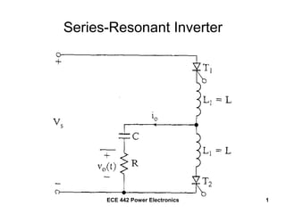
- 1. ECE 442 Power Electronics 1 Series-Resonant Inverter
- 2. ECE 442 Power Electronics 2 Operation T1 fired, resonant pulse of current flows through the load. The current falls to zero at t = t1m and T1 is “self – commutated”. T2 fired, reverse resonant current flows through the load and T2 is also “self-commutated”. The series resonant circuit must be underdamped, R2 < (4L/C)
- 3. ECE 442 Power Electronics 3 Operation in Mode 1 – Fire T1 1 1 1 1 1 (0) (0) 0 (0) C S C C di L Ri i dt v V dt C i v V + + + = = = − ∫
- 4. ECE 442 Power Electronics 4 2 1 1 1 2 2 2 1 1 0 1 ( ) sin 1 4 ( ) sin 2 R t L r r s c t r ts c r r i t Ae t R LC L V Vdi A dt L V V i t e t L R L α ω ω ω ω ω α − = − = = − ÷ + = = + = =
- 5. ECE 442 Power Electronics 5 To find the time when the current is maximum, set the first derivative = 0 ( ) 1 1 1 0 sin cos 0 ..... tan tan 1 tan 2 t ts c r r r r r r m r m r m r m r di dt V V e t e t L t t t t α α α ω ω ω ω ω ω α ω ω α ω ω − − − − = + − + = ÷ = = =
- 6. ECE 442 Power Electronics 6 To find the capacitor voltage, integrate the current ( ) ( ) 1 1 1 1 1 0 0 1 1 1 1 ( ) ( ) 1 ( ) sin ... ( ) ( ) ( sin cos )/ 0 ( ) ( ) r t C c t ts c C r C r t C s C r r r r s m r C m C s C s v t i t dt V C V V v t e t dt V C L v t V V e t t V t t v t V V V e V α α απ ω ω ω α ω ω ω ω π ω − − − = − + = − ÷ = − + + + ≤ ≤ = = + + ∫ ∫ The current i1 becomes = 0 @ t=t1m
- 7. ECE 442 Power Electronics 7
- 8. ECE 442 Power Electronics 8 Operation in Mode 2 – T1, T2 Both OFF 2 1 2 2 1 2 2 ( ) 0 ( ) ( )m C C C C C i t v t V v t V V = = = =
- 9. ECE 442 Power Electronics 9 t2m
- 10. ECE 442 Power Electronics 10 Operation in Mode 3 – Fire T2 3 3 2 1 3 3 3 3 1 (0) 0 (0) 0 (0) C C C C di L Ri i dt v dt C i v V V + + + = = = − = − ∫
- 11. ECE 442 Power Electronics 11 1 3 1 1 3 3 3 0 3 ( ) sin 1 ( ) ( sin cos ) ( ) 0 ( )m C t r r t C C t C r r r C r r V i t e t L v t i dt V C V e t t v t t t α α ω ω α ω ω ω ω π ω − − = = − − + = ≤ ≤ ∫
- 12. ECE 442 Power Electronics 12 3 3 1 1 1 1 1 3 1 ( ) ( ) ( ) . . 1 1 1 r m r m C C C C C C S C S C S z z C S z C S C v t V V V e v t V V V e V V V e e V V e V V V π α ω π α ω − − = = = = = + + = − = − + =
- 13. ECE 442 Power Electronics 13
- 14. ECE 442 Power Electronics 14 Summary -- Series Resonant Inverter
- 15. ECE 442 Power Electronics 15 To avoid a short-circuit across the main dc supply, T1 must be turned OFF before T2 is turned ON, resulting in a “dead zone”. This “off-time” must be longer than the turn-off time of the thyristors, tq. 0 0 max 1 2 off q r q r t t f f t π π ω ω π π ω − = > ≤ = + ÷ The maximum possible output frequency is
- 16. ECE 442 Power Electronics 16 Series Resonant Inverter Coupled Inductors
- 17. ECE 442 Power Electronics 17 Improvement in performance • When T1 turned ON, voltage @ L1 is as shown, voltage @ L2 in same direction, adding to the voltage @ C • This turns T2 OFF before the load current falls to 0.
- 18. ECE 442 Power Electronics 18 Half-Bridge Series Resonant Inverter Note: L1 = L2 C1 = C2
- 19. ECE 442 Power Electronics 19 This configuration reduces the high-pulsed current from the dc supply • Power drawn from the source during both half-cycles of the output. • Half of the current is supplied from the associated capacitor, half of the current is supplied from the source.
- 20. ECE 442 Power Electronics 20 Full-Bridge Series-Resonant Inverter
- 21. ECE 442 Power Electronics 21 Characteristics of the full-bridge inverter • This configuration provides higher output power. • Either T1-T2 or T3-T4 are fired. • Supply current is continuous but pulsating.
- 22. ECE 442 Power Electronics 22 Example 8.1 – Analysis of the Basic Resonant Inverter • L1 = L2 = L = 50μH • C = 6μF • R = 2Ω • Vs = 220V • fo = 7kHz • tq = 10μs
- 23. ECE 442 Power Electronics 23 1 1 2 12 2 122 2 2 2 6 1 10 2 10 54,160 / 4 50 6 4 50 8619.8 2 1 116 2 20,000 2 (2 50 10 ) r r r r r R rad s LC L f Hz T s f R L ω ω π µ α − × = − = − = ÷ ÷ × × = = = = = = = × × Determine the resonant frequency The resonant frequency in Hz
- 24. ECE 442 Power Electronics 24 Determine the turn-off time toff 0 43,982 54,160 13.42 off r off off t t t s π π ω ω π π µ = − = − =
- 25. ECE 442 Power Electronics 25 Determine the maximum permissible frequency max max 6 max 1 2 1 2 10 10 54,160 7352 q r f t f f Hz π ω π− = + ÷ = × + ÷ =
- 26. ECE 442 Power Electronics 26 Determine the peak-to-peak capacitor voltage 20 54.16 1 1 220 100.4 220 100.4 320.4 100.4 320.4 420.8 r s C C s C pp C C V V V ee V V V V V V V V απ π ω = = = = + = + = = + = + =
- 27. ECE 442 Power Electronics 27 Determine the peak load current 1 1max 1 1 (0.02)(22.47) 6 1max 1max ( ) sin 1 tan 1 54.16 tan 22.47 54,160 20 220 100.4 sin(54,160 22.47 10 ) 0.05416 50 70.82 mts C m r m r r m r m V V i t t e t i L t t s i e i A α ω ω ω ω α µ − − − − − + = = = = = = + = × × × =
- 28. ECE 442 Power Electronics 28 Sketch the instantaneous load current, capacitor voltage, and dc supply current
- 29. ECE 442 Power Electronics 29 Calculate the rms load current 2 2 1 3 0 0 1 1 ( ) ( ) 44.1 T T o o I i t dt i t dt T T I A = + ÷ = ∫ ∫
- 30. ECE 442 Power Electronics 30 2 7000⋅ 0 58 10 06− ⋅ t 320.4 exp 20000− t⋅( )⋅ sin 54160 t⋅( )⋅ 54160 50⋅ 10 06− ⋅ 2 ⌠ ⌡ d ⋅ 1 2 44.091= 1 58 22 0 2 s o o o I f i dt µ ∫ = Using MATHCAD, Io = 44.1Amperes
- 31. ECE 442 Power Electronics 31 Determine the output power ( ) 22 44.1 (2) 3,889 o o o P I R P W = = =
- 32. ECE 442 Power Electronics 32 Determine the average supply current 3,889 17.68 220 o s s P I V W I A V = = =
- 33. ECE 442 Power Electronics 33 Determine the average, peak, and rms thyristor currents 2 0 1 ( ) 17.68 70.82 44.1 31.18 2 T A o p R I i t dt A T I A A I A = = = = = ∫
- 34. ECE 442 Power Electronics 34 7000 0 58 10 06− ⋅ t 320.4 exp 20000− t⋅( )⋅ sin 54160 t⋅( )⋅ 54160 50⋅ 10 06− ⋅ 2 ⌠ ⌡ d ⋅ 1 2 31.177= rms Thyristor Current 44.1 31.18 2 R A I A= = Using MATHCAD