Ten Organizational Design Models to align structure and operations to busines...
Understanding the Working Principle of 3 Phase Induction Motors
1. 101 / 102 Basic Electrical Technology Dept of E & E, MIT Manipal
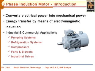
3 Phase Induction Motor - Introduction
• Converts electrical power into mechanical power
• Energy transfer by means of electromagnetic
induction
• Industrial & Commercial Applications
Pumping Systems
Refrigeration Systems
Compressors
Fans & Blowers
Industrial Drives
2. Rotating Magnetic Field
• 3 phase supply is given to a balanced 3 phase winding.
• 3 alternating magnetic fluxes displaced mutually at 120
o
is
produced.
240)t(sinφφ
120)t(sinφφ
tsinφφ
maxB
maxY
maxR
−=
−=
=
ω
ω
ω
3. Considering different instances of
time:
(i) At wt = 0
o
The instantaneous fluxes are
The resultant magnetic flux is
1.5 times peak value and
Acting at 90
o
to axis of reference.
maxB
maxY
R
φ866.0φ
φ866.0φ
0φ
+=
−=
=
4. (ii) At wt = 60
o
The instantaneous fluxes are
The resultant magnetic flux is
1.5 times peak value and acting
at 30
o
to axis of reference.
i.e., rotated by 60
o
w.r.t. previous angle
0φ
φ866.0φ
φ866.0φ
B
maxY
maxR
=
−=
+=
5. Similarly if various instances are considered upto 360
o
, it is seen
that the resultant always has a magnitude of 1.5 times peak
value and pointing in a direction at the angle of
consideration.
For every 360
o
, the resultant magnetic field completes one
rotation.
Inference:
When 3 phase currents flow in a balanced 3 phase winding, a
rotating magnetic field is created which has constant
magnitude, but rotates in synchronism with supply
frequency.
This speed of rotating magnetic field is called SYNCHRONOUS SPEED
P
f
NS
120
=
6. 101 / 102 Basic Electrical Technology Dept of E & E, MIT Manipal
Classification
• Construction
Squirrel Cage, Slip Ring
• Connection
Stator : Star, Delta
Rotor : Cage, Wound
• Application
Constant Power, Constant Torque, Constant Speed,
Variable Torque - Variable Speed
7. 101 / 102 Basic Electrical Technology Dept of E & E, MIT Manipal
Cross Sectional View
Terminal Box
Outer Frame
Stator
Cage Rotor
Shaft
Ball Bearings
Supporting Base
8. 101 / 102 Basic Electrical Technology Dept of E & E, MIT Manipal
Construction – Stator
• Stator frame: Cast Iron, Mechanical Support to stator core
• Stator core: Stack of cylindrical steel laminations
• Stator Slots: Inner periphery, Windings
Slots
Stator Conductors
Laminations
Outer frame
Stator Core
Stator Slots
Stator
windings
9. 101 / 102 Basic Electrical Technology Dept of E & E, MIT Manipal
Construction – Rotor
• Types on the basis of rotor construction
Squirrel Cage Rotor
Slip Ring Rotor
• Cylindrical Laminated core
• Slots cutout on outer periphery
• Conductors placed in slots
10. 101 / 102 Basic Electrical Technology Dept of E & E, MIT Manipal
Construction – Squirrel cage Rotor
• Skewed arrangement
• Copper or Aluminum Bars
• Conductors shorted by end rings
• Closed rotor circuit
Rotor
bars
End rings
11. 101 / 102 Basic Electrical Technology Dept of E & E, MIT Manipal
Construction – Slip ring rotor
• One end of Rotor conductors connected to each other (Star)
Rotor
External resistance
Shaft
• Other ends connected to slip rings
• Slip rings in contact with brushes
• Brushes connected to external resistance
Slip rings
Rotor
Conductors
Brush
12. Representation
101 / 102 Basic Electrical Technology Dept of E & E, MIT Manipal L1 – 15
3Ø Supply
Stator Core
Stator Slots
Stator conductors
Rotor conductors
Rotor Slots
Rotor CoreShaft