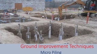
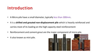
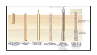
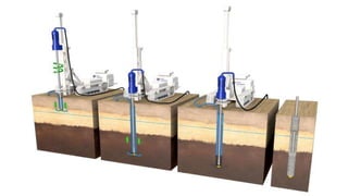
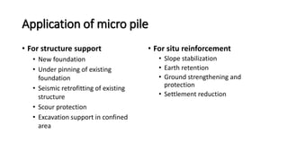
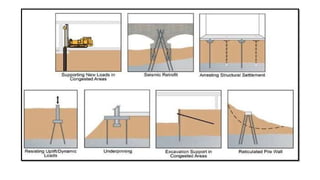
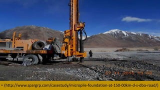
Ground Improvement Techniques
Micro Piling
History
• Micro-piles were conceived in Italy in the early 1950s,
• In response to the demand for innovative techniques for
underpinning historic buildings and monuments that had sustained
damage during World War II.
• It is used to support foundation to resist static and seismic loading
conditions, and as in-situ reinforcements for slope and excavation
stability.
Introduction
• A Micro pile have a small diameter, typically less than 300mm.
• It is a drilled and grouted non-displacement pile which is heavily reinforced and
carries most of its loading on the high capacity steel reinforcement
• Reinforcement and cement grout are the major component of micro pile.
• It also known as mini pile.
Favorable use of Micropile
• Hard strata is available at higher depth
• Damaged structure
• Hilly area
• Uneven settlement
• Space is less
• Excavation support
Classification
• Based on Design Criteria/Application
• Based on Construction
Based on Design Criteria/Application
1. Takes directly applied load
2. Provide reinforcement to the soil to
resist load.
Based on Construction type
1. Type A: Gravity Grout
2. Type B: Pressure through Casing
3. Type C: Single Global Post Grout
4. Type D: Multiple Repeatable Post Grout
Type A: Gravity Grout
• Gravity head only using sand-cement motors or neat cement
Type B: Pressure through Casing
• Cement grout is placed into the hole as the temporary steel casing
is with drawn.
• Injection pressures varies from 0.5 to 1.0 MPa. The pressure is
limited to avoid fracturing of the surrounding ground.
Type C: Single Global Post Grout
This is done in two step process:
• As of Type A
• Prior to hardening of the primary grout, similar grouts injected one
time via a sleeve grout pipe at pressure of at least 1.0MPa.
Type D: Multiple Repeatable Post Grout
This is done in two step process:
• As of Type A
• Prior to hardening of the primary grout, similar grouts injected one
time via a sleeve grout pipe at pressure of at 2.0 to 8.0MPa
Construction of micro pile
• Following step are carried out for construction of micro pile.
 Drilling and/or installation of temporary casing
 Remove inner drilling bit rod.
 Placing reinforcement and grouting by tremie.
 Remove temporary casing, inject further grout under pressure.
 Complete pile (casing may be left in place of compressible stratum)
Application of micro pile
• For structure support
• New foundation
• Under pinning of existing
foundation
• Seismic retrofitting of existing
structure
• Scour protection
• Excavation support in confined
area
• For situ reinforcement
• Slope stabilization
• Earth retention
• Ground strengthening and
protection
• Settlement reduction
Advantages of micro pile
• It used to underpin the existing structure where need of minimum
vibration.
• It can be easily laid where low head room is constraint.
• It can be installed at any angle.
• It offers practical and cost effective solution to costly alternative pile
system.
• Not require large access road or drilling platforms.
Case Study
KM 150.00 D-S-DBO Road
• The site at KM 150.00 is a deserted zone at elevation of 14500 feet with
glacier valleys and during summer season glacier melts which increases the
water level of Shyok River and damages the road which ultimately leads to
difficulty in transportation.
• The site located along hilly terrain, a highly remote area where accessibility is
very hard and climatic conditions are very harsh for humans.
• Government of India had tried various techniques for the foundation purpose
of the bridge such as deep (well, pile, etc.) and shallow foundations (open
cast foundation).
• Well foundation is not suitable due to higher water level
• Due to requirement of mobilization of heavy machinery pile foundation is not
feasible
• In case of shallow foundation the concrete is not setting due to the presence
of high water table, dewatering is required continuously which is not
considered to be a good option.
Site Location
Proposed Site Like this
Solution- (Micro pile)
• The company Spar Geo planned to construct 42 micro-piles as a
foundation each for 9 in river piers and 2 abutments. Each micro-pile
will have 273 mm diameter socketed 21 meters into soil.
• Grouting will be carried out using cement (53 grade OPC) with
addition of 1% special admixture of the total weight of cement to
increase the strength of grout mix with the help of double packer for
1.5 m section which helps to maintain almost a uniform thickness of
grout along the length.
• The pile testing will be conducted for vertical and lateral load up to
two times of designed load as per IS: 2911 (part 4).
• (http://www.spargrp.com/casestudy/micropile-foundation-at-150-00km-d-s-dbo-road/)
Inclined Piling
Pile Load Test
Preperd b : Thaiyam Sameer

Micropile

  • 1.
  • 2.
    History • Micro-piles wereconceived in Italy in the early 1950s, • In response to the demand for innovative techniques for underpinning historic buildings and monuments that had sustained damage during World War II. • It is used to support foundation to resist static and seismic loading conditions, and as in-situ reinforcements for slope and excavation stability.
  • 3.
    Introduction • A Micropile have a small diameter, typically less than 300mm. • It is a drilled and grouted non-displacement pile which is heavily reinforced and carries most of its loading on the high capacity steel reinforcement • Reinforcement and cement grout are the major component of micro pile. • It also known as mini pile.
  • 4.
    Favorable use ofMicropile • Hard strata is available at higher depth • Damaged structure • Hilly area • Uneven settlement • Space is less • Excavation support
  • 6.
    Classification • Based onDesign Criteria/Application • Based on Construction
  • 7.
    Based on DesignCriteria/Application 1. Takes directly applied load 2. Provide reinforcement to the soil to resist load.
  • 8.
    Based on Constructiontype 1. Type A: Gravity Grout 2. Type B: Pressure through Casing 3. Type C: Single Global Post Grout 4. Type D: Multiple Repeatable Post Grout
  • 9.
    Type A: GravityGrout • Gravity head only using sand-cement motors or neat cement Type B: Pressure through Casing • Cement grout is placed into the hole as the temporary steel casing is with drawn. • Injection pressures varies from 0.5 to 1.0 MPa. The pressure is limited to avoid fracturing of the surrounding ground. Type C: Single Global Post Grout This is done in two step process: • As of Type A • Prior to hardening of the primary grout, similar grouts injected one time via a sleeve grout pipe at pressure of at least 1.0MPa. Type D: Multiple Repeatable Post Grout This is done in two step process: • As of Type A • Prior to hardening of the primary grout, similar grouts injected one time via a sleeve grout pipe at pressure of at 2.0 to 8.0MPa
  • 11.
    Construction of micropile • Following step are carried out for construction of micro pile.  Drilling and/or installation of temporary casing  Remove inner drilling bit rod.  Placing reinforcement and grouting by tremie.  Remove temporary casing, inject further grout under pressure.  Complete pile (casing may be left in place of compressible stratum)
  • 14.
    Application of micropile • For structure support • New foundation • Under pinning of existing foundation • Seismic retrofitting of existing structure • Scour protection • Excavation support in confined area • For situ reinforcement • Slope stabilization • Earth retention • Ground strengthening and protection • Settlement reduction
  • 16.
    Advantages of micropile • It used to underpin the existing structure where need of minimum vibration. • It can be easily laid where low head room is constraint. • It can be installed at any angle. • It offers practical and cost effective solution to costly alternative pile system. • Not require large access road or drilling platforms.
  • 17.
    Case Study KM 150.00D-S-DBO Road • The site at KM 150.00 is a deserted zone at elevation of 14500 feet with glacier valleys and during summer season glacier melts which increases the water level of Shyok River and damages the road which ultimately leads to difficulty in transportation. • The site located along hilly terrain, a highly remote area where accessibility is very hard and climatic conditions are very harsh for humans. • Government of India had tried various techniques for the foundation purpose of the bridge such as deep (well, pile, etc.) and shallow foundations (open cast foundation). • Well foundation is not suitable due to higher water level • Due to requirement of mobilization of heavy machinery pile foundation is not feasible • In case of shallow foundation the concrete is not setting due to the presence of high water table, dewatering is required continuously which is not considered to be a good option.
  • 18.
  • 19.
  • 20.
    Solution- (Micro pile) •The company Spar Geo planned to construct 42 micro-piles as a foundation each for 9 in river piers and 2 abutments. Each micro-pile will have 273 mm diameter socketed 21 meters into soil. • Grouting will be carried out using cement (53 grade OPC) with addition of 1% special admixture of the total weight of cement to increase the strength of grout mix with the help of double packer for 1.5 m section which helps to maintain almost a uniform thickness of grout along the length. • The pile testing will be conducted for vertical and lateral load up to two times of designed load as per IS: 2911 (part 4).
  • 21.
  • 23.
  • 24.
  • 25.
    Preperd b :Thaiyam Sameer