![Overview of Boiler Operations
• Boilers are being used since 18th century
• Applications range from:
small hot water/steam
applications in
domestic/industrial use
large scale steam
production for power
generation
• Improvements in the quality of steam produced for
industrial applications
A couple of Bars Pressure
& a few 100’s °C
Temperature
(Saturated Steam)
~ 200-300 Bars pressure &
600 °C Temperature
(Superheated Steam)
[Large power generation
systems]](https://image.slidesharecdn.com/combustiontheorylecture12combustioninboilers-140225185939-phpapp01/85/combustion-in-boilers-3-320.jpg)
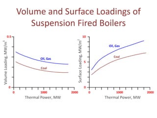
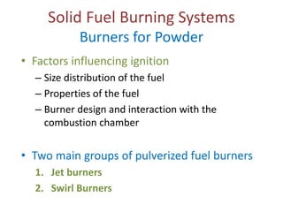
![Estimation of the Shape & Size of a
Combustion Chamber
• Useful criteria:
– Cross sectional surface loading QC = Qfuel/Ac [MW/m2]
– Volumetric Loading QV = Qfuel/V [MW/m3]
Where
AC – Cross sectional area of the furnace [m2]
V – volume of furnace [m3]
Qfuel – fuel power [MW]; This is related to electrical power Qe by
Qe = Qfuel · ηboiler · ηcycle
(ηboiler -Boiler efficiency; ηcycle- efficiency of the thermodynamic cycle)
• At a given air excess,
– QC - associated with cross sectional average gas velocity
– QV - connected to gas residence time](https://image.slidesharecdn.com/combustiontheorylecture12combustioninboilers-140225185939-phpapp01/85/combustion-in-boilers-10-320.jpg)

This lecture provided an overview of combustion in boilers including general boiler designs, applications of different boiler configurations, types of fuels used and related combustion systems, burner designs, and emission control methods. Key topics covered included heat balances and transfers, excess air calculations, sizing of combustion chambers, gas, liquid, and solid fuel burning systems, and techniques for reducing emissions like NOx, CO2, and particulate matter.


