Downloaded 1,269 times
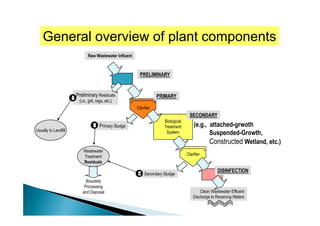
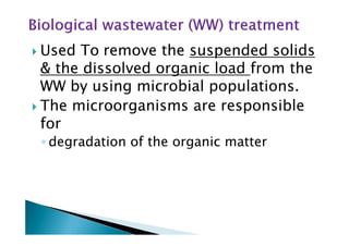
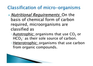
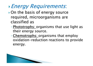
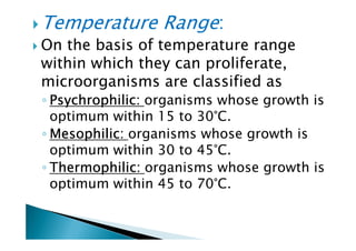
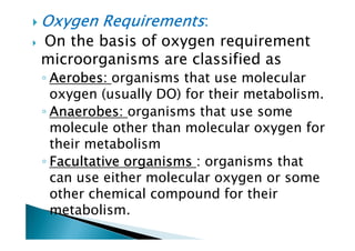
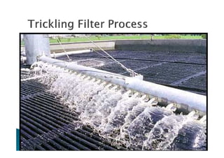
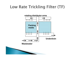
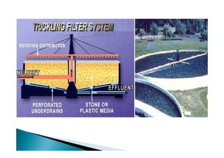
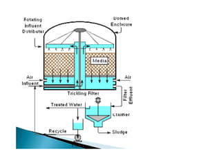
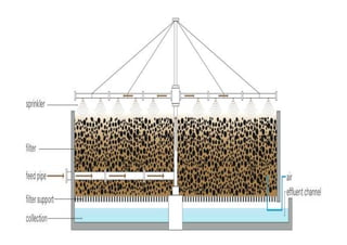

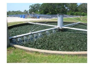

The document provides an in-depth overview of wastewater treatment processes, particularly focusing on biological treatment systems like trickling filters and their components. It categorizes microorganisms based on their nutritional, energy, temperature, and oxygen requirements, and discusses the mechanics and design considerations of trickling filters along with their advantages and disadvantages. Key parameters for optimal filter operation, including loading rates and material properties, are also detailed.