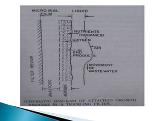
SlideShare a Scribd company logo
There are 3 major biological treatment
techniques:
1. Attached growth process(Fixed film process).
2. Suspended growth process.
3. Combined process.
In this process micro organisms are responsible
for conversion of organic matter present in waste
water to gases and cell tissues are attached to
some inert medium such as rock, slag, ceramic
or plastic material.
This process include:
1.Intermittent sand filters
2.Trickling filters 3.Rotating biological
contactors
4.Packed bed reactors 5.Anaerobic lagoons.
6.Fixed film denitrification. 7. Contact beds
In this process micro organisms are responsible
for conversion of organic matter present in waste
water to gases and cell tissues are maintained in
suspension within the liquid in the reactor by
employing either natural or mechanical mixing.
This process include:
1.Activated sludge process. 2.Aerated lagoons.
3.Sludge digestion system.
4.Suspended growth nitrification &
denitrification
This process includes both attached growth
and suspended growth process.
This process include :
1.Trickling filter, activated sludge.
2.Activated sludge, trickling filter.
3.Faculative lagoons.
1. Intermittent sand filter
• Consists of a layer of sand with an effective size of 0.2 – 0.5mm
• Sewage effluent from primary clarifiers is applied by means of a
dosing tank and siphon
• The effluent then flows on the surface of sand bed
• For efficient drainage a layer of 15cm – 30cm depth of gravel is
provided at the bottom of sand layer
• To carry off the effluent open jointed drainage pipes are laid in
the gravel layer
• Generally rectangular in plan
• Usually 3 to 4 beds are provided
Working
• Sewage effluent is applied intermittently and flooding is done
from 5 to 10 cm in depth after an interval of 24 hrs
• The effluent then percolates through the sand bed during which
the suspended organic matters get arrested in the voids of top
sand
• During the rest period the trapped organic matter is acted upon
by aerobic bacteria
• The effluent from the intermittent filter is quite clear containing
SS less than 10ppm, also BOD less than 5ppm
• Inorder to maintain the efficiency, the topmost layer of depth
25mm should be raked at regular intervals to breakup the
materials caught up in the top part of filter
• The sand should be renewed from time to time
ADVANTAGES
1. Effluent is of better quality, more clean and stable
2. No trouble of odour
3. Operation is very simple
4. Small head is required
5. No secondary sludge which is to be disposed
DISADVANTAGES
1. Rate of filtration hence that of loading is very small, hence
cannot be used for medium/ bigger size plants
2. They require large area and large quantity of sand
3. Construction is costly
2. CONTACT BEDS
• Similar to intermittent filters in construction except that the filtering media
is very coarse consisting of ballast of 20 to 50mm
• It is a water tight tank of masonry walls of rectangular shape
• Depth- 1- 1.8 m
• Generally below ground level and are lined with water tight cement plaster
or concrete
OPERATION
1. Filling- the tank is slowly filled with sewage (1-2hrs) through the dosing
tank. Depth of sewage may be 5-10cm over the top of bed.
2. Contact– sewage retained for 2hrs, during which organic impurities come
contact with bacterial film covering the filter media
3. Emptying- Sewage is withdrawn slowly through outlet (1-2hrs)
4. Oxidation– tank is then allowed to stand empty for 4-6hrs, during this
period atmospheric air enters into the media, resulting in the oxidation of
organic matters
• Effluent received is turbid and high in bacterial content
• 85-95% of SS, 60-80% of organic matter and 50 -75% of bacteria
are removed
ADVANTAGES
1. Can work under small heads
2. No fly nuisence
3. Problem of odour is much less
DISADVANTAGES
1. Rate of loading is much less
2. Large areas of land is required
3. Intermittand operation requires continuous attendance
4. Cost is more
3. TRICKLING FILTERS
• Also known as percolating filters/ sprinkling filters
• Operation is continuous and allow constant
aeration
• Types
On the basis of hydraulic and organic loading rates,
divided in to 2
1) Low rate filters 2) High rate filters
Types Hydraulic loading m3/d/m2 Organic loading
g/d/m3
Low rate filters 1-4 80-320
High rate filters 10-30 (including re circulation) 500-1000 (excluding
re circulation)
CONSTRUCTION:
It consist of mainly four parts:
1.water tight holding tank.
2.Distribution system.
3.Filter media.
4.Underdrainage system.
 The tank is either
1) rectangular or square- if fixed nozzles are used
and
2) circular in shape- if rotary distributors are used.
 As rotary distributors are more reliable & easy to
maintain and operate. So circular shape is most
commonly used.
 The walls are either masonry or concrete walls
 The walls are constructed such that they should
withstand the pressure exerted by sewage from
inside.
 The walls are made water tight.
 The under drain system is supported by a floor
which slopes to a collection channel.
 It also consists a filter media which should have high
specific surface area, high percent void space,
resistance to abrasion & insoluble in sewage water.
1. Filter media
• The most common filter media of trickling filters i. crushed rock, but large
gravel anthracite coal, blast furnace slag, broken bricks, clinker, cinder
ceramic and other such materials can also be used.
• must be weather-resistant and strong enough.
• Before filling the media, it must be washed with water and dried to remove
the dirts and other impurities.
• The size of the media should be between 30 mm to 80 mm.
Filter Depth:
• In high rate filters, the depth of tank varies from 1.0 to 1.8 metres in high
rate filters and in low rate filters from 2.0 to 3.0 metres.
2. Under drainage system
• Purpose is to- carry away the liquid effluent and to distribute air through
bed
• They are formed of precast vitrified clay or concrete blocks with perforated
cover or may be insitu with concrete o and covered with perforated pre cast
concrete slabs
• Floor is given a slope of about 1 in 100 to 1 in 50 during its construction,
towards the drains, for the collection of the treated sewage.
• The compressed air is also passed through these under-drainage lines.
3. Filter floor
• Should be strong enough to support the under drainage system
• Generally reinforced cement concrete slab of 10-15cm thick
used
• Slope towards collecting channel is 0.5-5%
4. Filter walls
• Either of fully plastered stone or brick masonry or of reinforced
concrete
5. Ventilation
• Adequate natural ventilation is induced by the difference in
temperature of air and sewage
• The air displacement is at the rate of about 0.3m3/s/m2 where
the difference of temperature is about 6℃
• Adequate natural ventilation can be ensured by proper design
of under drains and effluent channels
The sewage is allowed to sprinkle over filter media
through nozzles or rotary distributors.
The biological purification is mainly done by
aerobic bacteria which form a bacterial film known
as biofilm or slime layer around filter media.
The colour of this film is blackish, greenish and
yellowish
Apart from bacteria it consists of fungi, algae,
lichens, protozoa etc
This biofilm layer is aerobic only upto a depth of
0.1 to 0.2mm and remaining part is anaerobic.
The organic matter is degraded by aerobic micro
organisms on the outer portion of biofilm.
The food concentration is high at the outer surface
of biofilm hence the growth of micro organisms is
more at the outer surface of the biofilm.
The most diffused oxygen is consumed by micro
organism at the outer surface before it reaches to
the depth. Hence the anaerobic environment is
developed near the inner surface of the biofilm.
Eventually there is scouring of slime layer due to
flowing liquid and fresh slime layer begins to grow
on the media.
This phenomenon of scouring of slime is called
sloughing or unloading of the filter.
The trickling filter is always preceded by primary
sedimentation with skimming devices to remove the
scum.
The effluent from the filter is then taken to secondary
sedimentation tanks for settling out organic solids
oxidised while passing through filter.
ADVANTAGES
1. Effluent obtained is highly nitrified and stabilised
2. Can remove 80% SS and about 75-80% BOD
3. Rate of filter loading is high, hence require less space
4. Working is simple and cheap and does not require skilled
supervision
5. They are self cleansing
6. As it contains less mechanical equipments mechanical wear
and tear is small
DISADVANTAGES
1. Loss of head is high
2. Construction cost is high
3. Require large area
4. Final settlement in humus tank is necessary
5. Odour and fly nuisance
SUSPENDED GROWTH PROCESS
Activated sludge process (ASP)
• The activated sludge process is a type of biological wastewater
treatment process for treating sewage or industrial
wastewaters using aeration and a biological floc composed of bacteria
and protozoa.
• It uses air (or oxygen) and microorganisms to biologically oxidize organic
pollutants, producing a waste sludge (or floc) containing the oxidized
material.
• Activated sludge is the sludge with aerobic micro organisms, which is
obtained by settling sewage in presence of abundant oxygen
• ASP is based on providing intimate contact between the sewage and
biological active sludge
• Such sludge is developed initially by prolonged aeration under conditions
which favour the growth of organisms
ASP have three main components:
an aeration tank that serves as a bio reactor;
a settling tank for separating AS solids and treated waste
water; and
a return activated sludge (RAS) equipment that transfers
settled AS from the clarifier to the aeration tank's influent.
• The activated sludge process begins with an aeration tank
where air (or oxygen) is injected into the waste water.
• This is followed by a settling tank to allow the biological flocs
(the sludge blanket) to settle, thus separating the biological
sludge from the clear treated water.
• Part of the waste sludge is recycled to the aeration tank and the
remaining waste sludge is removed for further treatment and
ultimate disposal.
PROCESS
1. The effluent from the primary settling tank is mixed with a dose
of activated sludge and is aerated in an aeration tank for a
period of some hours
2. During aeration micro organisms multiply by assimilating part
of organic matter
3. The biological mass generated consists of bacteria, protozoa,
rotifers etc
4. The bio mass is flocculant and quick settling
5. It is separated from aerated sewage in secondary settling tank
and a part is recycled continuously into the aeration tank
6. The mixture of recycled sludge and sewage in the aeration tank
is referred as mixed liquor
AERATION UNITS
1. Diffused aeration- compressed air is blown through sewage in
aeration tanks through submerged diffusers or nozzles
2. Mechanical aeration- using mechanical surface aerators which
consists of large diameter impeller plates revolving on vertical
shaft
3. Combined system- in this diffused air aeration and mechanical
aeration are combined in a single unit. Aeration is done by
compressed air using air diffusers placed at the bottom and the
agitation of sewage is carried out by means of mechanical
paddles
ADVANTAGES
1. Clear and non putrescible effluent
2. No odour problem
3. No fly nuisance
4. Highly efficient- 90% removal of SS, BOD and bacteria
5. Low cost of installation
6. Smaller area required
DISADVANTAGES
1. Very sensitive to variations in the quality of sewage (in respect
of industrial wastes)
2. High cost of operation
3. Constant skilled supervision required
4. Uncertainty of expected results under all conditions
5. Large quantity of sludge is produced which is difficult to
dewater
THANKYOU
trickling filters.pptx

More Related Content

Similar to trickling filters.pptx

Trickling filters ppt.
Trickling filters ppt.Trickling filters ppt.
Trickling filters ppt.
Muttu Hugar
 
L 20 High rate Trickling Filter
L 20 High rate Trickling FilterL 20 High rate Trickling Filter
L 20 High rate Trickling Filter
Dr. shrikant jahagirdar
 
TREATMENT TECHNOLOGIES A COMPARISON
TREATMENT TECHNOLOGIES  A COMPARISON TREATMENT TECHNOLOGIES  A COMPARISON
TREATMENT TECHNOLOGIES A COMPARISON
virgo_az
 
Environmental Health & Housing-2023 4th yr ANMC.pptx
Environmental Health & Housing-2023 4th yr ANMC.pptxEnvironmental Health & Housing-2023 4th yr ANMC.pptx
Environmental Health & Housing-2023 4th yr ANMC.pptx
Rizwan Saeed
 
Tertiary waste management ppt
Tertiary waste management pptTertiary waste management ppt
Tertiary waste management ppt
Rajatsingh
 
WATER PURIFICATION
WATER PURIFICATIONWATER PURIFICATION
WATER PURIFICATION
Suraj Dhara
 
Building Services
Building ServicesBuilding Services
Building Services
Nitha KJ
 
Filtration Process in Water Treatment.ppt
Filtration Process in Water Treatment.pptFiltration Process in Water Treatment.ppt
Filtration Process in Water Treatment.ppt
Vishal Chaudhari
 
Sewage treatment-system-8
Sewage treatment-system-8Sewage treatment-system-8
Sewage treatment-system-8
cheeweishan
 
ADVANCED METHOD FOR WASTE WATER TREATMENT.pptx
ADVANCED METHOD FOR WASTE WATER TREATMENT.pptxADVANCED METHOD FOR WASTE WATER TREATMENT.pptx
ADVANCED METHOD FOR WASTE WATER TREATMENT.pptx
Sakshi Patil
 
Sewage and liquid waste management
Sewage and liquid waste management Sewage and liquid waste management
Sewage and liquid waste management
bayapreddy
 
Sewage treatment-system
Sewage treatment-systemSewage treatment-system
Sewage treatment-system
April Yoona
 
waterpurificationrizwan-160310070141_(1).pptx
waterpurificationrizwan-160310070141_(1).pptxwaterpurificationrizwan-160310070141_(1).pptx
waterpurificationrizwan-160310070141_(1).pptx
Geeta Sunilkumar
 
Vermifiltration
VermifiltrationVermifiltration
WASTE WATER TREATMENT
WASTE WATER TREATMENTWASTE WATER TREATMENT
WASTE WATER TREATMENT
Sheama Farheen Savanur
 
L 24 filtration
L 24 filtrationL 24 filtration
L 24 filtration
Dr. shrikant jahagirdar
 
spray dryer.pptx
spray dryer.pptxspray dryer.pptx
spray dryer.pptx
DIVYASINGH992260
 
MODERN SEWAGE TREATMENT.ppt
MODERN SEWAGE TREATMENT.pptMODERN SEWAGE TREATMENT.ppt
MODERN SEWAGE TREATMENT.ppt
AnchuRNath
 
MODERN SEWAGE TREATMENT.ppt
MODERN SEWAGE TREATMENT.pptMODERN SEWAGE TREATMENT.ppt
MODERN SEWAGE TREATMENT.ppt
AnchuRNath
 
MODERN SEWAGE TREATMENT.ppt
MODERN SEWAGE TREATMENT.pptMODERN SEWAGE TREATMENT.ppt
MODERN SEWAGE TREATMENT.ppt
AnchuRNath
 

Similar to trickling filters.pptx (20)

Trickling filters ppt.
Trickling filters ppt.Trickling filters ppt.
Trickling filters ppt.
 
L 20 High rate Trickling Filter
L 20 High rate Trickling FilterL 20 High rate Trickling Filter
L 20 High rate Trickling Filter
 
TREATMENT TECHNOLOGIES A COMPARISON
TREATMENT TECHNOLOGIES  A COMPARISON TREATMENT TECHNOLOGIES  A COMPARISON
TREATMENT TECHNOLOGIES A COMPARISON
 
Environmental Health & Housing-2023 4th yr ANMC.pptx
Environmental Health & Housing-2023 4th yr ANMC.pptxEnvironmental Health & Housing-2023 4th yr ANMC.pptx
Environmental Health & Housing-2023 4th yr ANMC.pptx
 
Tertiary waste management ppt
Tertiary waste management pptTertiary waste management ppt
Tertiary waste management ppt
 
WATER PURIFICATION
WATER PURIFICATIONWATER PURIFICATION
WATER PURIFICATION
 
Building Services
Building ServicesBuilding Services
Building Services
 
Filtration Process in Water Treatment.ppt
Filtration Process in Water Treatment.pptFiltration Process in Water Treatment.ppt
Filtration Process in Water Treatment.ppt
 
Sewage treatment-system-8
Sewage treatment-system-8Sewage treatment-system-8
Sewage treatment-system-8
 
ADVANCED METHOD FOR WASTE WATER TREATMENT.pptx
ADVANCED METHOD FOR WASTE WATER TREATMENT.pptxADVANCED METHOD FOR WASTE WATER TREATMENT.pptx
ADVANCED METHOD FOR WASTE WATER TREATMENT.pptx
 
Sewage and liquid waste management
Sewage and liquid waste management Sewage and liquid waste management
Sewage and liquid waste management
 
Sewage treatment-system
Sewage treatment-systemSewage treatment-system
Sewage treatment-system
 
waterpurificationrizwan-160310070141_(1).pptx
waterpurificationrizwan-160310070141_(1).pptxwaterpurificationrizwan-160310070141_(1).pptx
waterpurificationrizwan-160310070141_(1).pptx
 
Vermifiltration
VermifiltrationVermifiltration
Vermifiltration
 
WASTE WATER TREATMENT
WASTE WATER TREATMENTWASTE WATER TREATMENT
WASTE WATER TREATMENT
 
L 24 filtration
L 24 filtrationL 24 filtration
L 24 filtration
 
spray dryer.pptx
spray dryer.pptxspray dryer.pptx
spray dryer.pptx
 
MODERN SEWAGE TREATMENT.ppt
MODERN SEWAGE TREATMENT.pptMODERN SEWAGE TREATMENT.ppt
MODERN SEWAGE TREATMENT.ppt
 
MODERN SEWAGE TREATMENT.ppt
MODERN SEWAGE TREATMENT.pptMODERN SEWAGE TREATMENT.ppt
MODERN SEWAGE TREATMENT.ppt
 
MODERN SEWAGE TREATMENT.ppt
MODERN SEWAGE TREATMENT.pptMODERN SEWAGE TREATMENT.ppt
MODERN SEWAGE TREATMENT.ppt
 

More from GeethuShanmughan

preliminary treatment.pptx
preliminary treatment.pptxpreliminary treatment.pptx
preliminary treatment.pptx
GeethuShanmughan
 
Subsurface water Control methods (1).pptx
Subsurface water Control methods (1).pptxSubsurface water Control methods (1).pptx
Subsurface water Control methods (1).pptx
GeethuShanmughan
 
Sedimentation
SedimentationSedimentation
Sedimentation
GeethuShanmughan
 
soil erosion and conservation
 soil erosion and conservation soil erosion and conservation
soil erosion and conservation
GeethuShanmughan
 
Flood & Tsunami.pptx
Flood & Tsunami.pptxFlood & Tsunami.pptx
Flood & Tsunami.pptx
GeethuShanmughan
 
Cyclone.pptx
Cyclone.pptxCyclone.pptx
Cyclone.pptx
GeethuShanmughan
 

More from GeethuShanmughan (6)

preliminary treatment.pptx
preliminary treatment.pptxpreliminary treatment.pptx
preliminary treatment.pptx
 
Subsurface water Control methods (1).pptx
Subsurface water Control methods (1).pptxSubsurface water Control methods (1).pptx
Subsurface water Control methods (1).pptx
 
Sedimentation
SedimentationSedimentation
Sedimentation
 
soil erosion and conservation
 soil erosion and conservation soil erosion and conservation
soil erosion and conservation
 
Flood & Tsunami.pptx
Flood & Tsunami.pptxFlood & Tsunami.pptx
Flood & Tsunami.pptx
 
Cyclone.pptx
Cyclone.pptxCyclone.pptx
Cyclone.pptx
 

Recently uploaded

Standard Reomte Control Interface - Neometrix
Standard Reomte Control Interface - NeometrixStandard Reomte Control Interface - Neometrix
Standard Reomte Control Interface - Neometrix
Neometrix_Engineering_Pvt_Ltd
 
CME397 Surface Engineering- Professional Elective
CME397 Surface Engineering- Professional ElectiveCME397 Surface Engineering- Professional Elective
CME397 Surface Engineering- Professional Elective
karthi keyan
 
一比一原版(UofT毕业证)多伦多大学毕业证成绩单如何办理
一比一原版(UofT毕业证)多伦多大学毕业证成绩单如何办理一比一原版(UofT毕业证)多伦多大学毕业证成绩单如何办理
一比一原版(UofT毕业证)多伦多大学毕业证成绩单如何办理
ydteq
 
Immunizing Image Classifiers Against Localized Adversary Attacks
Immunizing Image Classifiers Against Localized Adversary AttacksImmunizing Image Classifiers Against Localized Adversary Attacks
Immunizing Image Classifiers Against Localized Adversary Attacks
gerogepatton
 
Design and Analysis of Algorithms-DP,Backtracking,Graphs,B&B
Design and Analysis of Algorithms-DP,Backtracking,Graphs,B&BDesign and Analysis of Algorithms-DP,Backtracking,Graphs,B&B
Design and Analysis of Algorithms-DP,Backtracking,Graphs,B&B
Sreedhar Chowdam
 
一比一原版(IIT毕业证)伊利诺伊理工大学毕业证成绩单专业办理
一比一原版(IIT毕业证)伊利诺伊理工大学毕业证成绩单专业办理一比一原版(IIT毕业证)伊利诺伊理工大学毕业证成绩单专业办理
一比一原版(IIT毕业证)伊利诺伊理工大学毕业证成绩单专业办理
zwunae
 
Final project report on grocery store management system..pdf
Final project report on grocery store management system..pdfFinal project report on grocery store management system..pdf
Final project report on grocery store management system..pdf
Kamal Acharya
 
NO1 Uk best vashikaran specialist in delhi vashikaran baba near me online vas...
NO1 Uk best vashikaran specialist in delhi vashikaran baba near me online vas...NO1 Uk best vashikaran specialist in delhi vashikaran baba near me online vas...
NO1 Uk best vashikaran specialist in delhi vashikaran baba near me online vas...
Amil Baba Dawood bangali
 
block diagram and signal flow graph representation
block diagram and signal flow graph representationblock diagram and signal flow graph representation
block diagram and signal flow graph representation
Divya Somashekar
 
Top 10 Oil and Gas Projects in Saudi Arabia 2024.pdf
Top 10 Oil and Gas Projects in Saudi Arabia 2024.pdfTop 10 Oil and Gas Projects in Saudi Arabia 2024.pdf
Top 10 Oil and Gas Projects in Saudi Arabia 2024.pdf
Teleport Manpower Consultant
 
Industrial Training at Shahjalal Fertilizer Company Limited (SFCL)
Industrial Training at Shahjalal Fertilizer Company Limited (SFCL)Industrial Training at Shahjalal Fertilizer Company Limited (SFCL)
Industrial Training at Shahjalal Fertilizer Company Limited (SFCL)
MdTanvirMahtab2
 
RAT: Retrieval Augmented Thoughts Elicit Context-Aware Reasoning in Long-Hori...
RAT: Retrieval Augmented Thoughts Elicit Context-Aware Reasoning in Long-Hori...RAT: Retrieval Augmented Thoughts Elicit Context-Aware Reasoning in Long-Hori...
RAT: Retrieval Augmented Thoughts Elicit Context-Aware Reasoning in Long-Hori...
thanhdowork
 
Heap Sort (SS).ppt FOR ENGINEERING GRADUATES, BCA, MCA, MTECH, BSC STUDENTS
Heap Sort (SS).ppt FOR ENGINEERING GRADUATES, BCA, MCA, MTECH, BSC STUDENTSHeap Sort (SS).ppt FOR ENGINEERING GRADUATES, BCA, MCA, MTECH, BSC STUDENTS
Heap Sort (SS).ppt FOR ENGINEERING GRADUATES, BCA, MCA, MTECH, BSC STUDENTS
Soumen Santra
 
road safety engineering r s e unit 3.pdf
road safety engineering  r s e unit 3.pdfroad safety engineering  r s e unit 3.pdf
road safety engineering r s e unit 3.pdf
VENKATESHvenky89705
 
AKS UNIVERSITY Satna Final Year Project By OM Hardaha.pdf
AKS UNIVERSITY Satna Final Year Project By OM Hardaha.pdfAKS UNIVERSITY Satna Final Year Project By OM Hardaha.pdf
AKS UNIVERSITY Satna Final Year Project By OM Hardaha.pdf
SamSarthak3
 
Recycled Concrete Aggregate in Construction Part III
Recycled Concrete Aggregate in Construction Part IIIRecycled Concrete Aggregate in Construction Part III
Recycled Concrete Aggregate in Construction Part III
Aditya Rajan Patra
 
Hybrid optimization of pumped hydro system and solar- Engr. Abdul-Azeez.pdf
Hybrid optimization of pumped hydro system and solar- Engr. Abdul-Azeez.pdfHybrid optimization of pumped hydro system and solar- Engr. Abdul-Azeez.pdf
Hybrid optimization of pumped hydro system and solar- Engr. Abdul-Azeez.pdf
fxintegritypublishin
 
ML for identifying fraud using open blockchain data.pptx
ML for identifying fraud using open blockchain data.pptxML for identifying fraud using open blockchain data.pptx
ML for identifying fraud using open blockchain data.pptx
Vijay Dialani, PhD
 
Cosmetic shop management system project report.pdf
Cosmetic shop management system project report.pdfCosmetic shop management system project report.pdf
Cosmetic shop management system project report.pdf
Kamal Acharya
 
CW RADAR, FMCW RADAR, FMCW ALTIMETER, AND THEIR PARAMETERS
CW RADAR, FMCW RADAR, FMCW ALTIMETER, AND THEIR PARAMETERSCW RADAR, FMCW RADAR, FMCW ALTIMETER, AND THEIR PARAMETERS
CW RADAR, FMCW RADAR, FMCW ALTIMETER, AND THEIR PARAMETERS
veerababupersonal22
 

Recently uploaded (20)

Standard Reomte Control Interface - Neometrix
Standard Reomte Control Interface - NeometrixStandard Reomte Control Interface - Neometrix
Standard Reomte Control Interface - Neometrix
 
CME397 Surface Engineering- Professional Elective
CME397 Surface Engineering- Professional ElectiveCME397 Surface Engineering- Professional Elective
CME397 Surface Engineering- Professional Elective
 
一比一原版(UofT毕业证)多伦多大学毕业证成绩单如何办理
一比一原版(UofT毕业证)多伦多大学毕业证成绩单如何办理一比一原版(UofT毕业证)多伦多大学毕业证成绩单如何办理
一比一原版(UofT毕业证)多伦多大学毕业证成绩单如何办理
 
Immunizing Image Classifiers Against Localized Adversary Attacks
Immunizing Image Classifiers Against Localized Adversary AttacksImmunizing Image Classifiers Against Localized Adversary Attacks
Immunizing Image Classifiers Against Localized Adversary Attacks
 
Design and Analysis of Algorithms-DP,Backtracking,Graphs,B&B
Design and Analysis of Algorithms-DP,Backtracking,Graphs,B&BDesign and Analysis of Algorithms-DP,Backtracking,Graphs,B&B
Design and Analysis of Algorithms-DP,Backtracking,Graphs,B&B
 
一比一原版(IIT毕业证)伊利诺伊理工大学毕业证成绩单专业办理
一比一原版(IIT毕业证)伊利诺伊理工大学毕业证成绩单专业办理一比一原版(IIT毕业证)伊利诺伊理工大学毕业证成绩单专业办理
一比一原版(IIT毕业证)伊利诺伊理工大学毕业证成绩单专业办理
 
Final project report on grocery store management system..pdf
Final project report on grocery store management system..pdfFinal project report on grocery store management system..pdf
Final project report on grocery store management system..pdf
 
NO1 Uk best vashikaran specialist in delhi vashikaran baba near me online vas...
NO1 Uk best vashikaran specialist in delhi vashikaran baba near me online vas...NO1 Uk best vashikaran specialist in delhi vashikaran baba near me online vas...
NO1 Uk best vashikaran specialist in delhi vashikaran baba near me online vas...
 
block diagram and signal flow graph representation
block diagram and signal flow graph representationblock diagram and signal flow graph representation
block diagram and signal flow graph representation
 
Top 10 Oil and Gas Projects in Saudi Arabia 2024.pdf
Top 10 Oil and Gas Projects in Saudi Arabia 2024.pdfTop 10 Oil and Gas Projects in Saudi Arabia 2024.pdf
Top 10 Oil and Gas Projects in Saudi Arabia 2024.pdf
 
Industrial Training at Shahjalal Fertilizer Company Limited (SFCL)
Industrial Training at Shahjalal Fertilizer Company Limited (SFCL)Industrial Training at Shahjalal Fertilizer Company Limited (SFCL)
Industrial Training at Shahjalal Fertilizer Company Limited (SFCL)
 
RAT: Retrieval Augmented Thoughts Elicit Context-Aware Reasoning in Long-Hori...
RAT: Retrieval Augmented Thoughts Elicit Context-Aware Reasoning in Long-Hori...RAT: Retrieval Augmented Thoughts Elicit Context-Aware Reasoning in Long-Hori...
RAT: Retrieval Augmented Thoughts Elicit Context-Aware Reasoning in Long-Hori...
 
Heap Sort (SS).ppt FOR ENGINEERING GRADUATES, BCA, MCA, MTECH, BSC STUDENTS
Heap Sort (SS).ppt FOR ENGINEERING GRADUATES, BCA, MCA, MTECH, BSC STUDENTSHeap Sort (SS).ppt FOR ENGINEERING GRADUATES, BCA, MCA, MTECH, BSC STUDENTS
Heap Sort (SS).ppt FOR ENGINEERING GRADUATES, BCA, MCA, MTECH, BSC STUDENTS
 
road safety engineering r s e unit 3.pdf
road safety engineering  r s e unit 3.pdfroad safety engineering  r s e unit 3.pdf
road safety engineering r s e unit 3.pdf
 
AKS UNIVERSITY Satna Final Year Project By OM Hardaha.pdf
AKS UNIVERSITY Satna Final Year Project By OM Hardaha.pdfAKS UNIVERSITY Satna Final Year Project By OM Hardaha.pdf
AKS UNIVERSITY Satna Final Year Project By OM Hardaha.pdf
 
Recycled Concrete Aggregate in Construction Part III
Recycled Concrete Aggregate in Construction Part IIIRecycled Concrete Aggregate in Construction Part III
Recycled Concrete Aggregate in Construction Part III
 
Hybrid optimization of pumped hydro system and solar- Engr. Abdul-Azeez.pdf
Hybrid optimization of pumped hydro system and solar- Engr. Abdul-Azeez.pdfHybrid optimization of pumped hydro system and solar- Engr. Abdul-Azeez.pdf
Hybrid optimization of pumped hydro system and solar- Engr. Abdul-Azeez.pdf
 
ML for identifying fraud using open blockchain data.pptx
ML for identifying fraud using open blockchain data.pptxML for identifying fraud using open blockchain data.pptx
ML for identifying fraud using open blockchain data.pptx
 
Cosmetic shop management system project report.pdf
Cosmetic shop management system project report.pdfCosmetic shop management system project report.pdf
Cosmetic shop management system project report.pdf
 
CW RADAR, FMCW RADAR, FMCW ALTIMETER, AND THEIR PARAMETERS
CW RADAR, FMCW RADAR, FMCW ALTIMETER, AND THEIR PARAMETERSCW RADAR, FMCW RADAR, FMCW ALTIMETER, AND THEIR PARAMETERS
CW RADAR, FMCW RADAR, FMCW ALTIMETER, AND THEIR PARAMETERS
 

trickling filters.pptx

  • 1. There are 3 major biological treatment techniques: 1. Attached growth process(Fixed film process). 2. Suspended growth process. 3. Combined process.
  • 2. In this process micro organisms are responsible for conversion of organic matter present in waste water to gases and cell tissues are attached to some inert medium such as rock, slag, ceramic or plastic material. This process include: 1.Intermittent sand filters 2.Trickling filters 3.Rotating biological contactors 4.Packed bed reactors 5.Anaerobic lagoons. 6.Fixed film denitrification. 7. Contact beds
  • 3. In this process micro organisms are responsible for conversion of organic matter present in waste water to gases and cell tissues are maintained in suspension within the liquid in the reactor by employing either natural or mechanical mixing. This process include: 1.Activated sludge process. 2.Aerated lagoons. 3.Sludge digestion system. 4.Suspended growth nitrification & denitrification
  • 4. This process includes both attached growth and suspended growth process. This process include : 1.Trickling filter, activated sludge. 2.Activated sludge, trickling filter. 3.Faculative lagoons.
  • 5. 1. Intermittent sand filter • Consists of a layer of sand with an effective size of 0.2 – 0.5mm • Sewage effluent from primary clarifiers is applied by means of a dosing tank and siphon • The effluent then flows on the surface of sand bed • For efficient drainage a layer of 15cm – 30cm depth of gravel is provided at the bottom of sand layer • To carry off the effluent open jointed drainage pipes are laid in the gravel layer • Generally rectangular in plan • Usually 3 to 4 beds are provided
  • 6. Working • Sewage effluent is applied intermittently and flooding is done from 5 to 10 cm in depth after an interval of 24 hrs • The effluent then percolates through the sand bed during which the suspended organic matters get arrested in the voids of top sand • During the rest period the trapped organic matter is acted upon by aerobic bacteria • The effluent from the intermittent filter is quite clear containing SS less than 10ppm, also BOD less than 5ppm • Inorder to maintain the efficiency, the topmost layer of depth 25mm should be raked at regular intervals to breakup the materials caught up in the top part of filter • The sand should be renewed from time to time
  • 7. ADVANTAGES 1. Effluent is of better quality, more clean and stable 2. No trouble of odour 3. Operation is very simple 4. Small head is required 5. No secondary sludge which is to be disposed DISADVANTAGES 1. Rate of filtration hence that of loading is very small, hence cannot be used for medium/ bigger size plants 2. They require large area and large quantity of sand 3. Construction is costly
  • 8.
  • 9. 2. CONTACT BEDS • Similar to intermittent filters in construction except that the filtering media is very coarse consisting of ballast of 20 to 50mm • It is a water tight tank of masonry walls of rectangular shape • Depth- 1- 1.8 m • Generally below ground level and are lined with water tight cement plaster or concrete OPERATION 1. Filling- the tank is slowly filled with sewage (1-2hrs) through the dosing tank. Depth of sewage may be 5-10cm over the top of bed. 2. Contact– sewage retained for 2hrs, during which organic impurities come contact with bacterial film covering the filter media 3. Emptying- Sewage is withdrawn slowly through outlet (1-2hrs) 4. Oxidation– tank is then allowed to stand empty for 4-6hrs, during this period atmospheric air enters into the media, resulting in the oxidation of organic matters
  • 10. • Effluent received is turbid and high in bacterial content • 85-95% of SS, 60-80% of organic matter and 50 -75% of bacteria are removed ADVANTAGES 1. Can work under small heads 2. No fly nuisence 3. Problem of odour is much less DISADVANTAGES 1. Rate of loading is much less 2. Large areas of land is required 3. Intermittand operation requires continuous attendance 4. Cost is more
  • 11.
  • 12. 3. TRICKLING FILTERS • Also known as percolating filters/ sprinkling filters • Operation is continuous and allow constant aeration • Types On the basis of hydraulic and organic loading rates, divided in to 2 1) Low rate filters 2) High rate filters Types Hydraulic loading m3/d/m2 Organic loading g/d/m3 Low rate filters 1-4 80-320 High rate filters 10-30 (including re circulation) 500-1000 (excluding re circulation)
  • 13. CONSTRUCTION: It consist of mainly four parts: 1.water tight holding tank. 2.Distribution system. 3.Filter media. 4.Underdrainage system.
  • 14.
  • 15.  The tank is either 1) rectangular or square- if fixed nozzles are used and 2) circular in shape- if rotary distributors are used.  As rotary distributors are more reliable & easy to maintain and operate. So circular shape is most commonly used.  The walls are either masonry or concrete walls  The walls are constructed such that they should withstand the pressure exerted by sewage from inside.  The walls are made water tight.
  • 16.  The under drain system is supported by a floor which slopes to a collection channel.  It also consists a filter media which should have high specific surface area, high percent void space, resistance to abrasion & insoluble in sewage water.
  • 17. 1. Filter media • The most common filter media of trickling filters i. crushed rock, but large gravel anthracite coal, blast furnace slag, broken bricks, clinker, cinder ceramic and other such materials can also be used. • must be weather-resistant and strong enough. • Before filling the media, it must be washed with water and dried to remove the dirts and other impurities. • The size of the media should be between 30 mm to 80 mm. Filter Depth: • In high rate filters, the depth of tank varies from 1.0 to 1.8 metres in high rate filters and in low rate filters from 2.0 to 3.0 metres. 2. Under drainage system • Purpose is to- carry away the liquid effluent and to distribute air through bed • They are formed of precast vitrified clay or concrete blocks with perforated cover or may be insitu with concrete o and covered with perforated pre cast concrete slabs • Floor is given a slope of about 1 in 100 to 1 in 50 during its construction, towards the drains, for the collection of the treated sewage. • The compressed air is also passed through these under-drainage lines.
  • 18. 3. Filter floor • Should be strong enough to support the under drainage system • Generally reinforced cement concrete slab of 10-15cm thick used • Slope towards collecting channel is 0.5-5% 4. Filter walls • Either of fully plastered stone or brick masonry or of reinforced concrete 5. Ventilation • Adequate natural ventilation is induced by the difference in temperature of air and sewage • The air displacement is at the rate of about 0.3m3/s/m2 where the difference of temperature is about 6℃ • Adequate natural ventilation can be ensured by proper design of under drains and effluent channels
  • 19. The sewage is allowed to sprinkle over filter media through nozzles or rotary distributors. The biological purification is mainly done by aerobic bacteria which form a bacterial film known as biofilm or slime layer around filter media. The colour of this film is blackish, greenish and yellowish Apart from bacteria it consists of fungi, algae, lichens, protozoa etc This biofilm layer is aerobic only upto a depth of 0.1 to 0.2mm and remaining part is anaerobic.
  • 20. The organic matter is degraded by aerobic micro organisms on the outer portion of biofilm. The food concentration is high at the outer surface of biofilm hence the growth of micro organisms is more at the outer surface of the biofilm. The most diffused oxygen is consumed by micro organism at the outer surface before it reaches to the depth. Hence the anaerobic environment is developed near the inner surface of the biofilm.
  • 21.
  • 22. Eventually there is scouring of slime layer due to flowing liquid and fresh slime layer begins to grow on the media. This phenomenon of scouring of slime is called sloughing or unloading of the filter. The trickling filter is always preceded by primary sedimentation with skimming devices to remove the scum. The effluent from the filter is then taken to secondary sedimentation tanks for settling out organic solids oxidised while passing through filter.
  • 23. ADVANTAGES 1. Effluent obtained is highly nitrified and stabilised 2. Can remove 80% SS and about 75-80% BOD 3. Rate of filter loading is high, hence require less space 4. Working is simple and cheap and does not require skilled supervision 5. They are self cleansing 6. As it contains less mechanical equipments mechanical wear and tear is small DISADVANTAGES 1. Loss of head is high 2. Construction cost is high 3. Require large area 4. Final settlement in humus tank is necessary 5. Odour and fly nuisance
  • 24. SUSPENDED GROWTH PROCESS Activated sludge process (ASP) • The activated sludge process is a type of biological wastewater treatment process for treating sewage or industrial wastewaters using aeration and a biological floc composed of bacteria and protozoa. • It uses air (or oxygen) and microorganisms to biologically oxidize organic pollutants, producing a waste sludge (or floc) containing the oxidized material. • Activated sludge is the sludge with aerobic micro organisms, which is obtained by settling sewage in presence of abundant oxygen • ASP is based on providing intimate contact between the sewage and biological active sludge • Such sludge is developed initially by prolonged aeration under conditions which favour the growth of organisms
  • 25. ASP have three main components: an aeration tank that serves as a bio reactor; a settling tank for separating AS solids and treated waste water; and a return activated sludge (RAS) equipment that transfers settled AS from the clarifier to the aeration tank's influent.
  • 26. • The activated sludge process begins with an aeration tank where air (or oxygen) is injected into the waste water. • This is followed by a settling tank to allow the biological flocs (the sludge blanket) to settle, thus separating the biological sludge from the clear treated water. • Part of the waste sludge is recycled to the aeration tank and the remaining waste sludge is removed for further treatment and ultimate disposal.
  • 27. PROCESS 1. The effluent from the primary settling tank is mixed with a dose of activated sludge and is aerated in an aeration tank for a period of some hours 2. During aeration micro organisms multiply by assimilating part of organic matter 3. The biological mass generated consists of bacteria, protozoa, rotifers etc 4. The bio mass is flocculant and quick settling 5. It is separated from aerated sewage in secondary settling tank and a part is recycled continuously into the aeration tank 6. The mixture of recycled sludge and sewage in the aeration tank is referred as mixed liquor
  • 28. AERATION UNITS 1. Diffused aeration- compressed air is blown through sewage in aeration tanks through submerged diffusers or nozzles 2. Mechanical aeration- using mechanical surface aerators which consists of large diameter impeller plates revolving on vertical shaft 3. Combined system- in this diffused air aeration and mechanical aeration are combined in a single unit. Aeration is done by compressed air using air diffusers placed at the bottom and the agitation of sewage is carried out by means of mechanical paddles
  • 29. ADVANTAGES 1. Clear and non putrescible effluent 2. No odour problem 3. No fly nuisance 4. Highly efficient- 90% removal of SS, BOD and bacteria 5. Low cost of installation 6. Smaller area required DISADVANTAGES 1. Very sensitive to variations in the quality of sewage (in respect of industrial wastes) 2. High cost of operation 3. Constant skilled supervision required 4. Uncertainty of expected results under all conditions 5. Large quantity of sludge is produced which is difficult to dewater