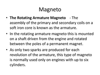
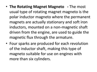
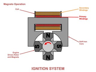
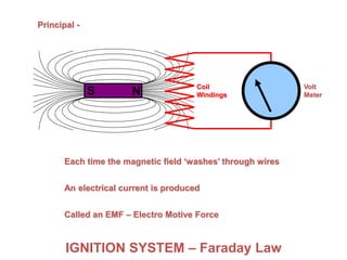
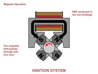
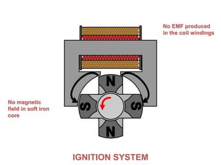
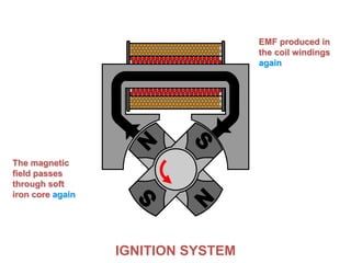
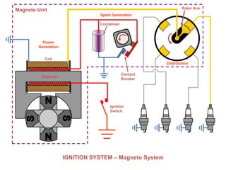
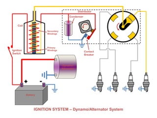
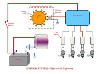
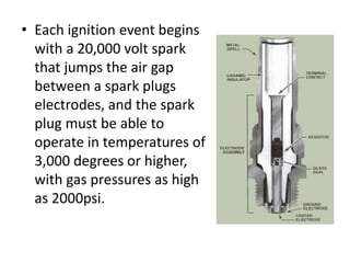
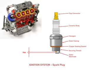
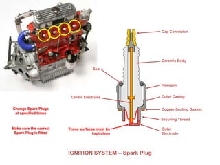
Piston Engine Propulsion
Ignition
Ignition in a piston engine requires:
• Spark plugs
• Magneto
• Condensers
• Distributor
• Contact breakers electronic systems
Magneto
• The Rotating Armature Magneto - The
assembly of the primary and secondary coils on a
soft iron core is known as the armature.
• In the rotating armature magneto this is mounted
on a shaft driven from the engine and rotated
between the poles of a permanent magnet.
• As only two sparks are produced for each
revolution of the armature, this type of magneto
is normally used only on engines with up to six
cylinders.
• The Rotating Magnet Magneto - The most
usual type of rotating magnet magneto is the
polar inductor magneto where the permanent
magnets are actually stationary and soft iron
inductors, mounted on a non-magnetic shaft
driven from the engine, are used to guide the
magnetic flux through the armature.
• Four sparks are produced for each revolution
of the inductor shaft, making this type of
magneto suitable for use on engines with
more than six cylinders.
IGNITION SYSTEMIGNITION SYSTEM
Magneto Operation
Coil
Soft Iron
Core
Secondary
Windings
Primary
Windings
Engine
Driven Rotor
and Magnets
• The magneto is a completely self-contained
ignition generating device.
• Typically, two magnetos are installed on each
engine for redundancy.
• When the aircraft engine rotates, gears located in
the engine accessory case turn the magneto rotor
shaft containing permanent magnets.
• With the rotating shaft, a magnetic field is
produced that is transformed into high tension
current through primary and secondary coil
windings.
• The high tension current is disturbed to the
appropriate cylinder through a distributor block
assembly and ignition cables.
• One of the primary limitations of magnetos is
that, when the magnet inside a magneto turns
at a slow speed, the magneto produces
relatively little voltage.
• However, as magneto speed increases, the
amount of current induced into the primary
circuit increases and the magneto produces a
higher voltage spark.
• In most cases, the voltage generated at low
magneto speeds is insufficient to fire a spark
plug.
S N
IGNITION SYSTEM – Faraday Law
S NS NS NS NS NS NS N
Principal -
Each time the magnetic field ‘washes’ through wires
Volt
Meter
An electrical current is produced
Called an EMF – Electro Motive Force
Coil
Windings
IGNITION SYSTEMIGNITION SYSTEM
Magneto Operation
The magnetic
field passes
through soft
iron core
EMF produced in
the coil windings
IGNITION SYSTEM
No magnetic
field in soft iron
core
No EMF produced
in the coil windings
IGNITION SYSTEM
The magnetic
field passes
through soft
iron core again
EMF produced in
the coil windings
again
IGNITION SYSTEM – Magneto System
Ignition
Switch
Distribution
Contact
Breaker
Coil
Magneto
Condenser
Power
Generation
Spark Generation
Magneto Unit Rotor Arm
IGNITION SYSTEM – Dynamo/Alternator System
Dynamo/
Alternator
Distributor
Contact
Breaker
Coil
Ignition
Switch
Secondary
Windings
Primary
Windings
Condenser
Battery
Distributor
• The distributor basically distributes the
ignition spark between cylinders.
IGNITION SYSTEM – Distributor
Typical
Distributor
Centrifugal
Advance
Diaphragm Adjustable
Plate
‘Points’
Cam
Cap
Body
Input
Shaft Centrifugal
Weights
Adjuster
Vacuum
Chamber
Vacuum Advance
Inlet
Pressure
Magneto Timing
• There are two different timing requirements on most
magnetos, internal timing and timing of the magneto
to the engine.
• Internal timing is necessary to make sure that the
voltage is delivered to the proper contact in the
distributor block at the correct time. Since internal
timing procedures vary between different magnetos,
you should always follow the manufacturers
instructions, but in all cases the magneto has to be
stripped down to complete internal timing.
• When timing the two magnetos to an engine,
the engine manufacturer can specify either
synchronized or staggered ignition timing.
• Different procedures are used for timing
flange and base mounted magnetos, but in
nearly all cases magnetos are timed to fire
between 20 and 25 degrees before top dead
centre.
• As well as in the maintenance manuals the
timing figures can be found on the engine
data plates.
Ignition
Switch
Coil
Packs
IGNITION SYSTEM – Electronic Systems
Control Unit
Timing
SensorTiming
Disc
Engine Speed Sensing Unit
Alternator
Battery
Ignition Switch
• Whenever a magneto is rotated sufficiently to
open the contact breaker points, a spark will
occur.
• All magnetos are therefore provided with an
earthing wire, which is connected to the contact
breaker end of the primary coil and through a
suitable switch to earth.
• Since this switch is connected in parallel with the
contact breaker, with the switch closed the effect
of the opening and closing of the contact breaker
is by-passed and no spark can occur.
Spark Plugs
• The end result in any ignition system is the spark
plug that ignites the fuel/air mixture in a cylinder.
• Spark plugs transmit the short impulses of high
voltage current from the ignition harness into the
combustion chamber.
• The construction and operation of a spark plug is
simple in concept but the demands placed on this
part of an ignition system are high.
• Each ignition event begins
with a 20,000 volt spark
that jumps the air gap
between a spark plugs
electrodes, and the spark
plug must be able to
operate in temperatures of
3,000 degrees or higher,
with gas pressures as high
as 2000psi.
IGNITION SYSTEM – Spark Plug
Cap Connector
Outer Casing
Hexagon
Ceramic Body
Copper Sealing Gasket
Outer
Electrode
Gap
Securing Thread
IGNITION SYSTEM – Spark Plug
Centre Electrode
These surfaces must be
kept clean
Seal
Change Spark Plugs
at specified times
Make sure the correct
Spark Plug is fitted
Cap Connector
Outer Casing
Hexagon
Ceramic Body
Copper Sealing Gasket
Outer
Electrode
Securing Thread

Piston Engines: Ignition

  • 1.
  • 2.
    Ignition in apiston engine requires: • Spark plugs • Magneto • Condensers • Distributor • Contact breakers electronic systems
  • 3.
    Magneto • The RotatingArmature Magneto - The assembly of the primary and secondary coils on a soft iron core is known as the armature. • In the rotating armature magneto this is mounted on a shaft driven from the engine and rotated between the poles of a permanent magnet. • As only two sparks are produced for each revolution of the armature, this type of magneto is normally used only on engines with up to six cylinders.
  • 4.
    • The RotatingMagnet Magneto - The most usual type of rotating magnet magneto is the polar inductor magneto where the permanent magnets are actually stationary and soft iron inductors, mounted on a non-magnetic shaft driven from the engine, are used to guide the magnetic flux through the armature. • Four sparks are produced for each revolution of the inductor shaft, making this type of magneto suitable for use on engines with more than six cylinders.
  • 5.
    IGNITION SYSTEMIGNITION SYSTEM MagnetoOperation Coil Soft Iron Core Secondary Windings Primary Windings Engine Driven Rotor and Magnets
  • 6.
    • The magnetois a completely self-contained ignition generating device. • Typically, two magnetos are installed on each engine for redundancy. • When the aircraft engine rotates, gears located in the engine accessory case turn the magneto rotor shaft containing permanent magnets. • With the rotating shaft, a magnetic field is produced that is transformed into high tension current through primary and secondary coil windings. • The high tension current is disturbed to the appropriate cylinder through a distributor block assembly and ignition cables.
  • 7.
    • One ofthe primary limitations of magnetos is that, when the magnet inside a magneto turns at a slow speed, the magneto produces relatively little voltage. • However, as magneto speed increases, the amount of current induced into the primary circuit increases and the magneto produces a higher voltage spark. • In most cases, the voltage generated at low magneto speeds is insufficient to fire a spark plug.
  • 8.
    S N IGNITION SYSTEM– Faraday Law S NS NS NS NS NS NS N Principal - Each time the magnetic field ‘washes’ through wires Volt Meter An electrical current is produced Called an EMF – Electro Motive Force Coil Windings
  • 9.
    IGNITION SYSTEMIGNITION SYSTEM MagnetoOperation The magnetic field passes through soft iron core EMF produced in the coil windings
  • 10.
    IGNITION SYSTEM No magnetic fieldin soft iron core No EMF produced in the coil windings
  • 11.
    IGNITION SYSTEM The magnetic fieldpasses through soft iron core again EMF produced in the coil windings again
  • 12.
    IGNITION SYSTEM –Magneto System Ignition Switch Distribution Contact Breaker Coil Magneto Condenser Power Generation Spark Generation Magneto Unit Rotor Arm
  • 13.
    IGNITION SYSTEM –Dynamo/Alternator System Dynamo/ Alternator Distributor Contact Breaker Coil Ignition Switch Secondary Windings Primary Windings Condenser Battery
  • 14.
    Distributor • The distributorbasically distributes the ignition spark between cylinders.
  • 15.
    IGNITION SYSTEM –Distributor Typical Distributor Centrifugal Advance Diaphragm Adjustable Plate ‘Points’ Cam Cap Body Input Shaft Centrifugal Weights Adjuster Vacuum Chamber Vacuum Advance Inlet Pressure
  • 16.
    Magneto Timing • Thereare two different timing requirements on most magnetos, internal timing and timing of the magneto to the engine. • Internal timing is necessary to make sure that the voltage is delivered to the proper contact in the distributor block at the correct time. Since internal timing procedures vary between different magnetos, you should always follow the manufacturers instructions, but in all cases the magneto has to be stripped down to complete internal timing.
  • 17.
    • When timingthe two magnetos to an engine, the engine manufacturer can specify either synchronized or staggered ignition timing. • Different procedures are used for timing flange and base mounted magnetos, but in nearly all cases magnetos are timed to fire between 20 and 25 degrees before top dead centre. • As well as in the maintenance manuals the timing figures can be found on the engine data plates.
  • 18.
    Ignition Switch Coil Packs IGNITION SYSTEM –Electronic Systems Control Unit Timing SensorTiming Disc Engine Speed Sensing Unit Alternator Battery
  • 19.
    Ignition Switch • Whenevera magneto is rotated sufficiently to open the contact breaker points, a spark will occur. • All magnetos are therefore provided with an earthing wire, which is connected to the contact breaker end of the primary coil and through a suitable switch to earth. • Since this switch is connected in parallel with the contact breaker, with the switch closed the effect of the opening and closing of the contact breaker is by-passed and no spark can occur.
  • 20.
    Spark Plugs • Theend result in any ignition system is the spark plug that ignites the fuel/air mixture in a cylinder. • Spark plugs transmit the short impulses of high voltage current from the ignition harness into the combustion chamber. • The construction and operation of a spark plug is simple in concept but the demands placed on this part of an ignition system are high.
  • 21.
    • Each ignitionevent begins with a 20,000 volt spark that jumps the air gap between a spark plugs electrodes, and the spark plug must be able to operate in temperatures of 3,000 degrees or higher, with gas pressures as high as 2000psi.
  • 22.
    IGNITION SYSTEM –Spark Plug Cap Connector Outer Casing Hexagon Ceramic Body Copper Sealing Gasket Outer Electrode Gap Securing Thread
  • 23.
    IGNITION SYSTEM –Spark Plug Centre Electrode These surfaces must be kept clean Seal Change Spark Plugs at specified times Make sure the correct Spark Plug is fitted Cap Connector Outer Casing Hexagon Ceramic Body Copper Sealing Gasket Outer Electrode Securing Thread