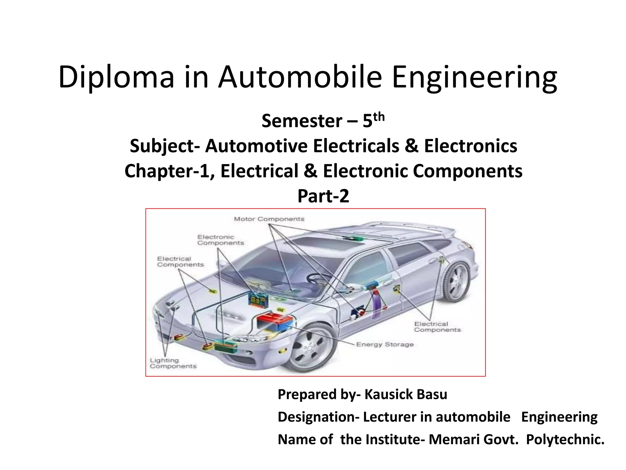
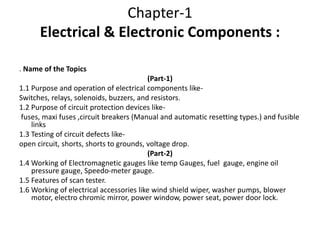
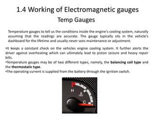
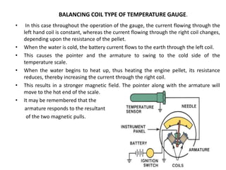
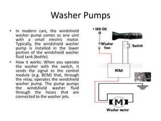
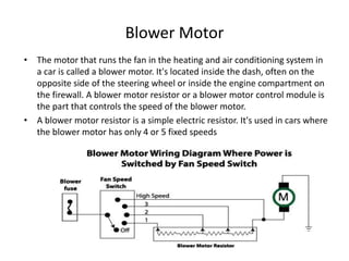
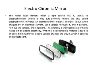
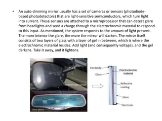
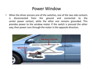
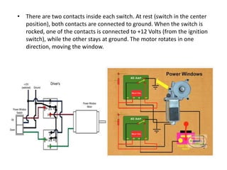
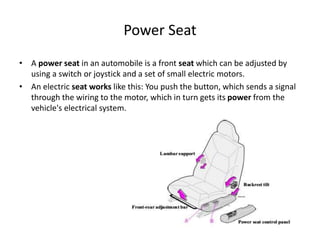
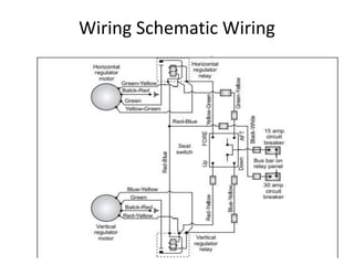
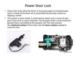
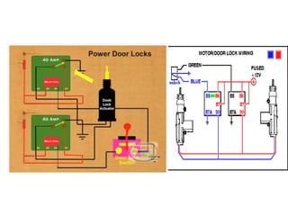
Diploma in Automobile Engineering
Prepared by- Kausick Basu
Designation- Lecturer in automobile Engineering
Name of the Institute- Memari Govt. Polytechnic.
Semester – 5th
Subject- Automotive Electricals & Electronics
Chapter-1, Electrical & Electronic Components
Part-2
Chapter-1
Electrical & Electronic Components :
. Name of the Topics
(Part-1)
1.1 Purpose and operation of electrical components like-
Switches, relays, solenoids, buzzers, and resistors.
1.2 Purpose of circuit protection devices like-
fuses, maxi fuses ,circuit breakers (Manual and automatic resetting types.) and fusible
links
1.3 Testing of circuit defects like-
open circuit, shorts, shorts to grounds, voltage drop.
(Part-2)
1.4 Working of Electromagnetic gauges like temp Gauges, fuel gauge, engine oil
pressure gauge, Speedo-meter gauge.
1.5 Features of scan tester.
1.6 Working of electrical accessories like wind shield wiper, washer pumps, blower
motor, electro chromic mirror, power window, power seat, power door lock.
1.4 Working of Electromagnetic gauges
Temp Gauges
Temperature gauges to tell us the conditions inside the engine's cooling system, naturally
assuming that the readings are accurate. The gauge typically sits in the vehicle’s
dashboard for the lifetime and usually never sees maintenance or adjustment.
•It keeps a constant check on the vehicles engine cooling system. It further alerts the
driver against overheating which can ultimately lead to piston seizure and heavy repair
bills.
•Temperature gauges may be of two different types, namely, the balancing coil type and
the thermostatic type.
•The operating current is supplied from the battery through the ignition switch.
• In this case throughout the operation of the gauge, the current flowing through the
left hand coil is constant, whereas the current flowing through the right coil changes,
depending upon the resistance of the pellet.
• When the water is cold, the battery current flows to the earth through the left coil.
• This causes the pointer and the armature to swing to the cold side of the
temperature scale.
• When the water begins to heat up, thus heating the engine pellet, its resistance
reduces, thereby increasing the current through the right coil.
• This results in a stronger magnetic field. The pointer along with the armature will
move to the hot end of the scale.
• It may be remembered that the
armature responds to the resultant
of the two magnetic pulls.
BALANCING COIL TYPE OF TEMPERATURE GAUGE.
Fuel Gauge
• A fuel gauge is an instrument used to indicate the level of fuel
contained in a tank. As used in vehicles, the gauge consists of two
parts: The sensing unit and the indicator.
BALANCING COIL TYPE OF FUEL GAUGE.
• It has two units a dash unit and a tank unit connected in series.
• When the ignition switch is turned ON the current from the battery flows through
both the units.
• The tank unit consists of a float mounted at one end of the hinged arm and a
sliding contact at the other end.
• The sliding contact moves along the resistance.
• The float lever moves up or down when the changes in the fuel level take place.
• When the fuel level in the tank begins to empty the sliding contact moves to the
left.
• Thus more current flows through the left hand coil of the dash unit, and a little of
it flows through the right hand coil.
• This results in the left hand coil being magnetically stronger than the right hand
one.
• The armature along with the pointer is moved towards the left side, thus
indicating a low fuel level in the tank.
• On the other hand, when the fuel level in the tank is high, the float moves up the
making the sliding contact to insert most of the resistance into the circuit.
• Now most of the current that flows through the left-hand coil also flows through
the right-hand coil.
• The right hand coil is relatively stronger and this causes the armature and pointer
to swing to the right, thereby indicating a high fuel level in the tank.
Engine oil pressure gauge
• The oil pressure gauge is one of the most important instruments in a car. It acts as
an indicator of the engine's overall well-being and as an early-warning system,
giving advance notice of any problems; a cause can be investigated before an
expensive breakdown occurs.
• This device reads the pressure of a vehicles engine lubrication system and serves
as a warning device to the driver against any likely damage to engine parts due to
insufficient lubricating oil.
• The oil pressure gauge can be of the Bourdon type, balancing coil type, or the
thermostatic type.
• BALANCING COIL TYPE
• It consists of two units namely the dash unit and the engine unit.
• A variable resistance is placed in the engine unit. An increase in the oil pressure
causes the diaphragm to get pushed outwards.
• This results in increase in the resistance at the engine unit, thus making the right-
hand coil of the dash unit relatively magnetically stronger than the left-hand coil.
• Consequently, the armature and the pointer swing towards the right to indicate a
higher oil pressure.
Speedo-meter gauge
• The job of the speedometer is to indicate the speed of a car in miles per
hour, kilometres per hour or both. Even in late-model cars, it is an analog
device that uses a needle to point to a specific speed, which the driver
reads as a number printed on a dial.
• Inside the speedometer, the cable turns a shaft with a small magnet on it.
The rotating magnetic field produces a varying pull on the metal ring
surrounding the magnet.
• • A pointer attaches to the metal ring. As the magnetic field spins, it causes
the ring to overcome a light spring and swing with the magnetic field. This
moves the pointer which then indicates the speed of the vehicle.
Electrical Speedometer
• There are two types of speedometers namely Mechanical type and Electrical type.
• The electrical speedometer operates on the principle that when an electrical
generator is driven off the gear box output shaft it generates a voltage which is
practically proportional to the speed.
• Fig shows a schematic circuit diagram of an electrical speedometer.
• Small permanent magnets are embedded in a brass wheel which is rotated by a
shaft at the gear box output shaft speed.
• A pick –up coil is placed near it. The voltage is induced in the coil when the
magnet passes it.
• These small voltage pulses are amplified by transistorized circuits and transformed
in to a direct current voltage exactly proportional to the number of impulses per
second received from the coil.
• Thus the speedometer indicates the vehicle speed.
1.5 Features of scan tester
• Scan testers display data and diagnostic trouble codes (DTCs) on computer systems and perform
many other diagnostic functions.
• On many vehicles, scan testers have the capability to diagnose various computer systems such as
engine, transmission, antilock brake system (ABS), suspension, and air bag.
• Scan testers vary depending on the manufacturer, but many scan testers have the following
features:-
• 1. Display Window: - It displays data and messages to the technician. Most scan testers display at
• least four readings on the display at the same time.
• 2. Memory Cartridge: - It plugs into the scan tester. These memory cartridges are designed for
specific vehicles and electronic systems.
• 3. Power Cord: - Connected from the scan tester to the battery terminals or cigarette lighter
socket.
• 4. Adapter Cord: - Plugs into the scan tester and connects to the data link connector (DLC) on the
vehicle.
• 5. Serial Interface: - Optional devices, such as printer, terminal, or personal computer, may be
connected to this terminal.
• 6. Keypad: - Allows the technician to enter data and reply to tester messages.
1.6 Working of electrical accessories like-
• The wiper switch sends the signal to
the control module. The control
module operates the wiper relay. The
relay sends 12-volt power to the
wiper motor. The motor rotates a little
arm that through links moves the
wiper arms.
• The wiper switch on the steering
column (multifunction switch)
commands the control module and
the control module operates the
wiper motor through wiper motor
relays.
• There could be up to 3 relays: one for
the wiper motor high speed circuit,
one the for low-speed circuit and one
for the intermittent wipers circuit.
Wind Shield Wiper
Washer Pumps
• In modern cars, the windshield
washer pump comes as one unit
with a small electric motor.
Typically, the windshield washer
pump is installed in the lower
portion of the windshield washer
fluid tank (bottle).
• How it works: When you operate
the washer with the switch, it
sends the signal to the control
module (e.g. BCM) that, through
the relay, operates the windshield
washer pump. The pump pumps
the windshield washer fluid
through the hoses that are
connected to the washer jets.
Blower Motor
• The motor that runs the fan in the heating and air conditioning system in
a car is called a blower motor. It's located inside the dash, often on the
opposite side of the steering wheel or inside the engine compartment on
the firewall. A blower motor resistor or a blower motor control module is
the part that controls the speed of the blower motor.
• A blower motor resistor is a simple electric resistor. It's used in cars where
the blower motor has only 4 or 5 fixed speeds
Electro Chromic Mirror
• The mirror itself darkens when a light source hits it, thanks to
electrochromism (which is why auto-dimming mirrors are also called
electrochromic mirrors). An electrochromic material changes colour when
charged by an electrical current. Send voltage through it, and it darkens.
Remove the voltage, and it lightens. This is largely a chemical reaction that is
kicked off by adding electricity. With the electrochromic material added to
an auto-dimming mirror, electric voltage changes the way in which it absorbs
and reflects light.
• An auto-dimming mirror usually has a set of cameras or sensors (photodiode-
based photodetectors) that are light-sensitive semiconductors, which turn light
into current. These sensors are attached to a microprocessor that can detect glare
from headlights and send a charge through the electrochromic material to respond
to this input. As mentioned, the system responds to the amount of light present.
The more intense the glare, the more the mirror will darken. The mirror itself
consists of two layers of glass with a layer of gel in between, which is where the
electrochromic material resides. Add light (and consequently voltage), and the gel
darkens. Take it away, and it lightens.
Power Window
• When the driver presses one of the switches, one of the two side contacts
is disconnected from the ground and connected to the
center power contact, while the other one remains grounded. This
provides power to the window motor. If the switch is pressed the other
way, then power runs through the motor in the opposite direction.
• There are two contacts inside each switch. At rest (switch in the center
position), both contacts are connected to ground. When the switch is
rocked, one of the contacts is connected to +12 Volts (from the ignition
switch), while the other stays at ground. The motor rotates in one
direction, moving the window.
Power Seat
• A power seat in an automobile is a front seat which can be adjusted by
using a switch or joystick and a set of small electric motors.
• An electric seat works like this: You push the button, which sends a signal
through the wiring to the motor, which in turn gets its power from the
vehicle's electrical system.
Wiring Schematic Wiring
Power Door Lock
• Power door locks allow the driver or front passenger to simultaneously
lock or unlock all the doors of an automobile by pressing a button or
flipping a switch.
• This system is quite simple. A small electric motor turns a series of spur
gears that serve as a gear reduction. The last gear drives a rack-and-pinion
gearset that is connected to the actuator rod. The rack converts
the rotational motion of the motor into the linear motion needed to
move the lock.
Practice Questions
1. Explain operation of various types of switches with neat sketch.
2. Explain operation of fuel gauge.
3. Explain with labelled diagram operation of power seat.
4. Draw simplified wiring diagram for blower motor and washer pump.
Label it.
5. Explain short to ground circuit test.
6. Explain operation of circuit breaker and fusible link.
7. Explain Relays, Solenoids, Buzzers, resistors.
8. Explain operation of speedometer gauge.
9. What is the use of engine oil pressure gauge? Explain.
10. Explain open circuit test to check circuit defects.
Bibliography
•Automotive Electrical Equipment by P.L. Kohli
•Text books of automobile engineering by Dr.kirpal Singh, Dr R.B. Gupta & S.K. Gupta.
•Text Book of Automotive Electrical And Electronics Systems. By P.D. Kulkarni
•www.google.com
Automotive Electricals & Electronics_Chapter 1_Part 2_5th Sem.pptx

Automotive Electricals & Electronics_Chapter 1_Part 2_5th Sem.pptx

  • 1.
    Diploma in AutomobileEngineering Prepared by- Kausick Basu Designation- Lecturer in automobile Engineering Name of the Institute- Memari Govt. Polytechnic. Semester – 5th Subject- Automotive Electricals & Electronics Chapter-1, Electrical & Electronic Components Part-2
  • 2.
    Chapter-1 Electrical & ElectronicComponents : . Name of the Topics (Part-1) 1.1 Purpose and operation of electrical components like- Switches, relays, solenoids, buzzers, and resistors. 1.2 Purpose of circuit protection devices like- fuses, maxi fuses ,circuit breakers (Manual and automatic resetting types.) and fusible links 1.3 Testing of circuit defects like- open circuit, shorts, shorts to grounds, voltage drop. (Part-2) 1.4 Working of Electromagnetic gauges like temp Gauges, fuel gauge, engine oil pressure gauge, Speedo-meter gauge. 1.5 Features of scan tester. 1.6 Working of electrical accessories like wind shield wiper, washer pumps, blower motor, electro chromic mirror, power window, power seat, power door lock.
  • 3.
    1.4 Working ofElectromagnetic gauges Temp Gauges Temperature gauges to tell us the conditions inside the engine's cooling system, naturally assuming that the readings are accurate. The gauge typically sits in the vehicle’s dashboard for the lifetime and usually never sees maintenance or adjustment. •It keeps a constant check on the vehicles engine cooling system. It further alerts the driver against overheating which can ultimately lead to piston seizure and heavy repair bills. •Temperature gauges may be of two different types, namely, the balancing coil type and the thermostatic type. •The operating current is supplied from the battery through the ignition switch.
  • 4.
    • In thiscase throughout the operation of the gauge, the current flowing through the left hand coil is constant, whereas the current flowing through the right coil changes, depending upon the resistance of the pellet. • When the water is cold, the battery current flows to the earth through the left coil. • This causes the pointer and the armature to swing to the cold side of the temperature scale. • When the water begins to heat up, thus heating the engine pellet, its resistance reduces, thereby increasing the current through the right coil. • This results in a stronger magnetic field. The pointer along with the armature will move to the hot end of the scale. • It may be remembered that the armature responds to the resultant of the two magnetic pulls. BALANCING COIL TYPE OF TEMPERATURE GAUGE.
  • 5.
    Fuel Gauge • Afuel gauge is an instrument used to indicate the level of fuel contained in a tank. As used in vehicles, the gauge consists of two parts: The sensing unit and the indicator. BALANCING COIL TYPE OF FUEL GAUGE.
  • 6.
    • It hastwo units a dash unit and a tank unit connected in series. • When the ignition switch is turned ON the current from the battery flows through both the units. • The tank unit consists of a float mounted at one end of the hinged arm and a sliding contact at the other end. • The sliding contact moves along the resistance. • The float lever moves up or down when the changes in the fuel level take place. • When the fuel level in the tank begins to empty the sliding contact moves to the left. • Thus more current flows through the left hand coil of the dash unit, and a little of it flows through the right hand coil. • This results in the left hand coil being magnetically stronger than the right hand one. • The armature along with the pointer is moved towards the left side, thus indicating a low fuel level in the tank. • On the other hand, when the fuel level in the tank is high, the float moves up the making the sliding contact to insert most of the resistance into the circuit. • Now most of the current that flows through the left-hand coil also flows through the right-hand coil. • The right hand coil is relatively stronger and this causes the armature and pointer to swing to the right, thereby indicating a high fuel level in the tank.
  • 7.
    Engine oil pressuregauge • The oil pressure gauge is one of the most important instruments in a car. It acts as an indicator of the engine's overall well-being and as an early-warning system, giving advance notice of any problems; a cause can be investigated before an expensive breakdown occurs. • This device reads the pressure of a vehicles engine lubrication system and serves as a warning device to the driver against any likely damage to engine parts due to insufficient lubricating oil. • The oil pressure gauge can be of the Bourdon type, balancing coil type, or the thermostatic type.
  • 8.
    • BALANCING COILTYPE • It consists of two units namely the dash unit and the engine unit. • A variable resistance is placed in the engine unit. An increase in the oil pressure causes the diaphragm to get pushed outwards. • This results in increase in the resistance at the engine unit, thus making the right- hand coil of the dash unit relatively magnetically stronger than the left-hand coil. • Consequently, the armature and the pointer swing towards the right to indicate a higher oil pressure.
  • 9.
    Speedo-meter gauge • Thejob of the speedometer is to indicate the speed of a car in miles per hour, kilometres per hour or both. Even in late-model cars, it is an analog device that uses a needle to point to a specific speed, which the driver reads as a number printed on a dial.
  • 10.
    • Inside thespeedometer, the cable turns a shaft with a small magnet on it. The rotating magnetic field produces a varying pull on the metal ring surrounding the magnet. • • A pointer attaches to the metal ring. As the magnetic field spins, it causes the ring to overcome a light spring and swing with the magnetic field. This moves the pointer which then indicates the speed of the vehicle.
  • 11.
    Electrical Speedometer • Thereare two types of speedometers namely Mechanical type and Electrical type. • The electrical speedometer operates on the principle that when an electrical generator is driven off the gear box output shaft it generates a voltage which is practically proportional to the speed. • Fig shows a schematic circuit diagram of an electrical speedometer. • Small permanent magnets are embedded in a brass wheel which is rotated by a shaft at the gear box output shaft speed. • A pick –up coil is placed near it. The voltage is induced in the coil when the magnet passes it. • These small voltage pulses are amplified by transistorized circuits and transformed in to a direct current voltage exactly proportional to the number of impulses per second received from the coil. • Thus the speedometer indicates the vehicle speed.
  • 12.
    1.5 Features ofscan tester • Scan testers display data and diagnostic trouble codes (DTCs) on computer systems and perform many other diagnostic functions. • On many vehicles, scan testers have the capability to diagnose various computer systems such as engine, transmission, antilock brake system (ABS), suspension, and air bag. • Scan testers vary depending on the manufacturer, but many scan testers have the following features:- • 1. Display Window: - It displays data and messages to the technician. Most scan testers display at • least four readings on the display at the same time. • 2. Memory Cartridge: - It plugs into the scan tester. These memory cartridges are designed for specific vehicles and electronic systems. • 3. Power Cord: - Connected from the scan tester to the battery terminals or cigarette lighter socket. • 4. Adapter Cord: - Plugs into the scan tester and connects to the data link connector (DLC) on the vehicle. • 5. Serial Interface: - Optional devices, such as printer, terminal, or personal computer, may be connected to this terminal. • 6. Keypad: - Allows the technician to enter data and reply to tester messages.
  • 13.
    1.6 Working ofelectrical accessories like- • The wiper switch sends the signal to the control module. The control module operates the wiper relay. The relay sends 12-volt power to the wiper motor. The motor rotates a little arm that through links moves the wiper arms. • The wiper switch on the steering column (multifunction switch) commands the control module and the control module operates the wiper motor through wiper motor relays. • There could be up to 3 relays: one for the wiper motor high speed circuit, one the for low-speed circuit and one for the intermittent wipers circuit. Wind Shield Wiper
  • 14.
    Washer Pumps • Inmodern cars, the windshield washer pump comes as one unit with a small electric motor. Typically, the windshield washer pump is installed in the lower portion of the windshield washer fluid tank (bottle). • How it works: When you operate the washer with the switch, it sends the signal to the control module (e.g. BCM) that, through the relay, operates the windshield washer pump. The pump pumps the windshield washer fluid through the hoses that are connected to the washer jets.
  • 15.
    Blower Motor • Themotor that runs the fan in the heating and air conditioning system in a car is called a blower motor. It's located inside the dash, often on the opposite side of the steering wheel or inside the engine compartment on the firewall. A blower motor resistor or a blower motor control module is the part that controls the speed of the blower motor. • A blower motor resistor is a simple electric resistor. It's used in cars where the blower motor has only 4 or 5 fixed speeds
  • 16.
    Electro Chromic Mirror •The mirror itself darkens when a light source hits it, thanks to electrochromism (which is why auto-dimming mirrors are also called electrochromic mirrors). An electrochromic material changes colour when charged by an electrical current. Send voltage through it, and it darkens. Remove the voltage, and it lightens. This is largely a chemical reaction that is kicked off by adding electricity. With the electrochromic material added to an auto-dimming mirror, electric voltage changes the way in which it absorbs and reflects light.
  • 17.
    • An auto-dimmingmirror usually has a set of cameras or sensors (photodiode- based photodetectors) that are light-sensitive semiconductors, which turn light into current. These sensors are attached to a microprocessor that can detect glare from headlights and send a charge through the electrochromic material to respond to this input. As mentioned, the system responds to the amount of light present. The more intense the glare, the more the mirror will darken. The mirror itself consists of two layers of glass with a layer of gel in between, which is where the electrochromic material resides. Add light (and consequently voltage), and the gel darkens. Take it away, and it lightens.
  • 18.
    Power Window • Whenthe driver presses one of the switches, one of the two side contacts is disconnected from the ground and connected to the center power contact, while the other one remains grounded. This provides power to the window motor. If the switch is pressed the other way, then power runs through the motor in the opposite direction.
  • 19.
    • There aretwo contacts inside each switch. At rest (switch in the center position), both contacts are connected to ground. When the switch is rocked, one of the contacts is connected to +12 Volts (from the ignition switch), while the other stays at ground. The motor rotates in one direction, moving the window.
  • 20.
    Power Seat • Apower seat in an automobile is a front seat which can be adjusted by using a switch or joystick and a set of small electric motors. • An electric seat works like this: You push the button, which sends a signal through the wiring to the motor, which in turn gets its power from the vehicle's electrical system.
  • 21.
  • 22.
    Power Door Lock •Power door locks allow the driver or front passenger to simultaneously lock or unlock all the doors of an automobile by pressing a button or flipping a switch. • This system is quite simple. A small electric motor turns a series of spur gears that serve as a gear reduction. The last gear drives a rack-and-pinion gearset that is connected to the actuator rod. The rack converts the rotational motion of the motor into the linear motion needed to move the lock.
  • 24.
    Practice Questions 1. Explainoperation of various types of switches with neat sketch. 2. Explain operation of fuel gauge. 3. Explain with labelled diagram operation of power seat. 4. Draw simplified wiring diagram for blower motor and washer pump. Label it. 5. Explain short to ground circuit test. 6. Explain operation of circuit breaker and fusible link. 7. Explain Relays, Solenoids, Buzzers, resistors. 8. Explain operation of speedometer gauge. 9. What is the use of engine oil pressure gauge? Explain. 10. Explain open circuit test to check circuit defects.
  • 25.
    Bibliography •Automotive Electrical Equipmentby P.L. Kohli •Text books of automobile engineering by Dr.kirpal Singh, Dr R.B. Gupta & S.K. Gupta. •Text Book of Automotive Electrical And Electronics Systems. By P.D. Kulkarni •www.google.com