Downloaded 101 times
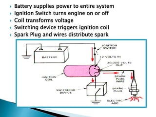
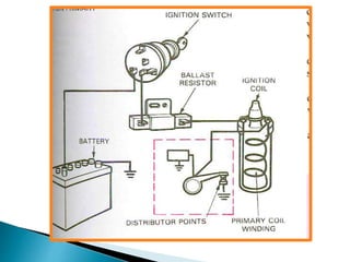
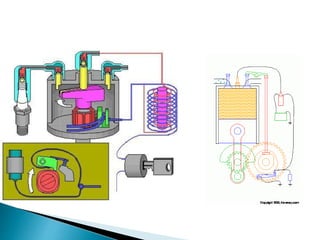
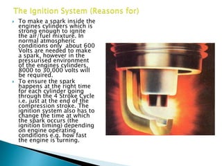
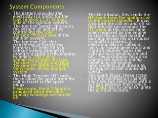
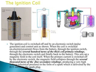
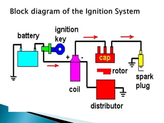
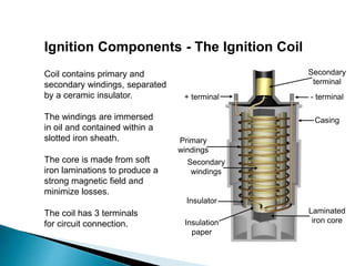
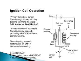
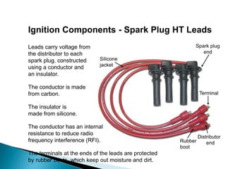
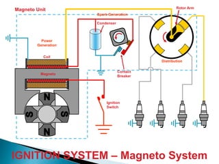
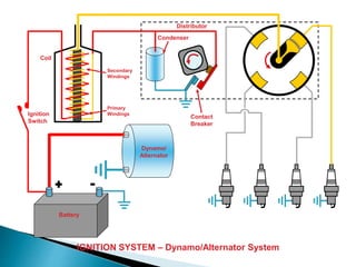
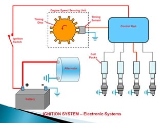
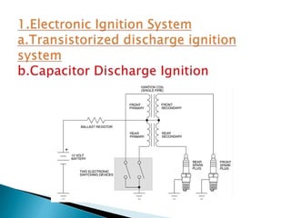
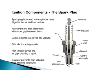

The document discusses various components and systems of an engine's ignition system. It describes the purpose of each component as well as how they work together. The key components include the ignition coil, distributor, spark plugs, and wires. The ignition coil transforms low voltage from the battery into high voltage required for sparking. The distributor times the spark and directs it to the correct spark plug. Modern systems use sensors and electronic control units to adjust ignition timing based on factors like engine speed and load. The goal is to ignite the fuel-air mixture at the optimal time for combustion.