Strength Improvement of Bus Body Structure with Design Modification
•
0 likes•97 views

https://www.irjet.net/archives/V10/i4/IRJET-V10I4127.pdf

Recommended
Recommended
More Related Content
Similar to Strength Improvement of Bus Body Structure with Design Modification
Similar to Strength Improvement of Bus Body Structure with Design Modification (20)
More from IRJET Journal
More from IRJET Journal (20)
Recently uploaded
Recently uploaded (20)
Strength Improvement of Bus Body Structure with Design Modification
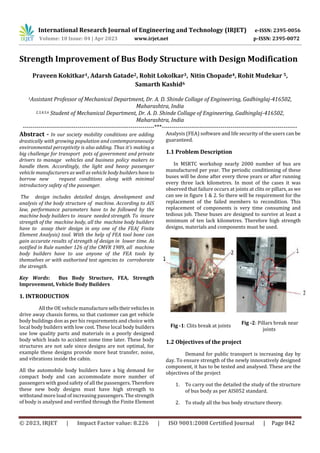
- 1. International Research Journal of Engineering and Technology (IRJET) e-ISSN: 2395-0056 Volume: 10 Issue: 04 | Apr 2023 www.irjet.net p-ISSN: 2395-0072 © 2023, IRJET | Impact Factor value: 8.226 | ISO 9001:2008 Certified Journal | Page 842 Strength Improvement of Bus Body Structure with Design Modification Praveen Kokitkar1, Adarsh Gatade2, Rohit Lokolkar3, Nitin Chopade4, Rohit Mudekar 5, Samarth Kashid6 1Assistant Professor of Mechanical Department, Dr. A. D. Shinde Collage of Engineering, Gadhinglaj-416502, Maharashtra, India 2,3,4,5,6 Student of Mechanical Department, Dr. A. D. Shinde Collage of Engineering, Gadhinglaj-416502, Maharashtra, India -------------------------------------------------------------------***--------------------------------------------------------------------- Abstract - In our society mobility conditions are adding drastically with growing population and contemporaneously environmental perceptivity is also adding. Thus it's making a big challenge for transport pots of government and private drivers to manage vehicles and business policy makers to handle them. Accordingly, the light and heavy passenger vehicle manufacturers as well as vehicle body builders haveto borrow new request conditions along with minimal introductory safety of the passenger. The design includes detailed design, development and analysis of the body structure of machine. According to AIS law, performance parameters have to be followed by the machine body builders to insure needed strength. To insure strength of the machine body, all the machine body builders have to assay their design in any one of the FEA( Finite Element Analysis) tool. With the help of FEA tool bone can gain accurate results of strength of design in lower time. As notified in Rule number 126 of the CMVR 1989, all machine body builders have to use anyone of the FEA tools by themselves or with authorised test agencies to corroborate the strength. Key Words: Bus Body Structure, FEA, Strength Improvement, Vehicle Body Builders 1. INTRODUCTION All the OE vehicle manufacturesellstheirvehiclesin drive away chassis forms, so that customer can get vehicle body buildings don as per his requirements and choice with local body builders with low cost. These local body builders use low quality parts and materials in a poorly designed body which leads to accident some time later. These body structures are not safe since designs are not optimal, for example these designs provide more heat transfer, noise, and vibrations inside the cabin. All the automobile body builders have a big demand for compact body and can accommodate more number of passengers with good safety of all the passengers. Therefore these new body designs must have high strength to withstand more load of increasing passengers. The strength of body is analysed and verified through the Finite Element Analysis (FEA) software and life security of the users can be guaranteed. 1.1 Problem Description In MSRTC workshop nearly 2000 number of bus are manufactured per year. The periodic conditioning of these buses will be done after every three years or after running every three lack kilometres. In most of the cases it was observed that failure occurs at joints at clits or pillars, as we can see in figure 1 & 2. So there will be requirement for the replacement of the failed members to recondition. This replacement of components is very time consuming and tedious job. These buses are designed to survive at least a minimum of ten lack kilometres. Therefore high strength designs, materials and components must be used. Fig -1: Clits break at joints 1.2 Objectives of the project Demand for public transport is increasing day by day. To ensure strength of the newly innovatively designed component, it has to be tested and analysed. These are the objectives of the project 1. To carry out the detailed the study of the structure of bus body as per AIS052 standard. 2. To study all the bus body structure theory. Fig -2: Pillars break near joints
- 2. International Research Journal of Engineering and Technology (IRJET) e-ISSN: 2395-0056 Volume: 10 Issue: 04 | Apr 2023 www.irjet.net p-ISSN: 2395-0072 © 2023, IRJET | Impact Factor value: 8.226 | ISO 9001:2008 Certified Journal | Page 843 3. Failure modes are studied and cause-effectdiagram is prepared. 4. To prepare Cause-effect diagram. To do thestudyof failure modes by components structural analysis and to find critical region for failure using suitable analysis software. 5. To provide solution to avoid failure of structure of bus. 6. To carry out analysis of modified structure using analysis software. 7. To validate the simulation results of modified structure of bus body by comparing theresultswith simulation results of existing structure of bus body. 2. Dimensional specifications for a bus body Specifications used in MSRTC- 2x2 parivartan bus are as follows. Below figure shows the dimensions used in MSRTC- 2x2 parivartan bus with the standards given in AIS_052 Table -1: MSRTC- 2x2 Parivartan dimension specification 3. Layout of Framework of a bus body Layout of a bus body is shown in the below figure with dimensions. Material used for body is aluminium. The framework is done by using M8 bolts with riveted joints. Fig shows the assembly of bus body according to dimensions. Fig.3 Left side view of the bus body frame Fig.4 Right side view of the bus body frame Fig. 5 Top (roof) frame view of bus body 4. Finite Element Analysis 4.1 Static Analysis Boundary conditions are used to restrict the body with constraints and different types of loads. In this problem bottom structure is attached to the chassisofthevehiclethat is the long members of the bottom structures are connected. Therefore the long members of the bottom frame are constrained with all degrees of freedom. Alsotheloadof5Kg
- 3. International Research Journal of Engineering and Technology (IRJET) e-ISSN: 2395-0056 Volume: 10 Issue: 04 | Apr 2023 www.irjet.net p-ISSN: 2395-0072 © 2023, IRJET | Impact Factor value: 8.226 | ISO 9001:2008 Certified Journal | Page 844 in X direction, 5Kg in Y direction and 10Kg in Z direction is applied. The loads applied can be seen in figure Therefore the forces acting are X direction = 5 x 9810 =49050 N Y direction = 5 x 9810 = 49050 N Z direction = 10 x 9810 = 98100 N Fig. 6 Applying boundary conditions 4.1.1 Static Analysis Result Fig. 7 Stress distribution Fig. 8 Failure part Stresses acting on the body structure can be seen in counter plot. The result shows the stress distribution in the body structure which can be seen in figure 6.3. In the figure it can be also seen that the stress concentration is moreattheclits. This is the part which is prone to failure and whichcanfail at the earliest during accidents. It can be seen in figure 6.4 that this is the critical area which will fail on repeated loads and timely maintenance is required. Therefore this part of the structure needs to be modified and strengthened to improve the life of the body structure. 4.2 Dynamic Analysis Dynamic type of analysis is divided into different types, they are as follows 1. Modal 2. Frequency/response 3. Transient/response 4. Random/vibration 4.2.1 Modal Analysis This analysis is carried out to find the systems natural frequency. Table No. 2 Natural Frequency
- 4. International Research Journal of Engineering and Technology (IRJET) e-ISSN: 2395-0056 Volume: 10 Issue: 04 | Apr 2023 www.irjet.net p-ISSN: 2395-0072 © 2023, IRJET | Impact Factor value: 8.226 | ISO 9001:2008 Certified Journal | Page 845 Fig. 9 Mode at 6.110Hz (Lateral bending) Fig. 10 Mode at 7.684Hz (Lateral bending) Fig. 11 Mode at 11.08Hz (Roof bending) Fig. 12 Mode at 12.73Hz (Twisting) Fig. 13 Mode at 15.41Hz (Shearing) Fig. 14 Mode at 18.06Hz (Roof bending) 4.2.2 Frequency/response type analysis The figures below show the result for frequency/response type of analysis. Figure 6.13 shows value of maximum/displacement of 3.117 m. Figure 6.14 shows the result for equivalent type of stress. It was observed that maximum stress was 63.244 MPa and the maximum/stress at clits was 49.447 MPa. Fig. 16 Displacement
- 5. International Research Journal of Engineering and Technology (IRJET) e-ISSN: 2395-0056 Volume: 10 Issue: 04 | Apr 2023 www.irjet.net p-ISSN: 2395-0072 © 2023, IRJET | Impact Factor value: 8.226 | ISO 9001:2008 Certified Journal | Page 846 Fig. 17 Stress distribution 5. Modification Required for Clit Due to the problem faced by the present design, the clit was required a new design to improve the strength. Therefore clit was redesigned with the dimensions 76.2 x 50.8 x 6 mm. Material selected is same as that of previous clit. Figure 7.2 shows the new design of the clit. Fig.18 Modified design of clit 5.1 Analysis results After redesigning the clit in the CAD software, the clit was replaced with the new model and again meshed and analysed for all the conditioned which was followed earlier. For frequency/responseanalysisitwasfoundthatmaximum displacement was 1.603m (figure 6.3) and maximum stress of 35.71 MPa (figure). Fig. 19 Maximum displacement Fig. 20 Stress distribution 6. Conclusion In the project the MSRTC bus body structure was designed and analysed because some parts were giving lot of maintenance issues. Thisproblem wassolvedbyredesigning the clit part of the bus body. Both old and new designs were analysed and compared. The below table number 8.1 shows the comparison of new and old design analysis. Table 8.1 Conclusion comparison ExistingStructure Modified Structure Displacement 3.117 1.603 Von-MisesStress 63.244 35.712 Stress in Clint 49.4 26.02 By seeing above table we can understand that with the modified design the structure of bus body can withstand more load and lasts longer. ACKNOWLEDGEMENT It gives us an immense pleasure to write an acknowledgement to this Paper, a contribution of all people who helped us realize it. We take this opportunitytoexpress our respectful regards to our beloved Principal Prof. K. S.
- 6. International Research Journal of Engineering and Technology (IRJET) e-ISSN: 2395-0056 Volume: 10 Issue: 04 | Apr 2023 www.irjet.net p-ISSN: 2395-0072 © 2023, IRJET | Impact Factor value: 8.226 | ISO 9001:2008 Certified Journal | Page 847 Joshi for motivate us to publish this paper. Also we express our deep sense of gratitude and appreciation to our beloved Project Guide Prof. Praveen Kokitakar for this enthusiastic inspiration and amicable in all phases of our Paper. REFERENCES A. Magnus G.H. Cruz, AlexandreViecelli, "A methodology for replacement of conventional steel by micro alloyed steel in bus tubular structures", Materials and Design29,Elsevier,pp.539-545,2008. B. J. Karliński, M. Ptak, P. Działak, E. Rusiński, "Strength analysis of bus superstructure according to Regulation No. 66 of UN/ECE", Archives of civil and Mechanical Engineering 14, Elsevier, pp.342– 353, 2014. C. A. Gauchía, E. Olmeda, M. J. L. Boada, B. L. Boada and V. Díaz, "Methodology for bus structure torsion stiffness and natural vibrationfrequencyprediction based on a dimensional analysis approach", International Journal of Automotive Technology, Vol. 15, No.3, pp. 451−461, 2014. D. G. Zhang, X. Zhang, and B. Liu, "The Study of Bus Superstructure Strength Based on Rollover Test Using Body Sections", AdvancesinMSECVol.2, AISC 129, Springer, pp.315–322, 2011. E. H. S. Kim, Y. S. Hwang, H. S. Yoon, "Dynamic Stress Analysis of a Bus Systems", Annual Hyundai Motor Company Conference, Korea, 2009. F. SachinThorat, G.Amba Prasad Rao, "Computational analysis of intercity bus Withimproved aesthetics and aerodynamic performanceonIndian roads", International Journal of Advanced Engineering Technology, E-ISSN, pp.0976- 3945,2011. G. S. Butdee, F. Vignat, "TRIZ method for light weight bus bodystructure design",Achievements in Material and Manufacturing Engineering, Vol 31, Issue 2, 2008. H. Prasannapriya. Chinta ,Dr.L.V.VenugopalRao, "A New Design and Analysis of Bus Body Structure", IOSR Journal of Mechanical and Civil Engineering, e- ISSN: 2278-1684,p-ISSN: 2320-334X, Volume 11, Issue 5 VolI,pp39-47, 2014. I. Automotive Industry Standard-052, “Code of Practice for Bus Body Design and Approval” IS 733- 1983 “Specification for wrought Aluminum and Aluminum alloy bars, rods and Sections” J. Nitin Gokhale, “Practical Finite Element Analysis”, 2007