Download to read offline


![International Research Journal of Engineering and Technology (IRJET) e-ISSN: 2395-0056
Volume: 06 Issue: 04 | Apr 2019 www.irjet.net p-ISSN: 2395-0072
© 2019, IRJET | Impact Factor value: 7.211 | ISO 9001:2008 Certified Journal | Page 2912
DISCUSSION
In this analysis we have studied the MILD STEEL properties
are greater than as compare to ALLOY STEEL. For making a
chassis of MILD STEEL is a suitable material for carry 40
Tonnes load.
8. CONCLUSONS
From above Study it is conclude that for chassis mild steel is
best material than alloy steel material aspertheAnsysresult
obtained. In order to examine the performance
characteristics of thechassis,Structural andthermal analysis
were conducted. The following conclusion was obtained.
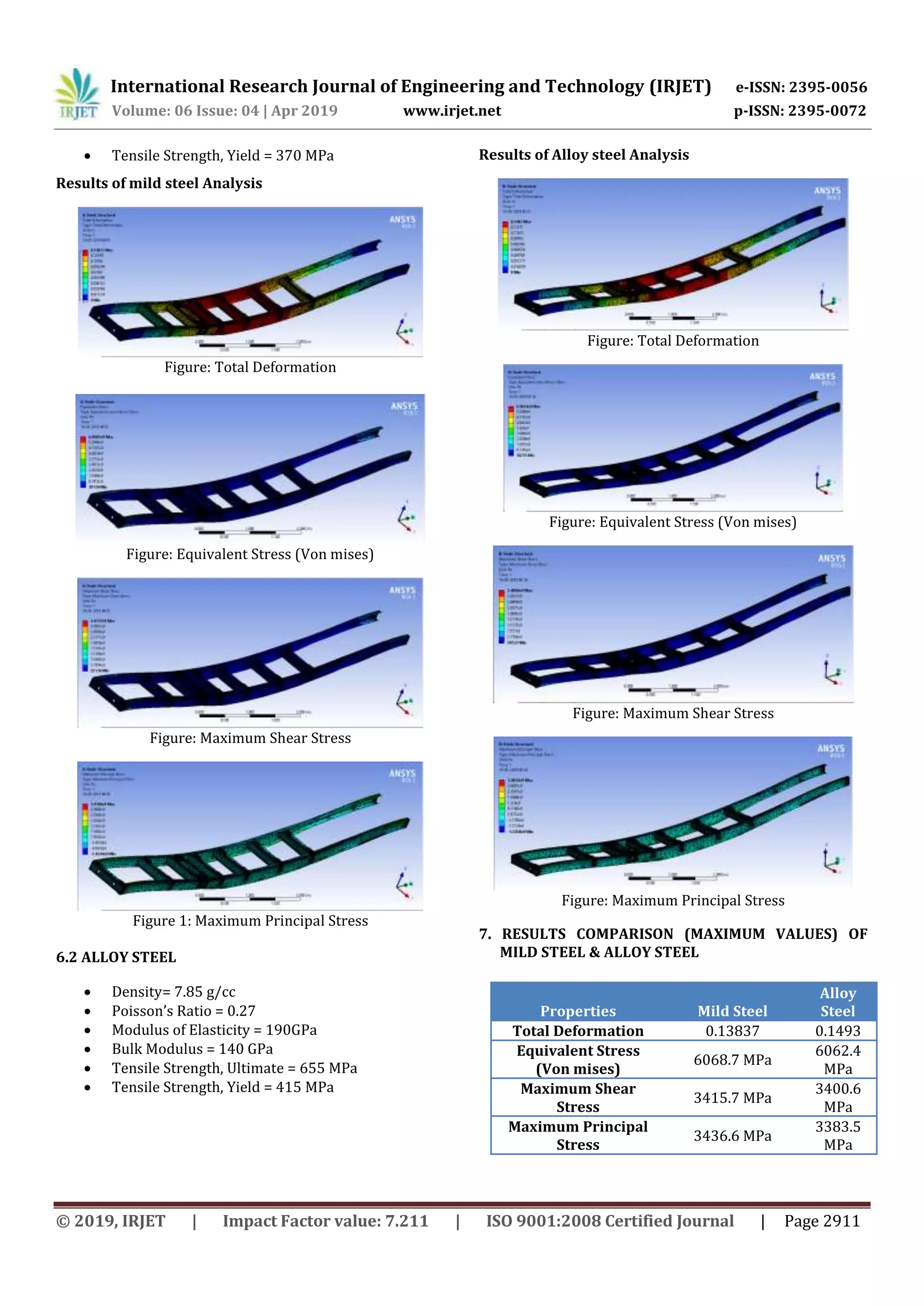
1. For chassis the maximum shear stress that produce for
mild steel material is 34157 Mpa which is greater than
the for Alloy steel i.e. 3400.6 Mpa. Also as per theweight
and cost comparison the mildsteel material ispreferred.
2. For chassis the Equivalent and produced is 6068.7 Mpa
for mild steel material which is greater than value
obtained by using Alloy steel material i.e. 6062.4 Mpa.
Also as per weight and cost comparison the Mild steel
Material is preferred
REFERENCES
[1] Tanveer Ahamed Bankapur,Lohitesh Jaga
Kumar,Dr.Irfan G,“Design and Analysis of Dual plate
Check Valve”,IJIET volume 07, Issue 01,June 2016,pp
422-426
[2] Design of machine elements II by Prof. J.B.K.DasandP.L.
Srinivasa Murthy, Sapna book house (P) Ltd., 2010
[3] Company, Houghton Mifflin Harcourt Publishing. "The
American Heritage Dictionary entry:
chassis". Www.ahdictionary.com.Retrieved 2017-05-21.
[4] "Chassis definition and meaning | Collins English
Dictionary". Www.collinsdictionary.com.Retrieved 2017-
05-21.
[5] Association of Licensed Automobile Manufacturers (U.S.)
(1922). Official Handbook of Automobiles. National
Automobile Association. p. 180. OCLC 6360726.
Retrieved 10 September2010.
BIOGRAPHIES
Ansari Mohd Abuzar Mohd Naeem
Student, Dept of mechanical engg,
Padm. Dr.V.B.Kolte college of
engineering Malkapur 443101
Ghulam Tausif Ghulam Younus
Student, Dept of mechanical engg,
Padm. Dr.V.B.Kolte college of
engineering Malkapur 443101
Mohd Ismail Zainulabedin
Student, Dept of mechanical engg,
Padm. Dr.V.B.Kolte college of
engineering Malkapur 443101
M Tausif M Sharif
Student, Dept of mechanical engg,
Padm. Dr.V.B.Kolte college of
engineering Malkapur 443101
Tanveer Baig Naseer Baig
Student, Dept of mechanical engg,
Padm. Dr.V.B.Kolte college of
engineering Malkapur 443101](https://image.slidesharecdn.com/irjet-v6i4619-190706095729/75/IRJET-Chassis-Design-Analysis-5-2048.jpg)

This document describes the design and analysis of a truck chassis. The chassis was modeled in CAD software including AutoCAD and CATIA. Finite element analysis was then performed on the chassis model in ANSYS to evaluate stresses and deflections. The objectives were to study chassis principles, investigate potential problems, create 3D models, and suggest design improvements through FEA. The chassis was meshed and simulated under static and dynamic loading conditions to determine high stress areas and optimize the chassis design.