SlideShare a Scribd company logo
1 of 10
Download to read offline
International Research Journal of Engineering and Technology (IRJET) e-ISSN: 2395-0056
Volume: 04 Issue: 08 | Aug -2017 www.irjet.net p-ISSN: 2395-0072
© 2017, IRJET | Impact Factor value: 5.181 | ISO 9001:2008 Certified Journal | Page 1829
SEISMIC ISOLATION BY INTRODUCING LARGE SIZED AGGREGATES
Suhas Jain C B1, Dr. B K Raghu Prasad2, Dr. Amarnath K3
1Student, M-Tech Structural Engineering, The Oxford College Of Engineering, Karnataka, India
2Professor, Dept. of Civil Engineering, IIS-c, Karnataka, India
3HOD & Professor, The Oxford College Of Engineering, Karnataka, India
----------------------------------------------------------***--------------------------------------------------------------
Abstract - The system comprising of the use of large
sized aggregates as isolating material is discussed in this
paper. The attempt is made to understand the mechanism of
the system which is pivoted on the phenomenon of stiffness
and collision between the accommodated aggregates in
system. It is a passive way of Seismic Isolation and exerted
seismic force is conveyed through the system via collision
between accommodated aggregates leading in dissipation of
seismic energy. The arrangementofsystemencouraginglesser
value of work done is more suitable for Isolation. The above
discussed work is done using Staad-pro v8i software
Key Words: Seismic Isolation, Time history analysis
1. INTRODUCTION
Seismic Isolation concept was first reported by John
Milne during 1890s and later on widely implemented as
seismic protection system in seismic prone areas. The term
Base refers to Foundation of the Structure and Isolation
refers to reducing the interaction between the Ground and
structure resting over it. Base Isolation is a Passive way to
reduce demand and it is simple design approach to reduce
the earthquake damage potential. Three major thingsa Base
Isolation system should accomplish are,
 Horizontal Flexibility
 Energy Dissipation
 Vertical Flexibility
1.1 Seismic Isolation Devices
 Laminated Rubber bearing ( Elastomeric bearing )
 Viscous Fluid Damper
 Lead Rubber Bearing
 Spherical Sliding Bearing ( Friction Pendulum )
Althoughtheinstallationoftheabovementioneddamping
devices reduce the seismic response in structures, they are
limited in practice due to their high cost. As a result
application of this system is restricted to projects where its
benefit exceeds cost requirement. This major drawback can
be fulfilled by replacing the above mentioned devices with
naturally available stone aggregates crushed to required
proportions. The Isolating system discussed here isassumed
to be well suited forRaft foundation.Initiallypenetrationtest
is conducted to make sure that the available earth after
excavation is hard enough to bear the aggregates against
penetration of the same in to the surrounding earth. It is
proceeded by dumping preconceived mass of stone
aggregates in excavated foundation pit. If scenario demands,
covering may be provided along the periphery of the mass to
prevent against penetration of mass in to surrounding earth.
The provided mass is compacted to a known density.
Subsequently raft is placed on the arrangement. The typical
layout of the raft coupled with aggregate Isolating system is
shown in the following figure.
Fig 1.1 RAFT COUPLED WITH LARGE SIZED
AGRREGATE
( The figure represents the position of aggregates in
discussing Isolating system )
As mentioned above, typical section across the raft
representing the position of stone aggregates without any
covering provided along the peripheryofthearrangementis
shown in above figure. In case of any existence of adverse
ground condition ( silty sand, moist earth ) is noticed near
foundation, Tar sheet as covering material may be provided
along the periphery of the stone aggregates to make the
Isolating system water proofing and also to held the stone
aggregates in position to withstand against dispersion of
aggregates in to surrounding Earth.
2. METHODOLOGY
The system comprises the use of large sized aggregatesas
isolating material. The mechanism of the system is pivoted
on the phenomenon of stiffness and collision between the
accommodated aggregates in system. It is a passive way of
International Research Journal of Engineering and Technology (IRJET) e-ISSN: 2395-0056
Volume: 04 Issue: 08 | Aug -2017 www.irjet.net p-ISSN: 2395-0072
© 2017, IRJET | Impact Factor value: 5.181 | ISO 9001:2008 Certified Journal | Page 1830
Seismic Isolation, Seismic force is conveyed through the
system via collision between accommodated aggregates.
Fig 1.2 Typical section of system
( Figure represents the typical section of Isolating
system where the stone aggregates are connected by
links/springs )
During the process, the gained collision intensity by
aggregates is directly proportional to dissipated seismic
energy unless the boundary conditions are considered. The
vital boundary conditions to be considered are,
 Density of surrounding earth (naturally of Lithosphere)
 Surface hardness and moisture content of bounding earth
 Weight of Structure
The layers of solid masses are modeled and the bottom
most layer of solid masses are assigned fixed restraint. All
solid masses are connected to each other by springs
assigning the stiffness values varying from zero for very
loose condition to infinity for very stiff/rigidcondition.Thus
the bottom layer is made fixed to groundandthesubsequent
upper layers are subjected to experience all 6 Degrees of
Freedom and its magnitude will vary with respecttovarying
stiffness of connecting springs and applied lateral force. The
stiffness values assigned are according to the compaction of
aggregates mass in actual practice. The analysis is done by
assigning uniform stiffness for springs. With reference to
compaction of whole mass of aggregate in actual, the exact
stiffness between any two solid masses is unpredictableand
thus the stiffness values of spring shall be randomly varied
for analysis purpose. The behavior of system is analyzed for
free vibration state and subsequently the structure is made
to rest on the system and responses are compared with
conventional structure.
It is known that largely arranged particles when hit each
other, they dissipates energy through heat. In fact loose and
non-uniformly packed particles are much more effective.
While packing certain sensitive electronic instruments,they
are surrounded by loosely and randomly arranged
thermocole particles filled with air,theidea beingthatunder
impact to the bag containing the instrument, the thermocole
particles collide each other smoothly as suspension is
provided in the form of air filling in them, leading to less
impact on instrument. This phenomenon is been carried
here by replacing individual thermocole units by stone
aggregates, air filling is replaced by soil mass and link
elements, impact on bag is here considered as adverse
seismic activity and finally instrument inside the bag is
replaced by the structure.
Fig 1.3 TYPICAL SECTION OF ISOLATING SYSTEM
MODELED IN STAAD-PRO
( Arrangement of aggregates in typical section
modeled in Staad-pro software is shown in the figure.
Here the soil mass is provided as link element between
stone aggregates )
As shown in the above figure the stone aggregates are
packed by providing soil mass and air gap in between them.
The modeling of isolating system is done in Staad pro V8i
software. Initially the material propertiesofstoneaggregate,
soil mass and link elements are defined. The provision is
provided in Staad pro software to model solid elementsand
thus each stone aggregate is modeled as solid element by
assigning their respectiveproperty.Theconnectionbetween
the stone aggregates is done in two ways i.e. by providing,
a) line element at corners of solid stone mass assigning
preconceived stiffness/Young’s Modulus value.
b) Solid element of soil mass at all edges of stone
aggregate.
The study is carried out by considering theTimeHistory
analysis data of El Centro Earthquake. The deformed shape
of typical section under the application of seismic force is
shown in the following figure,
Fig 1.4 BEHAVIOUR OF AGGREGATES
International Research Journal of Engineering and Technology (IRJET) e-ISSN: 2395-0056
Volume: 04 Issue: 08 | Aug -2017 www.irjet.net p-ISSN: 2395-0072
© 2017, IRJET | Impact Factor value: 5.181 | ISO 9001:2008 Certified Journal | Page 1831
The above mentioned typical section is made to
experience the seismic activity and as expected earlier we
noticed the deformed pattern of arrangement represents
significantly the existence of collision between the stone
aggregates. Analyzing the behavior of system, conclusion
can be drawn that propagation of seismic wavesthroughthe
arrangement occurs via collision between the
accommodated aggregates and leading to dissipation of
seismic energy. However impact being contact mechanics,is
not modeled in the present work. The springs representing
the resistance between the aggregates deform to absorb the
energy. The problem is considered as linear, if non-linearity
and hysteresis curve are considered, even the dissipated
energy can be obtained. Thus the Raft is suspended from
impact of adverse seismic waves. The soil mass provided
between stones offers suspension for inter-particlecollision
and in turn the whole arrangement ofIsolationsystemoffers
suspension against direct impact of adverse seismic waves
on structure.
The System is assumed to be well suited for Raft footing.
Initially penetration test is conducted to make sure that the
available Earth after excavation is hard enough to bear the
aggregates against penetration of the same in to earth. It is
proceeded by dumping calculated mass of aggregates in
excavated pit. If scenario demands , the covering may be
provided along the periphery of the mass to persist against
penetration of mass in to the surrounding earth. The
provided mass is compacted to preconceived density. All
sectional properties, physical properties must achieve
preconceived data. SubsequentlyRaftismadetosettleabove
the arrangement as shown in typical section.
3. MODELLING OF ISOLATING SYSTEM
The heart of the Isolating system is being the nature of
aggregates, each aggregate is modeled as solid element and
assigned with respective properties of naturally available
stone aggregate. Provision to model solid element and
assigning required properties to same is been provided in
Staad Pro software.
The system is assemblage of a largenumberofaggregates.
In order to analyze its behavior, initially modeling of single
unit composed of 2 stone masses fastened by links and soil
mass is done. Subsequently number of units areincreased to
achieve required size.
A typical model including two solid elements connected
to each other by line elements provided as link at all four
corners of solid is shown in the following Figure.
Fig 1.5: MODEL OF TWO STONE MASS
( Single unit of the Isolating system is shown in
figure which is composed of 2 stone masses connected
to each other by line elements to act as link of desired
stiffness )
As mentioned above, all modeling and analysis work is
done in Staad Pro V8i software. Modelingofstoneaggregate
of required size is done using Draw Solid command.Keeping
the size of aggregate as reference eight nodes are created
and is proceeded by drawing solid element using Add 8
Noded Solids command. Subsequently Line element of
preconceived thickness & stiffness properties is drawn
between the stone aggregates.
Fig 1.6: STAAD PRO- 2 SOLID MODEL
( Typical modeling of two solid masses in Staad-
Pro software is shown in above figure )
The project is carried out by considering 60mm size of
stone aggregate and 20mm diameter of circularlineelement
which is provided as link element as standard size. Stiffness
of link elements is varied from 0.001 to 10^7 KN/m. All
corners of adjacent solids are connected with link elements.
The stiffness values assigned for beam elements &
corresponding Young’s & Shear Modulus are as follows,
International Research Journal of Engineering and Technology (IRJET) e-ISSN: 2395-0056
Volume: 04 Issue: 08 | Aug -2017 www.irjet.net p-ISSN: 2395-0072
© 2017, IRJET | Impact Factor value: 5.181 | ISO 9001:2008 Certified Journal | Page 1832
Table -1: Properties of Line elements
STIFFNESS
(K KN/m)
YOUNG’s
MODULUS
(E
KN/m^2)
SHEAR
MODULUS
(G
KN/m^2)
0.01 0.32 0.1455
0.1 3.2 1.4545
1.0 32 14.5455
100 3200 1454.5455
10000 3.2x10^5 145454.54
55
25x10^5 8x10^7 3.6x10^7
50x10^5 2x10^8 9x10^7
1x10^7 3.2x10^8 1.45x10^8
Similarly, a typical model including two stoneaggregates
connected to each other by soil mass modeled as solid
element is provided as link member at edges of solid is
shown in the following Figure.
Fig 1.7: Two stones plugged with soil mass
( Single unit representing the Soil mass as connecting
element between two stones is shown in above figure )
As shown in above Figure, soil mass is sandwiched
between stone aggregates. The highlighted part in figure
represents soil mass. Young’s Modulus of soil mass is varied
from 15000 KN/m^2 for loose soil mass to 30000 KN/m^2
for fully compacted soil mass & is directly proportional to
stiffness between aggregates. The values of E and G of soil
mass are,
Table 1.2: Properties of Soil mass
Young’s
Modulus, E
(KN/m2)
Shear
Modulus, G
(KN/M2)
Stiffness,
K
(KN/m)
15000 ( loose ) 5358 2700
20000 ( medium ) 7145 3600
25000 ( stiff ) 8929 4500
30000 ( fully
compacted )
10715 5400
The solid massesmodeledalongtheperipheryofthesystem
are assigned with the properties of Earth crust. The material
properties of Stone, Crust, Sand, Horizantle and Vertical line
elements of a typical example model is shown in the Figure
below. By keeping the materialpropertyofstoneandCrustas
constant, the properties of sand and horizontal links are
varied by assigning the properties listed out in Table 1.3
Table 1.3: Material Properties
The properties of connecting elements listed out in Table
1.3 is kept as standard and number of models with different
sizes, cross sections, loadings were created and link
elements in each model is assigned with each material
property. Thus the behavior of each different model is
studied by assigning all stiffness properties mentioned in
Tables 1.3 above. The gap between the stones aggregates in
actual site varies, but for modeling purpose uniform gap of
thickness 20mm filled with soil mass is considered.
The different sizes of system are modeled for the analysis
purpose and is varied from 0.0005 m3 to 4 m3.
The following list of sizes of arrangement are
considered for analysis purpose,
1. ( 0.06 x 0.18 x 0.08 ) m
2. ( 0.14 x 0.18 x 0.08 ) m
3. ( 0.14 x 0.18 x 0.16 ) m
4. ( 0.06 x 1.00 x 0.50 ) m
5. ( 0.06 x 1.62 x 0.82 ) m
6. ( 1.00 x 1.00 x 0.25 ) m
7. ( 1.00 x 1.00 x 0.50 ) m
8. ( 1.40 x 1.40 x 0.25 ) m
9. ( 1.40 x 1.40 x 0.50 ) m
10. ( 4.00 x 4.00 x 0.25 ) m
International Research Journal of Engineering and Technology (IRJET) e-ISSN: 2395-0056
Volume: 04 Issue: 08 | Aug -2017 www.irjet.net p-ISSN: 2395-0072
© 2017, IRJET | Impact Factor value: 5.181 | ISO 9001:2008 Certified Journal | Page 1833
Fig 1.8 : Different sizes of system
( Figure shows the different sizes and arrangement
of stone masses, soil masses and line elements )
All the modeled sections are analyzed by applying
vertical load where the load denotes weight of structure in
actual. The application of vertical load is carried out by
placing Plate element of concrete material of suitable
sections satisfying desired load quantity above the
arrangement of aggregates. The Plate elementresembles the
raft footing in actual which made it to use as loadingelement
here & all models are assigned with constant seismic
parameters of El Centro Earthquake. The typical section of
loading on Isolating system and loads applied for analysis
purpose corresponding to cross section of plate element are
as follows,
Fig 1.9: Loading on system
( Plate element as loading material is placed above
the arrangement is shown here )
Table 1.4 (a) & (b) : Sizes of Plate element
corresponding to loading
PLATE DIMENSION
( L x B x D ) m
LOAD in KN
( 0 x 0 x 0 ) 0
( 0.94 x 0.94 x 0.05 ) 1.00
( 0.94 x 0.94 x 0.1 ) 2.00
( 0.94 x 0.94 x 0.2 ) 4.24
( 0.94 x 0.94 x 0.4 ) 8.50
( 0.94 x 0.94 x 1.6 ) 12.72
( 0.94 x 0.94 x 0.8 ) 17.00
( 0.94 x 0.94 x 1.0 ) 21.20
PLATE DIMENSION
( L x B x D ) m
LOAD in KN
( 0 x 0 x 0 ) 0
( 1.34 x 1.34 x 0.023 ) 1.00
( 1.34 x 1.34 x 0.046 ) 2.00
( 1.34 x 1.34 x 0.100 ) 4.30
( 1.34 x 1.34 x 0.197 ) 8.50
( 1.34 x 1.34 x 0.300 ) 13.00
( 1.34 x 1.34 x 0.394 ) 17.00
( 1.34 x 1.34 x 0.500 ) 21.55
The above mentioned loadings in Table (a) & (b) are done
for sections ( 1.00 x 1.00 x 0.25 )m, ( 1.00 x 1.00 x 0.50 )m, (
1.40 x 1.40 x 0.25 )m, ( 1.40 x 1.40 x 0.50 )m only.
The analysis is carried out for different compaction
values. Predominantly Compactionvalueisusedtofix/check
the depth of system. The compaction value of system can be
varied by two criteria, i.e. by keeping volume as constant,
1. Increasing stiffness/Young’s Modulus of connecting
element
The system is composed of large number of units containing
2 stone mass & an link each, values of stiffness & Young’s
modulus of links is directlyproportional tocompactionvalue
of system. The various values of stiffness & Young’smodulus
is shown in Table (1) & (2) are assigned and analysis is
carried out.
2. Increasing number of stone count by reducingthickness
of soil element.
Parallel way of varying compaction value of system is by
keeping volume as constant thickness of link element is
varied which in turn leads to number of stone count. Unit
density of stone mass is same, variation in its count with
constant system’s volume leads to variation in density of
system. Density of any system is directly proportional to
compaction value.
The bottom most layer of Stone aggregates
existing in contact with Ground below are assigned Fixed
restraint and the layers above are connected by providing
links. The typical arrangement is shown in following Figure,
International Research Journal of Engineering and Technology (IRJET) e-ISSN: 2395-0056
Volume: 04 Issue: 08 | Aug -2017 www.irjet.net p-ISSN: 2395-0072
© 2017, IRJET | Impact Factor value: 5.181 | ISO 9001:2008 Certified Journal | Page 1834
Fig 1.10 : Support restraint
( All the joints which are in direct contact with below
ground are assigned with fixed restraint )
The periphery stone aggregates along the direction of
seismic wave are assigned with load of El Centroearthquake
data. The earthquake load is assigned to highlighted solid
masses of the arrangement shown in below Figure,
Fig 1.11 : Application of Earthquake load
( The highlighted masses along the periphery are
assigned with earthquake load )
For Time-History analysis purpose El Centro earthquake
data is assigned for all models and comparison is done
assuming the system is free from other external
disturbances. The acceleration values of El Centro
Earthquake for a time period up to 2.24 seconds are
considered for analysis purpose.
Fig 1.12 : Acceleration-Time History Plot
( Ground motion data recorded at a site in El Centro,
California Imperial Valley earthquake of May 18, 1940
is shown in figure )
The number of modes are restricted to 10 in the study and
the first mode shape of a typical arrangement is shown
below. The analysis of all models with different size, cross
sections, loadings, stiffness ofconnecting membersiscarried
out by assigning the time period and corresponding
acceleration data of El Centro earthquake.
Initially the behavior of two stone aggregates linked with
sand mass and surrounded by crust element is drawn and
subsequently the number of all elements are increased and
relative responses are drawn. The example models and their
Natural Frequency, deflected shape along with size,
corresponding Stiffness/Young’s Modulus of connecting
element, Massparticipationfactors,Time-Accelerationcurve,
Base reaction and Work done are listed below. The
mentioned parameters are determined for all models
categorized under different stiffness, sizes, varying imposed
loads, but the most efficient models and their behavior are
listed out below. The case in which the value of work done is
less, that arrangement is highly encouraged for isolating
system.
Ex 1- Size = ( 0.06 x 0.18 x 0.08 ) m
Young’s Modulus (E) = 30000 kN/m2
Load = Selfweight
Fig 1.13 : Model & First Mode shape
Model of two stone masses of60mmsizeeachishighlighted
in figure connected to one other by soil mass of thickness
being 20mm is shown in figure. The material property of soil
mass assigned with very less stiffness value whose Young’s
modulus being 15000 kN/m2. All the supports are assigned
Fixed restraint. The analysis is done considering El-Centro
earthquake data the very firstmode shape of arrangement is
shown above.
Table 1.5 : Frequency, Period & corresponding
Mode numbers
International Research Journal of Engineering and Technology (IRJET) e-ISSN: 2395-0056
Volume: 04 Issue: 08 | Aug -2017 www.irjet.net p-ISSN: 2395-0072
© 2017, IRJET | Impact Factor value: 5.181 | ISO 9001:2008 Certified Journal | Page 1835
The vales of frequencies, periods for corresponding modes
are tabulated. The gradual decrease of time period and
increase in frequency is observed in the analysis.
Table 1.6 : Mass Participation Factors
The massparticipationvaluesanditscumulativeweight
of above model in all global directions is shown in above
Table. The arrangement is experiencing maximum
response/deformation in global X-direction.
Fig 1.14 : Model & Time v/s Displacement spectra
The spectra relating Time and acceleration values in all
three i.e. X, Y and Z direction is shown in above figure. The
arrangement is experiencing maximum acceleration at time
1.58 s. The acceleration is very much less in Z- direction.
Table 1.7 : Base Reaction
Under the action of ground motion on arrangement, the
stone masses in the top layer experiencing maximum
deformation is noticed. The base reaction and displacement
experienced by the top most stone mass is highlighted in
Table.
Table 1.8 : Work done
Work done = Base reaction x Lateral displacement
The model experiencing less values of work done is
more suitable and efficient arrangement. The work done
values in directions X, Y , Z and equilibrium state are
tabulated above.
Ex 2- Size - ( 1.40 x 1.40 x 0.25 ) m
Young’s Modulus (E) = 30000 kN/m2
Load = 21.55 kN
Fig 1.15 : Model & First Mode shape
Model of system of size being 0.50 m3 composed of
stone masses of 60mm size each connected to one other by
soil mass of thickness being 20mm is shown in figure. The
material property of soil mass assigned with high stiffness
value whose Young’s modulus being 30000 kN/m2. All the
supports are assigned Fixed restraint. The loading on
arrangement is done in the form of Plate element. The
analysis is done considering El-Centro earthquake data and
the very firstmode shape of arrangement is shown above.
International Research Journal of Engineering and Technology (IRJET) e-ISSN: 2395-0056
Volume: 04 Issue: 08 | Aug -2017 www.irjet.net p-ISSN: 2395-0072
© 2017, IRJET | Impact Factor value: 5.181 | ISO 9001:2008 Certified Journal | Page 1836
Table 1.9 : Frequency, Period & corresponding
Mode numbers
The values of frequencies, periods for corresponding
modes are tabulated. The gradual decrease of time period
and increase in frequency is observed in the analysis.
Table 1.10 : Mass Participation Factors
The massparticipationvaluesanditscumulativeweight
of above model in all global directions are shown in above
Table. The arrangement is experiencing maximum
response/deformation in global Z-direction.
Fig 1.16 : Model & Time v/s Displacement spectra
The spectra relating Time and acceleration values in X, Y
and Z directions is shown in abovefigure.Thearrangementis
experiencing maximum acceleration at time 1.58 s.
Table 1.10 : Base Reaction
Under the action of ground motion on arrangement, the
stone masses in top layer experiencing maximum
deformation is noticed. The base reaction and displacement
experienced by the top most stone mass is highlighted in
above Table.
Table 1.11 : Work done
Work done = Base reaction x Lateral displacement
The model experiencing less values of work done is more
suitable and efficient arrangement and the work donevalues
in directions X, Y , Z and equilibrium state are tabulated
above.
The response of system composed of stone masses
connected to one another through springs/line elements
greatly depends on assigned stiffness values for link
elements ranging from very loose/ zero stiffness to very
large stiffness value when the aggregatesareinrigidcontact.
However the arrangement in which the work done value
is less, is more encouraged, here the arrangement of
isolation system consisting soil mass of Young’s modulus
30000 kN/m2 is adopted for furtherwork whichincludes the
comparison between conventional fixed base structure and
structure plugged with isolation system.
The typical twenty storied single bay framed
structure is considered for the comparision purpose whose
plan dimensions being (3x3) m and height of complete
structure being 60 m. The size of Isolatingsystemis (4x4x0.5
)m, size of stone mass is 60mm and thickness of soil mass
between stone aggregates is 20mm.
International Research Journal of Engineering and Technology (IRJET) e-ISSN: 2395-0056
Volume: 04 Issue: 08 | Aug -2017 www.irjet.net p-ISSN: 2395-0072
© 2017, IRJET | Impact Factor value: 5.181 | ISO 9001:2008 Certified Journal | Page 1837
The analysis of framed model is done in two cases,
case i. Framed model with Isolated footings with fixed
restraints at base
case ii. Framed model with Raft footing rested on
Isolating system
The analysis is done using Staad-Pro V8i software and
the deformed shape of both structures relative to case i and
case ii is shown in figure below,
Fig 1.17 Deformed shape of Structure
( The deformed shape of structure with fixed restraint-
left and base structure using large sized aggregates-
right is shown in above figure )
Fig 1.18: Periods of Isolated and conventional
structure
The periods of isolated structure is found to be more
compared to that of conventional one. The structure
provided with fixed restraint at base is experienced a
displacement of around 17 mm at top node of structure.
Whereas we noticed very less or zero displacement in the
same node of Isolated structure. The story drift plot for
conventional and isolated structure is shown in following
figure.
Fig 1.19: Story drift plot for conventional structure
Fig 1.20: Story drift plot for base isolated structure
Fig 1.21: Comparison of conventional & Isolated
structure
International Research Journal of Engineering and Technology (IRJET) e-ISSN: 2395-0056
Volume: 04 Issue: 08 | Aug -2017 www.irjet.net p-ISSN: 2395-0072
© 2017, IRJET | Impact Factor value: 5.181 | ISO 9001:2008 Certified Journal | Page 1838
CONCLUSIONS:
 The periods of isolated structure are marginally
more compared to those of conventional one.
 The technique presented in the paper involves
filling up an excavated pit of certain known
designed dimensions and just filling the pit with
loose boulders/stones or in general coarse
aggregates.
 The technique can be called as passive isolation. It
is easy to construct. The materials locally available
can be employed and therefore does not involve
much transportation and energy.Itcanthereforebe
classified under sustainable technology.
 The system in which the Young’s modulus of soil is
assigned with 30000kN/m2 ( fully compacted soil
mass ) is concluded as efficient one in this study.
 The displacement at topmost nodeisverymuchless
in Isolated structure compared to that of
conventional one.
 The work done in the case of an isolated structure
is least which is also an encouraging feature.
 Any structure built on such an isolated system
shows much less displacement at the top compared
to that of the conventional which proves that such
passive isolation workswell evenwhensubjectedto
an earthquake ground motion.
 The drift of such a structure is almost nil which is
very encouraging.
ACKNOWLEDGEMENT
It is with a feeling of great pleasure that I would like to
express my most sincere heartfelt gratitude Sri. Dr. B K
Raghu Prasad & Dr. Amarnath K for their valuable guidance.
REFERENCES
[1] Anand S.Arya, “Concepts & techniques for
seismic base-isolation of structures” ISBN
9054100605
[2] Kubilay Kaptan, “Seismic Base Isolation &
Energy absorbing devices”, European Scientific
Journal
[3] Gabriel Danila, “Seismic response control of
buildings using Base Isolation”, IJMCS Vol 1
[4] Saiful Islam, “Seismic isolation in buildings to
be practical reality”, JETR, Vol. 3(4)
[5] Dynamics of Structures, Anil K Chopra, Etc…..

More Related Content

What's hot

A review on: The influence of soil conditions on the seismic forces in RC bui...
A review on: The influence of soil conditions on the seismic forces in RC bui...A review on: The influence of soil conditions on the seismic forces in RC bui...
A review on: The influence of soil conditions on the seismic forces in RC bui...IJERA Editor
 
Study on laminated rubber bearing base isolators for seismic protection of st...
Study on laminated rubber bearing base isolators for seismic protection of st...Study on laminated rubber bearing base isolators for seismic protection of st...
Study on laminated rubber bearing base isolators for seismic protection of st...eSAT Journals
 
IRJET- Hybrid Building – A Combination of Conventional RCC and Ferrocement Te...
IRJET- Hybrid Building – A Combination of Conventional RCC and Ferrocement Te...IRJET- Hybrid Building – A Combination of Conventional RCC and Ferrocement Te...
IRJET- Hybrid Building – A Combination of Conventional RCC and Ferrocement Te...IRJET Journal
 
Parameter identification of rockfall protection
Parameter identification of rockfall protectionParameter identification of rockfall protection
Parameter identification of rockfall protectionJuan Escallón
 
Mechanics of chain-link wire nets
Mechanics of chain-link wire netsMechanics of chain-link wire nets
Mechanics of chain-link wire netsJuan Escallón
 
IRJET- Comparative Study of Multi-Storey Building with Coupled Shear Wall...
IRJET-  	  Comparative Study of Multi-Storey Building with Coupled Shear Wall...IRJET-  	  Comparative Study of Multi-Storey Building with Coupled Shear Wall...
IRJET- Comparative Study of Multi-Storey Building with Coupled Shear Wall...IRJET Journal
 
IRJET- Comparative Analysis of Tall Structure with and without Base Isola...
IRJET-  	  Comparative Analysis of Tall Structure with and without Base Isola...IRJET-  	  Comparative Analysis of Tall Structure with and without Base Isola...
IRJET- Comparative Analysis of Tall Structure with and without Base Isola...IRJET Journal
 
Review on Structural Performance of Braced Steel Sturtures Under Dynamic Loading
Review on Structural Performance of Braced Steel Sturtures Under Dynamic LoadingReview on Structural Performance of Braced Steel Sturtures Under Dynamic Loading
Review on Structural Performance of Braced Steel Sturtures Under Dynamic LoadingIRJET Journal
 
IRJET- Base Isolation
IRJET-  	  Base IsolationIRJET-  	  Base Isolation
IRJET- Base IsolationIRJET Journal
 
Literature work study of precast concrete connections in seismic
Literature work study of precast concrete connections in seismicLiterature work study of precast concrete connections in seismic
Literature work study of precast concrete connections in seismicIAEME Publication
 
Framework for assessment of shear strength parameters of
Framework for assessment of shear strength parameters ofFramework for assessment of shear strength parameters of
Framework for assessment of shear strength parameters ofIAEME Publication
 
IRJET- Seismic Performance Evaluation of RC Building Connected with and witho...
IRJET- Seismic Performance Evaluation of RC Building Connected with and witho...IRJET- Seismic Performance Evaluation of RC Building Connected with and witho...
IRJET- Seismic Performance Evaluation of RC Building Connected with and witho...IRJET Journal
 
Fatigue Study of Ijuk-Aren Interaction on Soil Cement Pavement Model for Elas...
Fatigue Study of Ijuk-Aren Interaction on Soil Cement Pavement Model for Elas...Fatigue Study of Ijuk-Aren Interaction on Soil Cement Pavement Model for Elas...
Fatigue Study of Ijuk-Aren Interaction on Soil Cement Pavement Model for Elas...AM Publications
 
GEOP-2013-SAUL-LUMLEY-SHRAGGE
GEOP-2013-SAUL-LUMLEY-SHRAGGEGEOP-2013-SAUL-LUMLEY-SHRAGGE
GEOP-2013-SAUL-LUMLEY-SHRAGGEMatthew Saul
 
IRJET- A Review of Seismic Behaviour of Multi-Story Building using various En...
IRJET- A Review of Seismic Behaviour of Multi-Story Building using various En...IRJET- A Review of Seismic Behaviour of Multi-Story Building using various En...
IRJET- A Review of Seismic Behaviour of Multi-Story Building using various En...IRJET Journal
 

What's hot (19)

A review on: The influence of soil conditions on the seismic forces in RC bui...
A review on: The influence of soil conditions on the seismic forces in RC bui...A review on: The influence of soil conditions on the seismic forces in RC bui...
A review on: The influence of soil conditions on the seismic forces in RC bui...
 
Study on laminated rubber bearing base isolators for seismic protection of st...
Study on laminated rubber bearing base isolators for seismic protection of st...Study on laminated rubber bearing base isolators for seismic protection of st...
Study on laminated rubber bearing base isolators for seismic protection of st...
 
Ijciet 08 04_229
Ijciet 08 04_229Ijciet 08 04_229
Ijciet 08 04_229
 
IRJET- Hybrid Building – A Combination of Conventional RCC and Ferrocement Te...
IRJET- Hybrid Building – A Combination of Conventional RCC and Ferrocement Te...IRJET- Hybrid Building – A Combination of Conventional RCC and Ferrocement Te...
IRJET- Hybrid Building – A Combination of Conventional RCC and Ferrocement Te...
 
Parameter identification of rockfall protection
Parameter identification of rockfall protectionParameter identification of rockfall protection
Parameter identification of rockfall protection
 
A1303050107
A1303050107A1303050107
A1303050107
 
Analysis of geotextil
Analysis of geotextilAnalysis of geotextil
Analysis of geotextil
 
Mechanics of chain-link wire nets
Mechanics of chain-link wire netsMechanics of chain-link wire nets
Mechanics of chain-link wire nets
 
IRJET- Comparative Study of Multi-Storey Building with Coupled Shear Wall...
IRJET-  	  Comparative Study of Multi-Storey Building with Coupled Shear Wall...IRJET-  	  Comparative Study of Multi-Storey Building with Coupled Shear Wall...
IRJET- Comparative Study of Multi-Storey Building with Coupled Shear Wall...
 
IRJET- Comparative Analysis of Tall Structure with and without Base Isola...
IRJET-  	  Comparative Analysis of Tall Structure with and without Base Isola...IRJET-  	  Comparative Analysis of Tall Structure with and without Base Isola...
IRJET- Comparative Analysis of Tall Structure with and without Base Isola...
 
Review on Structural Performance of Braced Steel Sturtures Under Dynamic Loading
Review on Structural Performance of Braced Steel Sturtures Under Dynamic LoadingReview on Structural Performance of Braced Steel Sturtures Under Dynamic Loading
Review on Structural Performance of Braced Steel Sturtures Under Dynamic Loading
 
IRJET- Base Isolation
IRJET-  	  Base IsolationIRJET-  	  Base Isolation
IRJET- Base Isolation
 
Ijciet 10 01_198-2-3
Ijciet 10 01_198-2-3Ijciet 10 01_198-2-3
Ijciet 10 01_198-2-3
 
Literature work study of precast concrete connections in seismic
Literature work study of precast concrete connections in seismicLiterature work study of precast concrete connections in seismic
Literature work study of precast concrete connections in seismic
 
Framework for assessment of shear strength parameters of
Framework for assessment of shear strength parameters ofFramework for assessment of shear strength parameters of
Framework for assessment of shear strength parameters of
 
IRJET- Seismic Performance Evaluation of RC Building Connected with and witho...
IRJET- Seismic Performance Evaluation of RC Building Connected with and witho...IRJET- Seismic Performance Evaluation of RC Building Connected with and witho...
IRJET- Seismic Performance Evaluation of RC Building Connected with and witho...
 
Fatigue Study of Ijuk-Aren Interaction on Soil Cement Pavement Model for Elas...
Fatigue Study of Ijuk-Aren Interaction on Soil Cement Pavement Model for Elas...Fatigue Study of Ijuk-Aren Interaction on Soil Cement Pavement Model for Elas...
Fatigue Study of Ijuk-Aren Interaction on Soil Cement Pavement Model for Elas...
 
GEOP-2013-SAUL-LUMLEY-SHRAGGE
GEOP-2013-SAUL-LUMLEY-SHRAGGEGEOP-2013-SAUL-LUMLEY-SHRAGGE
GEOP-2013-SAUL-LUMLEY-SHRAGGE
 
IRJET- A Review of Seismic Behaviour of Multi-Story Building using various En...
IRJET- A Review of Seismic Behaviour of Multi-Story Building using various En...IRJET- A Review of Seismic Behaviour of Multi-Story Building using various En...
IRJET- A Review of Seismic Behaviour of Multi-Story Building using various En...
 

Similar to Seismic Isolation by Introducing Large Sized Aggregates

IRJET- Dynamic Analysis of RCC Building Considering Soil Structure Interaction
IRJET- Dynamic Analysis of RCC Building Considering Soil Structure InteractionIRJET- Dynamic Analysis of RCC Building Considering Soil Structure Interaction
IRJET- Dynamic Analysis of RCC Building Considering Soil Structure InteractionIRJET Journal
 
A Building Frame Experimental Study Supported On Piles
A Building Frame Experimental Study Supported On PilesA Building Frame Experimental Study Supported On Piles
A Building Frame Experimental Study Supported On PilesIRJET Journal
 
IRJET-Analysis and Seismic Response Reduction of Building using Base Isolatio...
IRJET-Analysis and Seismic Response Reduction of Building using Base Isolatio...IRJET-Analysis and Seismic Response Reduction of Building using Base Isolatio...
IRJET-Analysis and Seismic Response Reduction of Building using Base Isolatio...IRJET Journal
 
Analysis and Design of RCC Building Retrofitted by Accordion Metallic Damper
Analysis and Design of RCC Building Retrofitted by Accordion Metallic DamperAnalysis and Design of RCC Building Retrofitted by Accordion Metallic Damper
Analysis and Design of RCC Building Retrofitted by Accordion Metallic DamperIRJET Journal
 
IRJET-Soil-Structure Effect of Multideck R.C.C. Structures
IRJET-Soil-Structure Effect of Multideck R.C.C. StructuresIRJET-Soil-Structure Effect of Multideck R.C.C. Structures
IRJET-Soil-Structure Effect of Multideck R.C.C. StructuresIRJET Journal
 
Soil Structure Interaction Effect on the Dynamic Analysis of Wind Turbine Tower
Soil Structure Interaction Effect on the Dynamic Analysis of Wind Turbine TowerSoil Structure Interaction Effect on the Dynamic Analysis of Wind Turbine Tower
Soil Structure Interaction Effect on the Dynamic Analysis of Wind Turbine TowerIRJET Journal
 
Review on Base Isolated Structures
Review on Base Isolated StructuresReview on Base Isolated Structures
Review on Base Isolated StructuresIRJET Journal
 
Experimental composite dome under low velocity impact load
Experimental composite dome under low velocity impact loadExperimental composite dome under low velocity impact load
Experimental composite dome under low velocity impact loadalilimam2
 
IRJET- Seismic Performance of RC Structures Considering Foundation Flexib...
IRJET-  	  Seismic Performance of RC Structures Considering Foundation Flexib...IRJET-  	  Seismic Performance of RC Structures Considering Foundation Flexib...
IRJET- Seismic Performance of RC Structures Considering Foundation Flexib...IRJET Journal
 
Seismic performance of structure with fixed base, base isolated structure and...
Seismic performance of structure with fixed base, base isolated structure and...Seismic performance of structure with fixed base, base isolated structure and...
Seismic performance of structure with fixed base, base isolated structure and...eSAT Journals
 
Soil Structure effect on buildings: A review
Soil Structure effect on buildings: A reviewSoil Structure effect on buildings: A review
Soil Structure effect on buildings: A reviewIRJET Journal
 
Effect of soil structure interaction on high rise r.c regular frame structur...
Effect of soil  structure interaction on high rise r.c regular frame structur...Effect of soil  structure interaction on high rise r.c regular frame structur...
Effect of soil structure interaction on high rise r.c regular frame structur...eSAT Journals
 
IRJET- Seismic Response of Structure Considering Soil Structure Interaction f...
IRJET- Seismic Response of Structure Considering Soil Structure Interaction f...IRJET- Seismic Response of Structure Considering Soil Structure Interaction f...
IRJET- Seismic Response of Structure Considering Soil Structure Interaction f...IRJET Journal
 
Integrated Methodology for the Seismic Design of Reinforced Embankments with ...
Integrated Methodology for the Seismic Design of Reinforced Embankments with ...Integrated Methodology for the Seismic Design of Reinforced Embankments with ...
Integrated Methodology for the Seismic Design of Reinforced Embankments with ...IRJET Journal
 
IRJET- Analytical Comparison of a G+8 Story Residential Building with Fixed B...
IRJET- Analytical Comparison of a G+8 Story Residential Building with Fixed B...IRJET- Analytical Comparison of a G+8 Story Residential Building with Fixed B...
IRJET- Analytical Comparison of a G+8 Story Residential Building with Fixed B...IRJET Journal
 
IRJET- Performance Study of High Rise Building with Bracing and Diagrid Struc...
IRJET- Performance Study of High Rise Building with Bracing and Diagrid Struc...IRJET- Performance Study of High Rise Building with Bracing and Diagrid Struc...
IRJET- Performance Study of High Rise Building with Bracing and Diagrid Struc...IRJET Journal
 
IRJET- The Effect of Soil-Structure Interaction on Raft Foundation
IRJET- The Effect of Soil-Structure Interaction on Raft FoundationIRJET- The Effect of Soil-Structure Interaction on Raft Foundation
IRJET- The Effect of Soil-Structure Interaction on Raft FoundationIRJET Journal
 
IRJET- Comparative Analysis of Effects of Base Isolator & Fluid Viscous Dampe...
IRJET- Comparative Analysis of Effects of Base Isolator & Fluid Viscous Dampe...IRJET- Comparative Analysis of Effects of Base Isolator & Fluid Viscous Dampe...
IRJET- Comparative Analysis of Effects of Base Isolator & Fluid Viscous Dampe...IRJET Journal
 

Similar to Seismic Isolation by Introducing Large Sized Aggregates (20)

IRJET- Dynamic Analysis of RCC Building Considering Soil Structure Interaction
IRJET- Dynamic Analysis of RCC Building Considering Soil Structure InteractionIRJET- Dynamic Analysis of RCC Building Considering Soil Structure Interaction
IRJET- Dynamic Analysis of RCC Building Considering Soil Structure Interaction
 
A Building Frame Experimental Study Supported On Piles
A Building Frame Experimental Study Supported On PilesA Building Frame Experimental Study Supported On Piles
A Building Frame Experimental Study Supported On Piles
 
Journal Dwinata Aprialdi_CED_Publish
Journal Dwinata  Aprialdi_CED_PublishJournal Dwinata  Aprialdi_CED_Publish
Journal Dwinata Aprialdi_CED_Publish
 
IRJET-Analysis and Seismic Response Reduction of Building using Base Isolatio...
IRJET-Analysis and Seismic Response Reduction of Building using Base Isolatio...IRJET-Analysis and Seismic Response Reduction of Building using Base Isolatio...
IRJET-Analysis and Seismic Response Reduction of Building using Base Isolatio...
 
Analysis and Design of RCC Building Retrofitted by Accordion Metallic Damper
Analysis and Design of RCC Building Retrofitted by Accordion Metallic DamperAnalysis and Design of RCC Building Retrofitted by Accordion Metallic Damper
Analysis and Design of RCC Building Retrofitted by Accordion Metallic Damper
 
IRJET-Soil-Structure Effect of Multideck R.C.C. Structures
IRJET-Soil-Structure Effect of Multideck R.C.C. StructuresIRJET-Soil-Structure Effect of Multideck R.C.C. Structures
IRJET-Soil-Structure Effect of Multideck R.C.C. Structures
 
Soil Structure Interaction Effect on the Dynamic Analysis of Wind Turbine Tower
Soil Structure Interaction Effect on the Dynamic Analysis of Wind Turbine TowerSoil Structure Interaction Effect on the Dynamic Analysis of Wind Turbine Tower
Soil Structure Interaction Effect on the Dynamic Analysis of Wind Turbine Tower
 
20320140502002 2-3
20320140502002 2-320320140502002 2-3
20320140502002 2-3
 
Review on Base Isolated Structures
Review on Base Isolated StructuresReview on Base Isolated Structures
Review on Base Isolated Structures
 
Experimental composite dome under low velocity impact load
Experimental composite dome under low velocity impact loadExperimental composite dome under low velocity impact load
Experimental composite dome under low velocity impact load
 
IRJET- Seismic Performance of RC Structures Considering Foundation Flexib...
IRJET-  	  Seismic Performance of RC Structures Considering Foundation Flexib...IRJET-  	  Seismic Performance of RC Structures Considering Foundation Flexib...
IRJET- Seismic Performance of RC Structures Considering Foundation Flexib...
 
Seismic performance of structure with fixed base, base isolated structure and...
Seismic performance of structure with fixed base, base isolated structure and...Seismic performance of structure with fixed base, base isolated structure and...
Seismic performance of structure with fixed base, base isolated structure and...
 
Soil Structure effect on buildings: A review
Soil Structure effect on buildings: A reviewSoil Structure effect on buildings: A review
Soil Structure effect on buildings: A review
 
Effect of soil structure interaction on high rise r.c regular frame structur...
Effect of soil  structure interaction on high rise r.c regular frame structur...Effect of soil  structure interaction on high rise r.c regular frame structur...
Effect of soil structure interaction on high rise r.c regular frame structur...
 
IRJET- Seismic Response of Structure Considering Soil Structure Interaction f...
IRJET- Seismic Response of Structure Considering Soil Structure Interaction f...IRJET- Seismic Response of Structure Considering Soil Structure Interaction f...
IRJET- Seismic Response of Structure Considering Soil Structure Interaction f...
 
Integrated Methodology for the Seismic Design of Reinforced Embankments with ...
Integrated Methodology for the Seismic Design of Reinforced Embankments with ...Integrated Methodology for the Seismic Design of Reinforced Embankments with ...
Integrated Methodology for the Seismic Design of Reinforced Embankments with ...
 
IRJET- Analytical Comparison of a G+8 Story Residential Building with Fixed B...
IRJET- Analytical Comparison of a G+8 Story Residential Building with Fixed B...IRJET- Analytical Comparison of a G+8 Story Residential Building with Fixed B...
IRJET- Analytical Comparison of a G+8 Story Residential Building with Fixed B...
 
IRJET- Performance Study of High Rise Building with Bracing and Diagrid Struc...
IRJET- Performance Study of High Rise Building with Bracing and Diagrid Struc...IRJET- Performance Study of High Rise Building with Bracing and Diagrid Struc...
IRJET- Performance Study of High Rise Building with Bracing and Diagrid Struc...
 
IRJET- The Effect of Soil-Structure Interaction on Raft Foundation
IRJET- The Effect of Soil-Structure Interaction on Raft FoundationIRJET- The Effect of Soil-Structure Interaction on Raft Foundation
IRJET- The Effect of Soil-Structure Interaction on Raft Foundation
 
IRJET- Comparative Analysis of Effects of Base Isolator & Fluid Viscous Dampe...
IRJET- Comparative Analysis of Effects of Base Isolator & Fluid Viscous Dampe...IRJET- Comparative Analysis of Effects of Base Isolator & Fluid Viscous Dampe...
IRJET- Comparative Analysis of Effects of Base Isolator & Fluid Viscous Dampe...
 

More from IRJET Journal

TUNNELING IN HIMALAYAS WITH NATM METHOD: A SPECIAL REFERENCES TO SUNGAL TUNNE...
TUNNELING IN HIMALAYAS WITH NATM METHOD: A SPECIAL REFERENCES TO SUNGAL TUNNE...TUNNELING IN HIMALAYAS WITH NATM METHOD: A SPECIAL REFERENCES TO SUNGAL TUNNE...
TUNNELING IN HIMALAYAS WITH NATM METHOD: A SPECIAL REFERENCES TO SUNGAL TUNNE...IRJET Journal
 
STUDY THE EFFECT OF RESPONSE REDUCTION FACTOR ON RC FRAMED STRUCTURE
STUDY THE EFFECT OF RESPONSE REDUCTION FACTOR ON RC FRAMED STRUCTURESTUDY THE EFFECT OF RESPONSE REDUCTION FACTOR ON RC FRAMED STRUCTURE
STUDY THE EFFECT OF RESPONSE REDUCTION FACTOR ON RC FRAMED STRUCTUREIRJET Journal
 
A COMPARATIVE ANALYSIS OF RCC ELEMENT OF SLAB WITH STARK STEEL (HYSD STEEL) A...
A COMPARATIVE ANALYSIS OF RCC ELEMENT OF SLAB WITH STARK STEEL (HYSD STEEL) A...A COMPARATIVE ANALYSIS OF RCC ELEMENT OF SLAB WITH STARK STEEL (HYSD STEEL) A...
A COMPARATIVE ANALYSIS OF RCC ELEMENT OF SLAB WITH STARK STEEL (HYSD STEEL) A...IRJET Journal
 
Effect of Camber and Angles of Attack on Airfoil Characteristics
Effect of Camber and Angles of Attack on Airfoil CharacteristicsEffect of Camber and Angles of Attack on Airfoil Characteristics
Effect of Camber and Angles of Attack on Airfoil CharacteristicsIRJET Journal
 
A Review on the Progress and Challenges of Aluminum-Based Metal Matrix Compos...
A Review on the Progress and Challenges of Aluminum-Based Metal Matrix Compos...A Review on the Progress and Challenges of Aluminum-Based Metal Matrix Compos...
A Review on the Progress and Challenges of Aluminum-Based Metal Matrix Compos...IRJET Journal
 
Dynamic Urban Transit Optimization: A Graph Neural Network Approach for Real-...
Dynamic Urban Transit Optimization: A Graph Neural Network Approach for Real-...Dynamic Urban Transit Optimization: A Graph Neural Network Approach for Real-...
Dynamic Urban Transit Optimization: A Graph Neural Network Approach for Real-...IRJET Journal
 
Structural Analysis and Design of Multi-Storey Symmetric and Asymmetric Shape...
Structural Analysis and Design of Multi-Storey Symmetric and Asymmetric Shape...Structural Analysis and Design of Multi-Storey Symmetric and Asymmetric Shape...
Structural Analysis and Design of Multi-Storey Symmetric and Asymmetric Shape...IRJET Journal
 
A Review of “Seismic Response of RC Structures Having Plan and Vertical Irreg...
A Review of “Seismic Response of RC Structures Having Plan and Vertical Irreg...A Review of “Seismic Response of RC Structures Having Plan and Vertical Irreg...
A Review of “Seismic Response of RC Structures Having Plan and Vertical Irreg...IRJET Journal
 
A REVIEW ON MACHINE LEARNING IN ADAS
A REVIEW ON MACHINE LEARNING IN ADASA REVIEW ON MACHINE LEARNING IN ADAS
A REVIEW ON MACHINE LEARNING IN ADASIRJET Journal
 
Long Term Trend Analysis of Precipitation and Temperature for Asosa district,...
Long Term Trend Analysis of Precipitation and Temperature for Asosa district,...Long Term Trend Analysis of Precipitation and Temperature for Asosa district,...
Long Term Trend Analysis of Precipitation and Temperature for Asosa district,...IRJET Journal
 
P.E.B. Framed Structure Design and Analysis Using STAAD Pro
P.E.B. Framed Structure Design and Analysis Using STAAD ProP.E.B. Framed Structure Design and Analysis Using STAAD Pro
P.E.B. Framed Structure Design and Analysis Using STAAD ProIRJET Journal
 
A Review on Innovative Fiber Integration for Enhanced Reinforcement of Concre...
A Review on Innovative Fiber Integration for Enhanced Reinforcement of Concre...A Review on Innovative Fiber Integration for Enhanced Reinforcement of Concre...
A Review on Innovative Fiber Integration for Enhanced Reinforcement of Concre...IRJET Journal
 
Survey Paper on Cloud-Based Secured Healthcare System
Survey Paper on Cloud-Based Secured Healthcare SystemSurvey Paper on Cloud-Based Secured Healthcare System
Survey Paper on Cloud-Based Secured Healthcare SystemIRJET Journal
 
Review on studies and research on widening of existing concrete bridges
Review on studies and research on widening of existing concrete bridgesReview on studies and research on widening of existing concrete bridges
Review on studies and research on widening of existing concrete bridgesIRJET Journal
 
React based fullstack edtech web application
React based fullstack edtech web applicationReact based fullstack edtech web application
React based fullstack edtech web applicationIRJET Journal
 
A Comprehensive Review of Integrating IoT and Blockchain Technologies in the ...
A Comprehensive Review of Integrating IoT and Blockchain Technologies in the ...A Comprehensive Review of Integrating IoT and Blockchain Technologies in the ...
A Comprehensive Review of Integrating IoT and Blockchain Technologies in the ...IRJET Journal
 
A REVIEW ON THE PERFORMANCE OF COCONUT FIBRE REINFORCED CONCRETE.
A REVIEW ON THE PERFORMANCE OF COCONUT FIBRE REINFORCED CONCRETE.A REVIEW ON THE PERFORMANCE OF COCONUT FIBRE REINFORCED CONCRETE.
A REVIEW ON THE PERFORMANCE OF COCONUT FIBRE REINFORCED CONCRETE.IRJET Journal
 
Optimizing Business Management Process Workflows: The Dynamic Influence of Mi...
Optimizing Business Management Process Workflows: The Dynamic Influence of Mi...Optimizing Business Management Process Workflows: The Dynamic Influence of Mi...
Optimizing Business Management Process Workflows: The Dynamic Influence of Mi...IRJET Journal
 
Multistoried and Multi Bay Steel Building Frame by using Seismic Design
Multistoried and Multi Bay Steel Building Frame by using Seismic DesignMultistoried and Multi Bay Steel Building Frame by using Seismic Design
Multistoried and Multi Bay Steel Building Frame by using Seismic DesignIRJET Journal
 
Cost Optimization of Construction Using Plastic Waste as a Sustainable Constr...
Cost Optimization of Construction Using Plastic Waste as a Sustainable Constr...Cost Optimization of Construction Using Plastic Waste as a Sustainable Constr...
Cost Optimization of Construction Using Plastic Waste as a Sustainable Constr...IRJET Journal
 

More from IRJET Journal (20)

TUNNELING IN HIMALAYAS WITH NATM METHOD: A SPECIAL REFERENCES TO SUNGAL TUNNE...
TUNNELING IN HIMALAYAS WITH NATM METHOD: A SPECIAL REFERENCES TO SUNGAL TUNNE...TUNNELING IN HIMALAYAS WITH NATM METHOD: A SPECIAL REFERENCES TO SUNGAL TUNNE...
TUNNELING IN HIMALAYAS WITH NATM METHOD: A SPECIAL REFERENCES TO SUNGAL TUNNE...
 
STUDY THE EFFECT OF RESPONSE REDUCTION FACTOR ON RC FRAMED STRUCTURE
STUDY THE EFFECT OF RESPONSE REDUCTION FACTOR ON RC FRAMED STRUCTURESTUDY THE EFFECT OF RESPONSE REDUCTION FACTOR ON RC FRAMED STRUCTURE
STUDY THE EFFECT OF RESPONSE REDUCTION FACTOR ON RC FRAMED STRUCTURE
 
A COMPARATIVE ANALYSIS OF RCC ELEMENT OF SLAB WITH STARK STEEL (HYSD STEEL) A...
A COMPARATIVE ANALYSIS OF RCC ELEMENT OF SLAB WITH STARK STEEL (HYSD STEEL) A...A COMPARATIVE ANALYSIS OF RCC ELEMENT OF SLAB WITH STARK STEEL (HYSD STEEL) A...
A COMPARATIVE ANALYSIS OF RCC ELEMENT OF SLAB WITH STARK STEEL (HYSD STEEL) A...
 
Effect of Camber and Angles of Attack on Airfoil Characteristics
Effect of Camber and Angles of Attack on Airfoil CharacteristicsEffect of Camber and Angles of Attack on Airfoil Characteristics
Effect of Camber and Angles of Attack on Airfoil Characteristics
 
A Review on the Progress and Challenges of Aluminum-Based Metal Matrix Compos...
A Review on the Progress and Challenges of Aluminum-Based Metal Matrix Compos...A Review on the Progress and Challenges of Aluminum-Based Metal Matrix Compos...
A Review on the Progress and Challenges of Aluminum-Based Metal Matrix Compos...
 
Dynamic Urban Transit Optimization: A Graph Neural Network Approach for Real-...
Dynamic Urban Transit Optimization: A Graph Neural Network Approach for Real-...Dynamic Urban Transit Optimization: A Graph Neural Network Approach for Real-...
Dynamic Urban Transit Optimization: A Graph Neural Network Approach for Real-...
 
Structural Analysis and Design of Multi-Storey Symmetric and Asymmetric Shape...
Structural Analysis and Design of Multi-Storey Symmetric and Asymmetric Shape...Structural Analysis and Design of Multi-Storey Symmetric and Asymmetric Shape...
Structural Analysis and Design of Multi-Storey Symmetric and Asymmetric Shape...
 
A Review of “Seismic Response of RC Structures Having Plan and Vertical Irreg...
A Review of “Seismic Response of RC Structures Having Plan and Vertical Irreg...A Review of “Seismic Response of RC Structures Having Plan and Vertical Irreg...
A Review of “Seismic Response of RC Structures Having Plan and Vertical Irreg...
 
A REVIEW ON MACHINE LEARNING IN ADAS
A REVIEW ON MACHINE LEARNING IN ADASA REVIEW ON MACHINE LEARNING IN ADAS
A REVIEW ON MACHINE LEARNING IN ADAS
 
Long Term Trend Analysis of Precipitation and Temperature for Asosa district,...
Long Term Trend Analysis of Precipitation and Temperature for Asosa district,...Long Term Trend Analysis of Precipitation and Temperature for Asosa district,...
Long Term Trend Analysis of Precipitation and Temperature for Asosa district,...
 
P.E.B. Framed Structure Design and Analysis Using STAAD Pro
P.E.B. Framed Structure Design and Analysis Using STAAD ProP.E.B. Framed Structure Design and Analysis Using STAAD Pro
P.E.B. Framed Structure Design and Analysis Using STAAD Pro
 
A Review on Innovative Fiber Integration for Enhanced Reinforcement of Concre...
A Review on Innovative Fiber Integration for Enhanced Reinforcement of Concre...A Review on Innovative Fiber Integration for Enhanced Reinforcement of Concre...
A Review on Innovative Fiber Integration for Enhanced Reinforcement of Concre...
 
Survey Paper on Cloud-Based Secured Healthcare System
Survey Paper on Cloud-Based Secured Healthcare SystemSurvey Paper on Cloud-Based Secured Healthcare System
Survey Paper on Cloud-Based Secured Healthcare System
 
Review on studies and research on widening of existing concrete bridges
Review on studies and research on widening of existing concrete bridgesReview on studies and research on widening of existing concrete bridges
Review on studies and research on widening of existing concrete bridges
 
React based fullstack edtech web application
React based fullstack edtech web applicationReact based fullstack edtech web application
React based fullstack edtech web application
 
A Comprehensive Review of Integrating IoT and Blockchain Technologies in the ...
A Comprehensive Review of Integrating IoT and Blockchain Technologies in the ...A Comprehensive Review of Integrating IoT and Blockchain Technologies in the ...
A Comprehensive Review of Integrating IoT and Blockchain Technologies in the ...
 
A REVIEW ON THE PERFORMANCE OF COCONUT FIBRE REINFORCED CONCRETE.
A REVIEW ON THE PERFORMANCE OF COCONUT FIBRE REINFORCED CONCRETE.A REVIEW ON THE PERFORMANCE OF COCONUT FIBRE REINFORCED CONCRETE.
A REVIEW ON THE PERFORMANCE OF COCONUT FIBRE REINFORCED CONCRETE.
 
Optimizing Business Management Process Workflows: The Dynamic Influence of Mi...
Optimizing Business Management Process Workflows: The Dynamic Influence of Mi...Optimizing Business Management Process Workflows: The Dynamic Influence of Mi...
Optimizing Business Management Process Workflows: The Dynamic Influence of Mi...
 
Multistoried and Multi Bay Steel Building Frame by using Seismic Design
Multistoried and Multi Bay Steel Building Frame by using Seismic DesignMultistoried and Multi Bay Steel Building Frame by using Seismic Design
Multistoried and Multi Bay Steel Building Frame by using Seismic Design
 
Cost Optimization of Construction Using Plastic Waste as a Sustainable Constr...
Cost Optimization of Construction Using Plastic Waste as a Sustainable Constr...Cost Optimization of Construction Using Plastic Waste as a Sustainable Constr...
Cost Optimization of Construction Using Plastic Waste as a Sustainable Constr...
 

Recently uploaded

Electromagnetic relays used for power system .pptx
Electromagnetic relays used for power system .pptxElectromagnetic relays used for power system .pptx
Electromagnetic relays used for power system .pptxNANDHAKUMARA10
 
School management system project Report.pdf
School management system project Report.pdfSchool management system project Report.pdf
School management system project Report.pdfKamal Acharya
 
Introduction to Geographic Information Systems
Introduction to Geographic Information SystemsIntroduction to Geographic Information Systems
Introduction to Geographic Information SystemsAnge Felix NSANZIYERA
 
XXXXXXXXXXXXXXXXXXXXXXXXXXXXXXXXXXXXXXXXXXXXXXXXXXXX
XXXXXXXXXXXXXXXXXXXXXXXXXXXXXXXXXXXXXXXXXXXXXXXXXXXXXXXXXXXXXXXXXXXXXXXXXXXXXXXXXXXXXXXXXXXXXXXXXXXXXXXX
XXXXXXXXXXXXXXXXXXXXXXXXXXXXXXXXXXXXXXXXXXXXXXXXXXXXssuser89054b
 
fitting shop and tools used in fitting shop .ppt
fitting shop and tools used in fitting shop .pptfitting shop and tools used in fitting shop .ppt
fitting shop and tools used in fitting shop .pptAfnanAhmad53
 
UNIT 4 PTRP final Convergence in probability.pptx
UNIT 4 PTRP final Convergence in probability.pptxUNIT 4 PTRP final Convergence in probability.pptx
UNIT 4 PTRP final Convergence in probability.pptxkalpana413121
 
8th International Conference on Soft Computing, Mathematics and Control (SMC ...
8th International Conference on Soft Computing, Mathematics and Control (SMC ...8th International Conference on Soft Computing, Mathematics and Control (SMC ...
8th International Conference on Soft Computing, Mathematics and Control (SMC ...josephjonse
 
S1S2 B.Arch MGU - HOA1&2 Module 3 -Temple Architecture of Kerala.pptx
S1S2 B.Arch MGU - HOA1&2 Module 3 -Temple Architecture of Kerala.pptxS1S2 B.Arch MGU - HOA1&2 Module 3 -Temple Architecture of Kerala.pptx
S1S2 B.Arch MGU - HOA1&2 Module 3 -Temple Architecture of Kerala.pptxSCMS School of Architecture
 
"Lesotho Leaps Forward: A Chronicle of Transformative Developments"
"Lesotho Leaps Forward: A Chronicle of Transformative Developments""Lesotho Leaps Forward: A Chronicle of Transformative Developments"
"Lesotho Leaps Forward: A Chronicle of Transformative Developments"mphochane1998
 
AIRCANVAS[1].pdf mini project for btech students
AIRCANVAS[1].pdf mini project for btech studentsAIRCANVAS[1].pdf mini project for btech students
AIRCANVAS[1].pdf mini project for btech studentsvanyagupta248
 
Memory Interfacing of 8086 with DMA 8257
Memory Interfacing of 8086 with DMA 8257Memory Interfacing of 8086 with DMA 8257
Memory Interfacing of 8086 with DMA 8257subhasishdas79
 
1_Introduction + EAM Vocabulary + how to navigate in EAM.pdf
1_Introduction + EAM Vocabulary + how to navigate in EAM.pdf1_Introduction + EAM Vocabulary + how to navigate in EAM.pdf
1_Introduction + EAM Vocabulary + how to navigate in EAM.pdfAldoGarca30
 
Unit 4_Part 1 CSE2001 Exception Handling and Function Template and Class Temp...
Unit 4_Part 1 CSE2001 Exception Handling and Function Template and Class Temp...Unit 4_Part 1 CSE2001 Exception Handling and Function Template and Class Temp...
Unit 4_Part 1 CSE2001 Exception Handling and Function Template and Class Temp...drmkjayanthikannan
 
Design For Accessibility: Getting it right from the start
Design For Accessibility: Getting it right from the startDesign For Accessibility: Getting it right from the start
Design For Accessibility: Getting it right from the startQuintin Balsdon
 
Standard vs Custom Battery Packs - Decoding the Power Play
Standard vs Custom Battery Packs - Decoding the Power PlayStandard vs Custom Battery Packs - Decoding the Power Play
Standard vs Custom Battery Packs - Decoding the Power PlayEpec Engineered Technologies
 
Computer Networks Basics of Network Devices
Computer Networks  Basics of Network DevicesComputer Networks  Basics of Network Devices
Computer Networks Basics of Network DevicesChandrakantDivate1
 
Kuwait City MTP kit ((+919101817206)) Buy Abortion Pills Kuwait
Kuwait City MTP kit ((+919101817206)) Buy Abortion Pills KuwaitKuwait City MTP kit ((+919101817206)) Buy Abortion Pills Kuwait
Kuwait City MTP kit ((+919101817206)) Buy Abortion Pills Kuwaitjaanualu31
 
Computer Graphics Introduction To Curves
Computer Graphics Introduction To CurvesComputer Graphics Introduction To Curves
Computer Graphics Introduction To CurvesChandrakantDivate1
 

Recently uploaded (20)

Cara Menggugurkan Sperma Yang Masuk Rahim Biyar Tidak Hamil
Cara Menggugurkan Sperma Yang Masuk Rahim Biyar Tidak HamilCara Menggugurkan Sperma Yang Masuk Rahim Biyar Tidak Hamil
Cara Menggugurkan Sperma Yang Masuk Rahim Biyar Tidak Hamil
 
Electromagnetic relays used for power system .pptx
Electromagnetic relays used for power system .pptxElectromagnetic relays used for power system .pptx
Electromagnetic relays used for power system .pptx
 
School management system project Report.pdf
School management system project Report.pdfSchool management system project Report.pdf
School management system project Report.pdf
 
Introduction to Geographic Information Systems
Introduction to Geographic Information SystemsIntroduction to Geographic Information Systems
Introduction to Geographic Information Systems
 
XXXXXXXXXXXXXXXXXXXXXXXXXXXXXXXXXXXXXXXXXXXXXXXXXXXX
XXXXXXXXXXXXXXXXXXXXXXXXXXXXXXXXXXXXXXXXXXXXXXXXXXXXXXXXXXXXXXXXXXXXXXXXXXXXXXXXXXXXXXXXXXXXXXXXXXXXXXXX
XXXXXXXXXXXXXXXXXXXXXXXXXXXXXXXXXXXXXXXXXXXXXXXXXXXX
 
fitting shop and tools used in fitting shop .ppt
fitting shop and tools used in fitting shop .pptfitting shop and tools used in fitting shop .ppt
fitting shop and tools used in fitting shop .ppt
 
UNIT 4 PTRP final Convergence in probability.pptx
UNIT 4 PTRP final Convergence in probability.pptxUNIT 4 PTRP final Convergence in probability.pptx
UNIT 4 PTRP final Convergence in probability.pptx
 
8th International Conference on Soft Computing, Mathematics and Control (SMC ...
8th International Conference on Soft Computing, Mathematics and Control (SMC ...8th International Conference on Soft Computing, Mathematics and Control (SMC ...
8th International Conference on Soft Computing, Mathematics and Control (SMC ...
 
Signal Processing and Linear System Analysis
Signal Processing and Linear System AnalysisSignal Processing and Linear System Analysis
Signal Processing and Linear System Analysis
 
S1S2 B.Arch MGU - HOA1&2 Module 3 -Temple Architecture of Kerala.pptx
S1S2 B.Arch MGU - HOA1&2 Module 3 -Temple Architecture of Kerala.pptxS1S2 B.Arch MGU - HOA1&2 Module 3 -Temple Architecture of Kerala.pptx
S1S2 B.Arch MGU - HOA1&2 Module 3 -Temple Architecture of Kerala.pptx
 
"Lesotho Leaps Forward: A Chronicle of Transformative Developments"
"Lesotho Leaps Forward: A Chronicle of Transformative Developments""Lesotho Leaps Forward: A Chronicle of Transformative Developments"
"Lesotho Leaps Forward: A Chronicle of Transformative Developments"
 
AIRCANVAS[1].pdf mini project for btech students
AIRCANVAS[1].pdf mini project for btech studentsAIRCANVAS[1].pdf mini project for btech students
AIRCANVAS[1].pdf mini project for btech students
 
Memory Interfacing of 8086 with DMA 8257
Memory Interfacing of 8086 with DMA 8257Memory Interfacing of 8086 with DMA 8257
Memory Interfacing of 8086 with DMA 8257
 
1_Introduction + EAM Vocabulary + how to navigate in EAM.pdf
1_Introduction + EAM Vocabulary + how to navigate in EAM.pdf1_Introduction + EAM Vocabulary + how to navigate in EAM.pdf
1_Introduction + EAM Vocabulary + how to navigate in EAM.pdf
 
Unit 4_Part 1 CSE2001 Exception Handling and Function Template and Class Temp...
Unit 4_Part 1 CSE2001 Exception Handling and Function Template and Class Temp...Unit 4_Part 1 CSE2001 Exception Handling and Function Template and Class Temp...
Unit 4_Part 1 CSE2001 Exception Handling and Function Template and Class Temp...
 
Design For Accessibility: Getting it right from the start
Design For Accessibility: Getting it right from the startDesign For Accessibility: Getting it right from the start
Design For Accessibility: Getting it right from the start
 
Standard vs Custom Battery Packs - Decoding the Power Play
Standard vs Custom Battery Packs - Decoding the Power PlayStandard vs Custom Battery Packs - Decoding the Power Play
Standard vs Custom Battery Packs - Decoding the Power Play
 
Computer Networks Basics of Network Devices
Computer Networks  Basics of Network DevicesComputer Networks  Basics of Network Devices
Computer Networks Basics of Network Devices
 
Kuwait City MTP kit ((+919101817206)) Buy Abortion Pills Kuwait
Kuwait City MTP kit ((+919101817206)) Buy Abortion Pills KuwaitKuwait City MTP kit ((+919101817206)) Buy Abortion Pills Kuwait
Kuwait City MTP kit ((+919101817206)) Buy Abortion Pills Kuwait
 
Computer Graphics Introduction To Curves
Computer Graphics Introduction To CurvesComputer Graphics Introduction To Curves
Computer Graphics Introduction To Curves
 

Seismic Isolation by Introducing Large Sized Aggregates

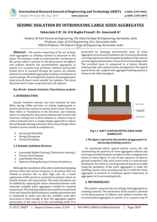
  • 1. International Research Journal of Engineering and Technology (IRJET) e-ISSN: 2395-0056 Volume: 04 Issue: 08 | Aug -2017 www.irjet.net p-ISSN: 2395-0072 © 2017, IRJET | Impact Factor value: 5.181 | ISO 9001:2008 Certified Journal | Page 1829 SEISMIC ISOLATION BY INTRODUCING LARGE SIZED AGGREGATES Suhas Jain C B1, Dr. B K Raghu Prasad2, Dr. Amarnath K3 1Student, M-Tech Structural Engineering, The Oxford College Of Engineering, Karnataka, India 2Professor, Dept. of Civil Engineering, IIS-c, Karnataka, India 3HOD & Professor, The Oxford College Of Engineering, Karnataka, India ----------------------------------------------------------***-------------------------------------------------------------- Abstract - The system comprising of the use of large sized aggregates as isolating material is discussed in this paper. The attempt is made to understand the mechanism of the system which is pivoted on the phenomenon of stiffness and collision between the accommodated aggregates in system. It is a passive way of Seismic Isolation and exerted seismic force is conveyed through the system via collision between accommodated aggregates leading in dissipation of seismic energy. The arrangementofsystemencouraginglesser value of work done is more suitable for Isolation. The above discussed work is done using Staad-pro v8i software Key Words: Seismic Isolation, Time history analysis 1. INTRODUCTION Seismic Isolation concept was first reported by John Milne during 1890s and later on widely implemented as seismic protection system in seismic prone areas. The term Base refers to Foundation of the Structure and Isolation refers to reducing the interaction between the Ground and structure resting over it. Base Isolation is a Passive way to reduce demand and it is simple design approach to reduce the earthquake damage potential. Three major thingsa Base Isolation system should accomplish are,  Horizontal Flexibility  Energy Dissipation  Vertical Flexibility 1.1 Seismic Isolation Devices  Laminated Rubber bearing ( Elastomeric bearing )  Viscous Fluid Damper  Lead Rubber Bearing  Spherical Sliding Bearing ( Friction Pendulum ) Althoughtheinstallationoftheabovementioneddamping devices reduce the seismic response in structures, they are limited in practice due to their high cost. As a result application of this system is restricted to projects where its benefit exceeds cost requirement. This major drawback can be fulfilled by replacing the above mentioned devices with naturally available stone aggregates crushed to required proportions. The Isolating system discussed here isassumed to be well suited forRaft foundation.Initiallypenetrationtest is conducted to make sure that the available earth after excavation is hard enough to bear the aggregates against penetration of the same in to the surrounding earth. It is proceeded by dumping preconceived mass of stone aggregates in excavated foundation pit. If scenario demands, covering may be provided along the periphery of the mass to prevent against penetration of mass in to surrounding earth. The provided mass is compacted to a known density. Subsequently raft is placed on the arrangement. The typical layout of the raft coupled with aggregate Isolating system is shown in the following figure. Fig 1.1 RAFT COUPLED WITH LARGE SIZED AGRREGATE ( The figure represents the position of aggregates in discussing Isolating system ) As mentioned above, typical section across the raft representing the position of stone aggregates without any covering provided along the peripheryofthearrangementis shown in above figure. In case of any existence of adverse ground condition ( silty sand, moist earth ) is noticed near foundation, Tar sheet as covering material may be provided along the periphery of the stone aggregates to make the Isolating system water proofing and also to held the stone aggregates in position to withstand against dispersion of aggregates in to surrounding Earth. 2. METHODOLOGY The system comprises the use of large sized aggregatesas isolating material. The mechanism of the system is pivoted on the phenomenon of stiffness and collision between the accommodated aggregates in system. It is a passive way of
  • 2. International Research Journal of Engineering and Technology (IRJET) e-ISSN: 2395-0056 Volume: 04 Issue: 08 | Aug -2017 www.irjet.net p-ISSN: 2395-0072 © 2017, IRJET | Impact Factor value: 5.181 | ISO 9001:2008 Certified Journal | Page 1830 Seismic Isolation, Seismic force is conveyed through the system via collision between accommodated aggregates. Fig 1.2 Typical section of system ( Figure represents the typical section of Isolating system where the stone aggregates are connected by links/springs ) During the process, the gained collision intensity by aggregates is directly proportional to dissipated seismic energy unless the boundary conditions are considered. The vital boundary conditions to be considered are,  Density of surrounding earth (naturally of Lithosphere)  Surface hardness and moisture content of bounding earth  Weight of Structure The layers of solid masses are modeled and the bottom most layer of solid masses are assigned fixed restraint. All solid masses are connected to each other by springs assigning the stiffness values varying from zero for very loose condition to infinity for very stiff/rigidcondition.Thus the bottom layer is made fixed to groundandthesubsequent upper layers are subjected to experience all 6 Degrees of Freedom and its magnitude will vary with respecttovarying stiffness of connecting springs and applied lateral force. The stiffness values assigned are according to the compaction of aggregates mass in actual practice. The analysis is done by assigning uniform stiffness for springs. With reference to compaction of whole mass of aggregate in actual, the exact stiffness between any two solid masses is unpredictableand thus the stiffness values of spring shall be randomly varied for analysis purpose. The behavior of system is analyzed for free vibration state and subsequently the structure is made to rest on the system and responses are compared with conventional structure. It is known that largely arranged particles when hit each other, they dissipates energy through heat. In fact loose and non-uniformly packed particles are much more effective. While packing certain sensitive electronic instruments,they are surrounded by loosely and randomly arranged thermocole particles filled with air,theidea beingthatunder impact to the bag containing the instrument, the thermocole particles collide each other smoothly as suspension is provided in the form of air filling in them, leading to less impact on instrument. This phenomenon is been carried here by replacing individual thermocole units by stone aggregates, air filling is replaced by soil mass and link elements, impact on bag is here considered as adverse seismic activity and finally instrument inside the bag is replaced by the structure. Fig 1.3 TYPICAL SECTION OF ISOLATING SYSTEM MODELED IN STAAD-PRO ( Arrangement of aggregates in typical section modeled in Staad-pro software is shown in the figure. Here the soil mass is provided as link element between stone aggregates ) As shown in the above figure the stone aggregates are packed by providing soil mass and air gap in between them. The modeling of isolating system is done in Staad pro V8i software. Initially the material propertiesofstoneaggregate, soil mass and link elements are defined. The provision is provided in Staad pro software to model solid elementsand thus each stone aggregate is modeled as solid element by assigning their respectiveproperty.Theconnectionbetween the stone aggregates is done in two ways i.e. by providing, a) line element at corners of solid stone mass assigning preconceived stiffness/Young’s Modulus value. b) Solid element of soil mass at all edges of stone aggregate. The study is carried out by considering theTimeHistory analysis data of El Centro Earthquake. The deformed shape of typical section under the application of seismic force is shown in the following figure, Fig 1.4 BEHAVIOUR OF AGGREGATES
  • 3. International Research Journal of Engineering and Technology (IRJET) e-ISSN: 2395-0056 Volume: 04 Issue: 08 | Aug -2017 www.irjet.net p-ISSN: 2395-0072 © 2017, IRJET | Impact Factor value: 5.181 | ISO 9001:2008 Certified Journal | Page 1831 The above mentioned typical section is made to experience the seismic activity and as expected earlier we noticed the deformed pattern of arrangement represents significantly the existence of collision between the stone aggregates. Analyzing the behavior of system, conclusion can be drawn that propagation of seismic wavesthroughthe arrangement occurs via collision between the accommodated aggregates and leading to dissipation of seismic energy. However impact being contact mechanics,is not modeled in the present work. The springs representing the resistance between the aggregates deform to absorb the energy. The problem is considered as linear, if non-linearity and hysteresis curve are considered, even the dissipated energy can be obtained. Thus the Raft is suspended from impact of adverse seismic waves. The soil mass provided between stones offers suspension for inter-particlecollision and in turn the whole arrangement ofIsolationsystemoffers suspension against direct impact of adverse seismic waves on structure. The System is assumed to be well suited for Raft footing. Initially penetration test is conducted to make sure that the available Earth after excavation is hard enough to bear the aggregates against penetration of the same in to earth. It is proceeded by dumping calculated mass of aggregates in excavated pit. If scenario demands , the covering may be provided along the periphery of the mass to persist against penetration of mass in to the surrounding earth. The provided mass is compacted to preconceived density. All sectional properties, physical properties must achieve preconceived data. SubsequentlyRaftismadetosettleabove the arrangement as shown in typical section. 3. MODELLING OF ISOLATING SYSTEM The heart of the Isolating system is being the nature of aggregates, each aggregate is modeled as solid element and assigned with respective properties of naturally available stone aggregate. Provision to model solid element and assigning required properties to same is been provided in Staad Pro software. The system is assemblage of a largenumberofaggregates. In order to analyze its behavior, initially modeling of single unit composed of 2 stone masses fastened by links and soil mass is done. Subsequently number of units areincreased to achieve required size. A typical model including two solid elements connected to each other by line elements provided as link at all four corners of solid is shown in the following Figure. Fig 1.5: MODEL OF TWO STONE MASS ( Single unit of the Isolating system is shown in figure which is composed of 2 stone masses connected to each other by line elements to act as link of desired stiffness ) As mentioned above, all modeling and analysis work is done in Staad Pro V8i software. Modelingofstoneaggregate of required size is done using Draw Solid command.Keeping the size of aggregate as reference eight nodes are created and is proceeded by drawing solid element using Add 8 Noded Solids command. Subsequently Line element of preconceived thickness & stiffness properties is drawn between the stone aggregates. Fig 1.6: STAAD PRO- 2 SOLID MODEL ( Typical modeling of two solid masses in Staad- Pro software is shown in above figure ) The project is carried out by considering 60mm size of stone aggregate and 20mm diameter of circularlineelement which is provided as link element as standard size. Stiffness of link elements is varied from 0.001 to 10^7 KN/m. All corners of adjacent solids are connected with link elements. The stiffness values assigned for beam elements & corresponding Young’s & Shear Modulus are as follows,
  • 4. International Research Journal of Engineering and Technology (IRJET) e-ISSN: 2395-0056 Volume: 04 Issue: 08 | Aug -2017 www.irjet.net p-ISSN: 2395-0072 © 2017, IRJET | Impact Factor value: 5.181 | ISO 9001:2008 Certified Journal | Page 1832 Table -1: Properties of Line elements STIFFNESS (K KN/m) YOUNG’s MODULUS (E KN/m^2) SHEAR MODULUS (G KN/m^2) 0.01 0.32 0.1455 0.1 3.2 1.4545 1.0 32 14.5455 100 3200 1454.5455 10000 3.2x10^5 145454.54 55 25x10^5 8x10^7 3.6x10^7 50x10^5 2x10^8 9x10^7 1x10^7 3.2x10^8 1.45x10^8 Similarly, a typical model including two stoneaggregates connected to each other by soil mass modeled as solid element is provided as link member at edges of solid is shown in the following Figure. Fig 1.7: Two stones plugged with soil mass ( Single unit representing the Soil mass as connecting element between two stones is shown in above figure ) As shown in above Figure, soil mass is sandwiched between stone aggregates. The highlighted part in figure represents soil mass. Young’s Modulus of soil mass is varied from 15000 KN/m^2 for loose soil mass to 30000 KN/m^2 for fully compacted soil mass & is directly proportional to stiffness between aggregates. The values of E and G of soil mass are, Table 1.2: Properties of Soil mass Young’s Modulus, E (KN/m2) Shear Modulus, G (KN/M2) Stiffness, K (KN/m) 15000 ( loose ) 5358 2700 20000 ( medium ) 7145 3600 25000 ( stiff ) 8929 4500 30000 ( fully compacted ) 10715 5400 The solid massesmodeledalongtheperipheryofthesystem are assigned with the properties of Earth crust. The material properties of Stone, Crust, Sand, Horizantle and Vertical line elements of a typical example model is shown in the Figure below. By keeping the materialpropertyofstoneandCrustas constant, the properties of sand and horizontal links are varied by assigning the properties listed out in Table 1.3 Table 1.3: Material Properties The properties of connecting elements listed out in Table 1.3 is kept as standard and number of models with different sizes, cross sections, loadings were created and link elements in each model is assigned with each material property. Thus the behavior of each different model is studied by assigning all stiffness properties mentioned in Tables 1.3 above. The gap between the stones aggregates in actual site varies, but for modeling purpose uniform gap of thickness 20mm filled with soil mass is considered. The different sizes of system are modeled for the analysis purpose and is varied from 0.0005 m3 to 4 m3. The following list of sizes of arrangement are considered for analysis purpose, 1. ( 0.06 x 0.18 x 0.08 ) m 2. ( 0.14 x 0.18 x 0.08 ) m 3. ( 0.14 x 0.18 x 0.16 ) m 4. ( 0.06 x 1.00 x 0.50 ) m 5. ( 0.06 x 1.62 x 0.82 ) m 6. ( 1.00 x 1.00 x 0.25 ) m 7. ( 1.00 x 1.00 x 0.50 ) m 8. ( 1.40 x 1.40 x 0.25 ) m 9. ( 1.40 x 1.40 x 0.50 ) m 10. ( 4.00 x 4.00 x 0.25 ) m
  • 5. International Research Journal of Engineering and Technology (IRJET) e-ISSN: 2395-0056 Volume: 04 Issue: 08 | Aug -2017 www.irjet.net p-ISSN: 2395-0072 © 2017, IRJET | Impact Factor value: 5.181 | ISO 9001:2008 Certified Journal | Page 1833 Fig 1.8 : Different sizes of system ( Figure shows the different sizes and arrangement of stone masses, soil masses and line elements ) All the modeled sections are analyzed by applying vertical load where the load denotes weight of structure in actual. The application of vertical load is carried out by placing Plate element of concrete material of suitable sections satisfying desired load quantity above the arrangement of aggregates. The Plate elementresembles the raft footing in actual which made it to use as loadingelement here & all models are assigned with constant seismic parameters of El Centro Earthquake. The typical section of loading on Isolating system and loads applied for analysis purpose corresponding to cross section of plate element are as follows, Fig 1.9: Loading on system ( Plate element as loading material is placed above the arrangement is shown here ) Table 1.4 (a) & (b) : Sizes of Plate element corresponding to loading PLATE DIMENSION ( L x B x D ) m LOAD in KN ( 0 x 0 x 0 ) 0 ( 0.94 x 0.94 x 0.05 ) 1.00 ( 0.94 x 0.94 x 0.1 ) 2.00 ( 0.94 x 0.94 x 0.2 ) 4.24 ( 0.94 x 0.94 x 0.4 ) 8.50 ( 0.94 x 0.94 x 1.6 ) 12.72 ( 0.94 x 0.94 x 0.8 ) 17.00 ( 0.94 x 0.94 x 1.0 ) 21.20 PLATE DIMENSION ( L x B x D ) m LOAD in KN ( 0 x 0 x 0 ) 0 ( 1.34 x 1.34 x 0.023 ) 1.00 ( 1.34 x 1.34 x 0.046 ) 2.00 ( 1.34 x 1.34 x 0.100 ) 4.30 ( 1.34 x 1.34 x 0.197 ) 8.50 ( 1.34 x 1.34 x 0.300 ) 13.00 ( 1.34 x 1.34 x 0.394 ) 17.00 ( 1.34 x 1.34 x 0.500 ) 21.55 The above mentioned loadings in Table (a) & (b) are done for sections ( 1.00 x 1.00 x 0.25 )m, ( 1.00 x 1.00 x 0.50 )m, ( 1.40 x 1.40 x 0.25 )m, ( 1.40 x 1.40 x 0.50 )m only. The analysis is carried out for different compaction values. Predominantly Compactionvalueisusedtofix/check the depth of system. The compaction value of system can be varied by two criteria, i.e. by keeping volume as constant, 1. Increasing stiffness/Young’s Modulus of connecting element The system is composed of large number of units containing 2 stone mass & an link each, values of stiffness & Young’s modulus of links is directlyproportional tocompactionvalue of system. The various values of stiffness & Young’smodulus is shown in Table (1) & (2) are assigned and analysis is carried out. 2. Increasing number of stone count by reducingthickness of soil element. Parallel way of varying compaction value of system is by keeping volume as constant thickness of link element is varied which in turn leads to number of stone count. Unit density of stone mass is same, variation in its count with constant system’s volume leads to variation in density of system. Density of any system is directly proportional to compaction value. The bottom most layer of Stone aggregates existing in contact with Ground below are assigned Fixed restraint and the layers above are connected by providing links. The typical arrangement is shown in following Figure,
  • 6. International Research Journal of Engineering and Technology (IRJET) e-ISSN: 2395-0056 Volume: 04 Issue: 08 | Aug -2017 www.irjet.net p-ISSN: 2395-0072 © 2017, IRJET | Impact Factor value: 5.181 | ISO 9001:2008 Certified Journal | Page 1834 Fig 1.10 : Support restraint ( All the joints which are in direct contact with below ground are assigned with fixed restraint ) The periphery stone aggregates along the direction of seismic wave are assigned with load of El Centroearthquake data. The earthquake load is assigned to highlighted solid masses of the arrangement shown in below Figure, Fig 1.11 : Application of Earthquake load ( The highlighted masses along the periphery are assigned with earthquake load ) For Time-History analysis purpose El Centro earthquake data is assigned for all models and comparison is done assuming the system is free from other external disturbances. The acceleration values of El Centro Earthquake for a time period up to 2.24 seconds are considered for analysis purpose. Fig 1.12 : Acceleration-Time History Plot ( Ground motion data recorded at a site in El Centro, California Imperial Valley earthquake of May 18, 1940 is shown in figure ) The number of modes are restricted to 10 in the study and the first mode shape of a typical arrangement is shown below. The analysis of all models with different size, cross sections, loadings, stiffness ofconnecting membersiscarried out by assigning the time period and corresponding acceleration data of El Centro earthquake. Initially the behavior of two stone aggregates linked with sand mass and surrounded by crust element is drawn and subsequently the number of all elements are increased and relative responses are drawn. The example models and their Natural Frequency, deflected shape along with size, corresponding Stiffness/Young’s Modulus of connecting element, Massparticipationfactors,Time-Accelerationcurve, Base reaction and Work done are listed below. The mentioned parameters are determined for all models categorized under different stiffness, sizes, varying imposed loads, but the most efficient models and their behavior are listed out below. The case in which the value of work done is less, that arrangement is highly encouraged for isolating system. Ex 1- Size = ( 0.06 x 0.18 x 0.08 ) m Young’s Modulus (E) = 30000 kN/m2 Load = Selfweight Fig 1.13 : Model & First Mode shape Model of two stone masses of60mmsizeeachishighlighted in figure connected to one other by soil mass of thickness being 20mm is shown in figure. The material property of soil mass assigned with very less stiffness value whose Young’s modulus being 15000 kN/m2. All the supports are assigned Fixed restraint. The analysis is done considering El-Centro earthquake data the very firstmode shape of arrangement is shown above. Table 1.5 : Frequency, Period & corresponding Mode numbers
  • 7. International Research Journal of Engineering and Technology (IRJET) e-ISSN: 2395-0056 Volume: 04 Issue: 08 | Aug -2017 www.irjet.net p-ISSN: 2395-0072 © 2017, IRJET | Impact Factor value: 5.181 | ISO 9001:2008 Certified Journal | Page 1835 The vales of frequencies, periods for corresponding modes are tabulated. The gradual decrease of time period and increase in frequency is observed in the analysis. Table 1.6 : Mass Participation Factors The massparticipationvaluesanditscumulativeweight of above model in all global directions is shown in above Table. The arrangement is experiencing maximum response/deformation in global X-direction. Fig 1.14 : Model & Time v/s Displacement spectra The spectra relating Time and acceleration values in all three i.e. X, Y and Z direction is shown in above figure. The arrangement is experiencing maximum acceleration at time 1.58 s. The acceleration is very much less in Z- direction. Table 1.7 : Base Reaction Under the action of ground motion on arrangement, the stone masses in the top layer experiencing maximum deformation is noticed. The base reaction and displacement experienced by the top most stone mass is highlighted in Table. Table 1.8 : Work done Work done = Base reaction x Lateral displacement The model experiencing less values of work done is more suitable and efficient arrangement. The work done values in directions X, Y , Z and equilibrium state are tabulated above. Ex 2- Size - ( 1.40 x 1.40 x 0.25 ) m Young’s Modulus (E) = 30000 kN/m2 Load = 21.55 kN Fig 1.15 : Model & First Mode shape Model of system of size being 0.50 m3 composed of stone masses of 60mm size each connected to one other by soil mass of thickness being 20mm is shown in figure. The material property of soil mass assigned with high stiffness value whose Young’s modulus being 30000 kN/m2. All the supports are assigned Fixed restraint. The loading on arrangement is done in the form of Plate element. The analysis is done considering El-Centro earthquake data and the very firstmode shape of arrangement is shown above.
  • 8. International Research Journal of Engineering and Technology (IRJET) e-ISSN: 2395-0056 Volume: 04 Issue: 08 | Aug -2017 www.irjet.net p-ISSN: 2395-0072 © 2017, IRJET | Impact Factor value: 5.181 | ISO 9001:2008 Certified Journal | Page 1836 Table 1.9 : Frequency, Period & corresponding Mode numbers The values of frequencies, periods for corresponding modes are tabulated. The gradual decrease of time period and increase in frequency is observed in the analysis. Table 1.10 : Mass Participation Factors The massparticipationvaluesanditscumulativeweight of above model in all global directions are shown in above Table. The arrangement is experiencing maximum response/deformation in global Z-direction. Fig 1.16 : Model & Time v/s Displacement spectra The spectra relating Time and acceleration values in X, Y and Z directions is shown in abovefigure.Thearrangementis experiencing maximum acceleration at time 1.58 s. Table 1.10 : Base Reaction Under the action of ground motion on arrangement, the stone masses in top layer experiencing maximum deformation is noticed. The base reaction and displacement experienced by the top most stone mass is highlighted in above Table. Table 1.11 : Work done Work done = Base reaction x Lateral displacement The model experiencing less values of work done is more suitable and efficient arrangement and the work donevalues in directions X, Y , Z and equilibrium state are tabulated above. The response of system composed of stone masses connected to one another through springs/line elements greatly depends on assigned stiffness values for link elements ranging from very loose/ zero stiffness to very large stiffness value when the aggregatesareinrigidcontact. However the arrangement in which the work done value is less, is more encouraged, here the arrangement of isolation system consisting soil mass of Young’s modulus 30000 kN/m2 is adopted for furtherwork whichincludes the comparison between conventional fixed base structure and structure plugged with isolation system. The typical twenty storied single bay framed structure is considered for the comparision purpose whose plan dimensions being (3x3) m and height of complete structure being 60 m. The size of Isolatingsystemis (4x4x0.5 )m, size of stone mass is 60mm and thickness of soil mass between stone aggregates is 20mm.
  • 9. International Research Journal of Engineering and Technology (IRJET) e-ISSN: 2395-0056 Volume: 04 Issue: 08 | Aug -2017 www.irjet.net p-ISSN: 2395-0072 © 2017, IRJET | Impact Factor value: 5.181 | ISO 9001:2008 Certified Journal | Page 1837 The analysis of framed model is done in two cases, case i. Framed model with Isolated footings with fixed restraints at base case ii. Framed model with Raft footing rested on Isolating system The analysis is done using Staad-Pro V8i software and the deformed shape of both structures relative to case i and case ii is shown in figure below, Fig 1.17 Deformed shape of Structure ( The deformed shape of structure with fixed restraint- left and base structure using large sized aggregates- right is shown in above figure ) Fig 1.18: Periods of Isolated and conventional structure The periods of isolated structure is found to be more compared to that of conventional one. The structure provided with fixed restraint at base is experienced a displacement of around 17 mm at top node of structure. Whereas we noticed very less or zero displacement in the same node of Isolated structure. The story drift plot for conventional and isolated structure is shown in following figure. Fig 1.19: Story drift plot for conventional structure Fig 1.20: Story drift plot for base isolated structure Fig 1.21: Comparison of conventional & Isolated structure
  • 10. International Research Journal of Engineering and Technology (IRJET) e-ISSN: 2395-0056 Volume: 04 Issue: 08 | Aug -2017 www.irjet.net p-ISSN: 2395-0072 © 2017, IRJET | Impact Factor value: 5.181 | ISO 9001:2008 Certified Journal | Page 1838 CONCLUSIONS:  The periods of isolated structure are marginally more compared to those of conventional one.  The technique presented in the paper involves filling up an excavated pit of certain known designed dimensions and just filling the pit with loose boulders/stones or in general coarse aggregates.  The technique can be called as passive isolation. It is easy to construct. The materials locally available can be employed and therefore does not involve much transportation and energy.Itcanthereforebe classified under sustainable technology.  The system in which the Young’s modulus of soil is assigned with 30000kN/m2 ( fully compacted soil mass ) is concluded as efficient one in this study.  The displacement at topmost nodeisverymuchless in Isolated structure compared to that of conventional one.  The work done in the case of an isolated structure is least which is also an encouraging feature.  Any structure built on such an isolated system shows much less displacement at the top compared to that of the conventional which proves that such passive isolation workswell evenwhensubjectedto an earthquake ground motion.  The drift of such a structure is almost nil which is very encouraging. ACKNOWLEDGEMENT It is with a feeling of great pleasure that I would like to express my most sincere heartfelt gratitude Sri. Dr. B K Raghu Prasad & Dr. Amarnath K for their valuable guidance. REFERENCES [1] Anand S.Arya, “Concepts & techniques for seismic base-isolation of structures” ISBN 9054100605 [2] Kubilay Kaptan, “Seismic Base Isolation & Energy absorbing devices”, European Scientific Journal [3] Gabriel Danila, “Seismic response control of buildings using Base Isolation”, IJMCS Vol 1 [4] Saiful Islam, “Seismic isolation in buildings to be practical reality”, JETR, Vol. 3(4) [5] Dynamics of Structures, Anil K Chopra, Etc…..